EP0310110A2 - Système de commutation de canaux sans parasite, du type (1+N) - Google Patents
Système de commutation de canaux sans parasite, du type (1+N) Download PDFInfo
- Publication number
- EP0310110A2 EP0310110A2 EP88116181A EP88116181A EP0310110A2 EP 0310110 A2 EP0310110 A2 EP 0310110A2 EP 88116181 A EP88116181 A EP 88116181A EP 88116181 A EP88116181 A EP 88116181A EP 0310110 A2 EP0310110 A2 EP 0310110A2
- Authority
- EP
- European Patent Office
- Prior art keywords
- channel
- switching
- error correction
- signal
- regular channels
- Prior art date
- Legal status (The legal status is an assumption and is not a legal conclusion. Google has not performed a legal analysis and makes no representation as to the accuracy of the status listed.)
- Granted
Links
Images


Classifications
-
- H—ELECTRICITY
- H04—ELECTRIC COMMUNICATION TECHNIQUE
- H04L—TRANSMISSION OF DIGITAL INFORMATION, e.g. TELEGRAPHIC COMMUNICATION
- H04L1/00—Arrangements for detecting or preventing errors in the information received
- H04L1/22—Arrangements for detecting or preventing errors in the information received using redundant apparatus to increase reliability
Definitions
- the present invention relates to a (1+N) hitless channel switching system, in a (1+N) digital transmission system having N regular channels and a single standby channel, for switching one of the regular channels to the standby channel with non-interruption.
- Fig. 1 is a block diagram showing a basic arrangement of a non-interruption regular/standby channel switching system generally used in radio digital transmission.
- a transmitting side 100 is connected to a receiving side 200 through n regular channels represented by CH1 to CH n and a single standby channel represented by CH P .
- the transmitting side 100 comprises: switches 11 having the same arrangement and provided to the regular channels CH1 to CH n to receive transmission signals IN1 to IN n ; multiplexers 12 having the same arrangement and provided to the regular channels CH1 to CH n and the standby channel CH P ; a pilot signal generator 16 for outputting a pilot signal; and a channel switching controller 18 for supplying a signal D to the switches 11 to control their switching operation.
- the pilot signal is output from the pilot signal generator 16 to the channel CH P through a line 202.
- the switch 11 connected to the channel CH1 is switched in accordance with the control signal D supplied from the channel switching controller 18, and a transmission signal of the channel CH1 is supplied through the standby channel CH P .
- the receiving side 200 comprises: channel monitors 13 for monitoring channel conditions of the standby channel CH P and the regular channels CH1 to CH n and outputting a standby channel condition signal B and regular channel condition signals A; demultiplexers 14 for demultiplexing the output signals from the channel monitors 13; switches 15 each for receiving the output signal from the demultiplexer 14 of the standby channel CH P at its one input terminal, receiving the output signal from a corresponding one of the demultiplexers 14 of the regular channels CH1 to CH n at its other input terminal, and selecting one of the input signals in accordance with a control signal E; a pilot signal detector 17 for detecting a pilot signal from the output signal from the demultiplexer 14 of the standby channel CH P ; and a channel switching controller 19 for outputting a switch control signal E for controlling the switches 15 in accordance with the standby channel condition signal B from the channel monitor 13 of the standby channel CH P , the regular channel condition signals A output from the channel monitors of the regular channels CH1 to CH n , and the output signal
- a switching sequence of hitless switching in Fig. 1 is generally performed as follows. That is, if a fault occurs on, e.g., the regular channel CH1, the channel monitor 13 of the channel CH1 supplies the signal A representing the fault to the channel switching controller 19.
- the channel switching controller 19 checks the presence/absence of the fault and the condition of the standby channel by using the standby channel condition signal B and the output signal C from the pilot signal detector 17 and then sends the switching demand signal to the channel switching controller 18 at the transmitting side 100.
- the channel switching controller 18 operates the switch 11 of the channel CH1 by the channel switching signal D.
- the channel switching controller 19 at the receiving side 200 compares the transmission signal from the regular channel CH1 on which the fault occurs with the transmission signal from the standby channel. If it is determined that bits and phases of the two signals coincide with each other, the switching (hitless switching) signal E is supplied to the switch 15.
- the switch 15 switches its input from the demultiplexer 14 of the channel CH1 to the demultiplexer 14 of the standby channel CH P and outputs it as an output signal OUT1. As a result, switching from the channel CH1 on which the fault occurs is completed.
- Fig. 2 is a block diagram showing a partial detailed arrangement of the system shown in Fig. 1 for monitoring channel quality by the parity check method which is conventionally often used.
- a transmission signal output from the multiplexer 12 is supplied to an error correction calculator 1 and to a parity counter 4.
- a count obtained by the parity counter 4 is supplied to the multiplexer 12 and inserted in a predetermined time slot.
- a signal subjected to error correction by an error correction circuit 2 is output to a demultiplexer 14 and a parity counter 5.
- the parity counter 5 performs parity counting similar to that of the parity counter 4 at the transmitting side 100 and outputs the count to a parity comparator 6.
- the demultiplexer 14 separates the parity inserted in the time slot by the multiplexer 12 at the transmitting side 100 and outputs the parity to the parity comparator 6.
- the parity comparator 6 compares the inputs from the parity counter 5 and the demultiplexer 14 and outputs a parity error signal based on the comparison result.
- a channel quality determination circuit 7 performs quality determination of the channel in accordance with the parity error signal and outputs the determination information to the channel switching controller 19.
- an object of the present invention to eliminate the above drawback of the conventional technique and provide an apparatus capable of rapidly and reliably detecting a fault of a propagation path and restoring the propagation path by hitless switching in switching of a radio digital transmission system having an error correction function.
- a (1+N) hitless channel switching system (N 1) of a digital transmission system having an error correction function comprises a detecting means, provided at a receiving side, for detecting a bit error rate before error correction, and a means for performing channel switching with non-interruption in accordance with the detected bit error rate.
- Fig. 3 shows an arrangement of a main part of the embodiment of the present invention.
- an output signal from a multiplexer 12 is supplied to an error correction calculator 1, and the error correction calculator 1 performs calculation in accordance with an error correction system.
- the calculation result is transmitted to a receiving side 200 using a time slot (redundant bit) through a corresponding channel CH j .
- an error correction circuit 2 corrects a bit error in a bit sequence before error correction using the error correction calculation result according to the error correction system and the contents of the redundant bit and outputs a signal subjected to error correction to a demultiplexer 14 and a signal G representing this bit error rate.
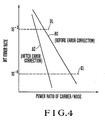
- the signal G representing the bit error rate is generated on the basis of channel quality of the bit sequence before error correction. Therefore, as shown by a line BC in Fig. 4, a time interval from channel quality degradation information detection (e.g., an error rate 10 ⁇ 6 point) to system outage (e.g., an error rate 10 ⁇ 3 point) is sufficient as compared with that in channel quality determination based on a bit sequence after error correction.
- channel quality degradation information detection e.g., an error rate 10 ⁇ 6 point
- system outage e.g., an error rate 10 ⁇ 3 point
- a channel quality determination circuit 3 performs channel quality determination of the bit sequence before error correction by using the error correction control signal G and outputs a signal A representing channel quality degradation.
- a switching apparatus can sufficiently follow a quality degradation speed of a propagation path because channel quality monitoring is performed before error correction.
Landscapes
- Engineering & Computer Science (AREA)
- Computer Networks & Wireless Communication (AREA)
- Signal Processing (AREA)
- Detection And Prevention Of Errors In Transmission (AREA)
- Time-Division Multiplex Systems (AREA)
Applications Claiming Priority (2)
| Application Number | Priority Date | Filing Date | Title |
|---|---|---|---|
| JP248082/87 | 1987-10-02 | ||
| JP62248082A JPH084257B2 (ja) | 1987-10-02 | 1987-10-02 | (1+n)ヒットレス回線切替装置 |
Publications (3)
| Publication Number | Publication Date |
|---|---|
| EP0310110A2 true EP0310110A2 (fr) | 1989-04-05 |
| EP0310110A3 EP0310110A3 (en) | 1990-01-31 |
| EP0310110B1 EP0310110B1 (fr) | 1994-04-06 |
Family
ID=17172941
Family Applications (1)
| Application Number | Title | Priority Date | Filing Date |
|---|---|---|---|
| EP88116181A Revoked EP0310110B1 (fr) | 1987-10-02 | 1988-09-30 | Système de commutation de canaux sans parasite, du type (1+N) |
Country Status (5)
| Country | Link |
|---|---|
| US (1) | US4961190A (fr) |
| EP (1) | EP0310110B1 (fr) |
| JP (1) | JPH084257B2 (fr) |
| AU (1) | AU613093B2 (fr) |
| DE (1) | DE3888909T2 (fr) |
Cited By (8)
| Publication number | Priority date | Publication date | Assignee | Title |
|---|---|---|---|---|
| FR2653957A1 (fr) * | 1989-10-27 | 1991-05-03 | Alcatel Transmission | Procede et dispositif d'etablissement des demandes de commutation dans une installation de transmission numerique de type "n+1" dans laquelle au moins un canal principal est equipe d'un dispositif de correction d'erreurs. |
| EP0417739A3 (en) * | 1989-09-11 | 1992-07-29 | Fujitsu Limited | Speech coding apparatus using multimode coding |
| EP0492438A3 (en) * | 1990-12-20 | 1993-06-09 | Fujitsu Limited | Method and system for making bipolar switching to protection channel |
| GB2267415A (en) * | 1992-05-19 | 1993-12-01 | Sony Broadcast & Communication | Signal switching |
| DE4328523A1 (de) * | 1993-08-25 | 1995-03-02 | Telefunken Microelectron | Vorrichtung zur Datenübertragung auf elektrischen Niederspannungsnetzen |
| WO1995033322A1 (fr) * | 1994-05-27 | 1995-12-07 | British Telecommunications Public Limited Company | Systeme de transmission de donnees dote d'un dispositif de commutation de canaux |
| WO2003073423A1 (fr) * | 2002-02-26 | 2003-09-04 | Storage Technology Corporation | Systeme et procede pour corriger des erreurs de decodage multi-canal |
| US7055081B2 (en) | 2001-03-02 | 2006-05-30 | Storage Technology Corporation | System and method for multi-channel decoding error correction |
Families Citing this family (18)
| Publication number | Priority date | Publication date | Assignee | Title |
|---|---|---|---|---|
| GB8813958D0 (en) * | 1988-06-13 | 1988-07-20 | Plessey Telecomm | Data path protection |
| JPH02149040A (ja) * | 1988-11-30 | 1990-06-07 | Toshiba Corp | データ伝送方式 |
| JPH0456441A (ja) * | 1990-06-25 | 1992-02-24 | Mitsubishi Electric Corp | リング型ローカルエリアネットワーク |
| FR2670971A1 (fr) * | 1990-12-21 | 1992-06-26 | Trt Telecom Radio Electr | Systeme de transmission de mots de donnees utilisant au moins deux canaux de transmission. |
| US5485465A (en) * | 1992-05-20 | 1996-01-16 | The Whitaker Corporation | Redundancy control for a broadcast data transmission system |
| JPH06224852A (ja) * | 1993-01-25 | 1994-08-12 | Matsushita Electric Ind Co Ltd | 光伝送方式 |
| JP3179957B2 (ja) * | 1994-02-28 | 2001-06-25 | 富士通株式会社 | マルチメディア通信における受信装置及び受信信号出力方法 |
| US5742646A (en) * | 1995-05-05 | 1998-04-21 | Harris Corporation | Method of selecting and switching signal paths in a digital communication system |
| JP4300720B2 (ja) * | 2001-06-29 | 2009-07-22 | Kddi株式会社 | 光伝送システム及び回線切り替え方法 |
| JP4506452B2 (ja) * | 2004-12-22 | 2010-07-21 | 日本電気株式会社 | 回線切替装置および回線切替方法 |
| JP4637769B2 (ja) * | 2006-02-27 | 2011-02-23 | 京セラ株式会社 | 通信装置 |
| US7458139B2 (en) | 2006-09-22 | 2008-12-02 | Kyokutoh Co., Ltd | Tip dresser |
| US8095088B2 (en) | 2007-05-17 | 2012-01-10 | Harris Stratex Networks Operating Corporation | Compact wide dynamic range transmitter for point to point radio |
| US8395256B2 (en) * | 2007-02-02 | 2013-03-12 | Harris Stratex Networks Operating Corporation | Packaging for low-cost, high-performance microwave and millimeter wave modules |
| US7782765B2 (en) | 2007-01-22 | 2010-08-24 | Harris Stratex Networks Operating Corporation | Distributed protection switching architecture for point-to-point microwave radio systems |
| US8275071B2 (en) | 2007-05-17 | 2012-09-25 | Harris Stratex Networks Operating Corporation | Compact dual receiver architecture for point to point radio |
| JP2010183196A (ja) * | 2009-02-03 | 2010-08-19 | Fujitsu Ltd | データ転送システム、データ送信装置、データ受信装置及びデータ転送方法 |
| JP2014027332A (ja) * | 2012-07-24 | 2014-02-06 | Fujitsu Ltd | 伝送装置 |
Family Cites Families (13)
| Publication number | Priority date | Publication date | Assignee | Title |
|---|---|---|---|---|
| BE731482A (fr) * | 1968-05-15 | 1969-09-15 | ||
| US4234956A (en) * | 1978-10-11 | 1980-11-18 | The General Electric Company Limited | Digital relay systems |
| FR2473819B1 (fr) * | 1980-01-11 | 1985-12-13 | Telecommunications Sa | Procede et systeme de securisation d'une artere de transmission numerique |
| JPS6077546A (ja) * | 1983-10-05 | 1985-05-02 | Fujitsu Ltd | ディジタル無線回線の監視方式 |
| US4744083A (en) * | 1984-09-14 | 1988-05-10 | Geostar Corporation | Satellite-based position determining and message transfer system with monitoring of link quality |
| JPS61111037A (ja) * | 1984-11-05 | 1986-05-29 | Nec Corp | 回線切替方式 |
| JPS61111036A (ja) * | 1984-11-05 | 1986-05-29 | Nec Corp | 同期切替方式 |
| FR2574237B1 (fr) * | 1984-11-30 | 1992-05-22 | Telecommunications Sa | Systeme de commutation pour reseau de transmission numerique |
| JPS61283241A (ja) * | 1985-06-10 | 1986-12-13 | Nec Corp | デ−タ通信受信装置 |
| CA1249633A (fr) * | 1985-12-11 | 1989-01-31 | Hideaki Morimoto | Dispositif de commutation de canaux |
| DE3788532T2 (de) * | 1986-03-31 | 1994-04-21 | Nippon Electric Co | Funkübertragungssystem mit vereinfachter Fehlerkorrekturschaltung und schneller Kanalumschaltung. |
| JPS6333028A (ja) * | 1986-07-26 | 1988-02-12 | Nec Corp | 信号検出方式 |
| JPS6377235A (ja) * | 1986-09-20 | 1988-04-07 | Fujitsu Ltd | デイジタル通信システムの切替方式 |
-
1987
- 1987-10-02 JP JP62248082A patent/JPH084257B2/ja not_active Expired - Lifetime
-
1988
- 1988-09-30 DE DE3888909T patent/DE3888909T2/de not_active Revoked
- 1988-09-30 EP EP88116181A patent/EP0310110B1/fr not_active Revoked
- 1988-10-03 US US07/251,643 patent/US4961190A/en not_active Expired - Lifetime
- 1988-10-04 AU AU23389/88A patent/AU613093B2/en not_active Expired
Cited By (12)
| Publication number | Priority date | Publication date | Assignee | Title |
|---|---|---|---|---|
| EP0417739A3 (en) * | 1989-09-11 | 1992-07-29 | Fujitsu Limited | Speech coding apparatus using multimode coding |
| US5224167A (en) * | 1989-09-11 | 1993-06-29 | Fujitsu Limited | Speech coding apparatus using multimode coding |
| FR2653957A1 (fr) * | 1989-10-27 | 1991-05-03 | Alcatel Transmission | Procede et dispositif d'etablissement des demandes de commutation dans une installation de transmission numerique de type "n+1" dans laquelle au moins un canal principal est equipe d'un dispositif de correction d'erreurs. |
| EP0492438A3 (en) * | 1990-12-20 | 1993-06-09 | Fujitsu Limited | Method and system for making bipolar switching to protection channel |
| US5311170A (en) * | 1990-12-20 | 1994-05-10 | Fujitsu Limited | Method and system for making bipolar switching to protection channel |
| GB2267415A (en) * | 1992-05-19 | 1993-12-01 | Sony Broadcast & Communication | Signal switching |
| GB2267415B (en) * | 1992-05-19 | 1996-02-07 | Sony Broadcast & Communication | Signal switching |
| DE4328523A1 (de) * | 1993-08-25 | 1995-03-02 | Telefunken Microelectron | Vorrichtung zur Datenübertragung auf elektrischen Niederspannungsnetzen |
| WO1995033322A1 (fr) * | 1994-05-27 | 1995-12-07 | British Telecommunications Public Limited Company | Systeme de transmission de donnees dote d'un dispositif de commutation de canaux |
| US5680389A (en) * | 1994-05-27 | 1997-10-21 | British Telecommunications Public Limited Company | Data transmission system |
| US7055081B2 (en) | 2001-03-02 | 2006-05-30 | Storage Technology Corporation | System and method for multi-channel decoding error correction |
| WO2003073423A1 (fr) * | 2002-02-26 | 2003-09-04 | Storage Technology Corporation | Systeme et procede pour corriger des erreurs de decodage multi-canal |
Also Published As
| Publication number | Publication date |
|---|---|
| US4961190A (en) | 1990-10-02 |
| EP0310110B1 (fr) | 1994-04-06 |
| AU2338988A (en) | 1989-04-06 |
| EP0310110A3 (en) | 1990-01-31 |
| JPH0191544A (ja) | 1989-04-11 |
| DE3888909D1 (de) | 1994-05-11 |
| AU613093B2 (en) | 1991-07-25 |
| JPH084257B2 (ja) | 1996-01-17 |
| DE3888909T2 (de) | 1994-07-21 |
Similar Documents
| Publication | Publication Date | Title |
|---|---|---|
| US4961190A (en) | (1+N) Hitless channel switching system | |
| US5577196A (en) | Intelligent digital signal hitless protection switch | |
| US20030037297A1 (en) | Frame synchronization device and frame synchronization method | |
| US5555248A (en) | Tandem connection maintenance system | |
| US6920603B2 (en) | Path error monitoring method and apparatus thereof | |
| EP0225643B1 (fr) | Système de commutation de canal | |
| US5515362A (en) | Digital signal transmission apparatus | |
| KR20000052456A (ko) | 리드솔로몬 복호 장치와 그 제어 방법 | |
| US6870859B1 (en) | Multiplexing system and multiplexing method of tributary signals | |
| EP0740435B1 (fr) | Alignement de bits de parité pour éliminer les erreurs lors de la commutation d'un circuit de traitement actif à un circuit en état de veille | |
| EP1210786B1 (fr) | Commutation de signal | |
| JPH09219720A (ja) | 通信ネットワークにおける障害検出方法及び装置 | |
| JP2616695B2 (ja) | 回線切替装置 | |
| US20040190463A1 (en) | Change-over apparatus | |
| JPS6216589B2 (fr) | ||
| JP4506452B2 (ja) | 回線切替装置および回線切替方法 | |
| JPH02285830A (ja) | 同期切替装置 | |
| JPH10154972A (ja) | 無瞬断切替方式 | |
| US20050111373A1 (en) | Node device | |
| JPH05291982A (ja) | 回線切替方式 | |
| JP2010093517A (ja) | 回線品質検出装置、回線品質検出方法及びそれを用いた回線切替装置、回線切替方法 | |
| JP2002290421A (ja) | データ伝送異常監視方法及びシステム | |
| JPH01273445A (ja) | 多重伝送方式 | |
| JPH01149634A (ja) | 回線切替装置 | |
| JPH04364620A (ja) | 監視方式 |
Legal Events
| Date | Code | Title | Description |
|---|---|---|---|
| PUAI | Public reference made under article 153(3) epc to a published international application that has entered the european phase |
Free format text: ORIGINAL CODE: 0009012 |
|
| 17P | Request for examination filed |
Effective date: 19880930 |
|
| AK | Designated contracting states |
Kind code of ref document: A2 Designated state(s): DE GB SE |
|
| PUAL | Search report despatched |
Free format text: ORIGINAL CODE: 0009013 |
|
| AK | Designated contracting states |
Kind code of ref document: A3 Designated state(s): DE GB SE |
|
| 17Q | First examination report despatched |
Effective date: 19920221 |
|
| GRAA | (expected) grant |
Free format text: ORIGINAL CODE: 0009210 |
|
| AK | Designated contracting states |
Kind code of ref document: B1 Designated state(s): DE GB SE |
|
| REF | Corresponds to: |
Ref document number: 3888909 Country of ref document: DE Date of ref document: 19940511 |
|
| PLBI | Opposition filed |
Free format text: ORIGINAL CODE: 0009260 |
|
| EAL | Se: european patent in force in sweden |
Ref document number: 88116181.4 |
|
| 26 | Opposition filed |
Opponent name: SIEMENS AG Effective date: 19950105 |
|
| PLBQ | Unpublished change to opponent data |
Free format text: ORIGINAL CODE: EPIDOS OPPO |
|
| PLAB | Opposition data, opponent's data or that of the opponent's representative modified |
Free format text: ORIGINAL CODE: 0009299OPPO |
|
| R26 | Opposition filed (corrected) |
Opponent name: SIEMENS AG Effective date: 19950105 |
|
| RDAH | Patent revoked |
Free format text: ORIGINAL CODE: EPIDOS REVO |
|
| APAC | Appeal dossier modified |
Free format text: ORIGINAL CODE: EPIDOS NOAPO |
|
| APAE | Appeal reference modified |
Free format text: ORIGINAL CODE: EPIDOS REFNO |
|
| APAC | Appeal dossier modified |
Free format text: ORIGINAL CODE: EPIDOS NOAPO |
|
| PGFP | Annual fee paid to national office [announced via postgrant information from national office to epo] |
Ref country code: SE Payment date: 20010918 Year of fee payment: 14 |
|
| PGFP | Annual fee paid to national office [announced via postgrant information from national office to epo] |
Ref country code: GB Payment date: 20011003 Year of fee payment: 14 |
|
| APAC | Appeal dossier modified |
Free format text: ORIGINAL CODE: EPIDOS NOAPO |
|
| PGFP | Annual fee paid to national office [announced via postgrant information from national office to epo] |
Ref country code: DE Payment date: 20011015 Year of fee payment: 14 |
|
| RDAG | Patent revoked |
Free format text: ORIGINAL CODE: 0009271 |
|
| STAA | Information on the status of an ep patent application or granted ep patent |
Free format text: STATUS: PATENT REVOKED |
|
| 27W | Patent revoked |
Effective date: 20011012 |
|
| GBPR | Gb: patent revoked under art. 102 of the ep convention designating the uk as contracting state |
Free format text: 20011012 |
|
| APAH | Appeal reference modified |
Free format text: ORIGINAL CODE: EPIDOSCREFNO |