EP0310391A2 - Axiallüfter - Google Patents
Axiallüfter Download PDFInfo
- Publication number
- EP0310391A2 EP0310391A2 EP88309047A EP88309047A EP0310391A2 EP 0310391 A2 EP0310391 A2 EP 0310391A2 EP 88309047 A EP88309047 A EP 88309047A EP 88309047 A EP88309047 A EP 88309047A EP 0310391 A2 EP0310391 A2 EP 0310391A2
- Authority
- EP
- European Patent Office
- Prior art keywords
- yoke
- fan
- housing
- hub
- axial flow
- Prior art date
- Legal status (The legal status is an assumption and is not a legal conclusion. Google has not performed a legal analysis and makes no representation as to the accuracy of the status listed.)
- Granted
Links
- WABPQHHGFIMREM-UHFFFAOYSA-N lead(0) Chemical compound [Pb] WABPQHHGFIMREM-UHFFFAOYSA-N 0.000 description 8
- 238000004519 manufacturing process Methods 0.000 description 4
- 238000003780 insertion Methods 0.000 description 3
- 230000037431 insertion Effects 0.000 description 3
- 239000002184 metal Substances 0.000 description 3
- 230000002093 peripheral effect Effects 0.000 description 3
- 238000003825 pressing Methods 0.000 description 3
- 230000008439 repair process Effects 0.000 description 3
- 239000000853 adhesive Substances 0.000 description 2
- 230000001070 adhesive effect Effects 0.000 description 2
- 238000004049 embossing Methods 0.000 description 2
- 238000000465 moulding Methods 0.000 description 2
- 238000004080 punching Methods 0.000 description 2
- 238000003466 welding Methods 0.000 description 2
- 230000008878 coupling Effects 0.000 description 1
- 238000010168 coupling process Methods 0.000 description 1
- 238000005859 coupling reaction Methods 0.000 description 1
- 238000005520 cutting process Methods 0.000 description 1
- 230000007547 defect Effects 0.000 description 1
- 238000006073 displacement reaction Methods 0.000 description 1
- 239000000463 material Substances 0.000 description 1
- 238000000034 method Methods 0.000 description 1
- 239000002991 molded plastic Substances 0.000 description 1
- 239000004033 plastic Substances 0.000 description 1
- 229920003023 plastic Polymers 0.000 description 1
- 230000008569 process Effects 0.000 description 1
- 238000007493 shaping process Methods 0.000 description 1
Images


Classifications
-
- F—MECHANICAL ENGINEERING; LIGHTING; HEATING; WEAPONS; BLASTING
- F04—POSITIVE - DISPLACEMENT MACHINES FOR LIQUIDS; PUMPS FOR LIQUIDS OR ELASTIC FLUIDS
- F04D—NON-POSITIVE-DISPLACEMENT PUMPS
- F04D25/00—Pumping installations or systems
- F04D25/02—Units comprising pumps and their driving means
- F04D25/06—Units comprising pumps and their driving means the pump being electrically driven
- F04D25/0606—Units comprising pumps and their driving means the pump being electrically driven the electric motor being specially adapted for integration in the pump
- F04D25/0613—Units comprising pumps and their driving means the pump being electrically driven the electric motor being specially adapted for integration in the pump the electric motor being of the inside-out type, i.e. the rotor is arranged radially outside a central stator
- F04D25/0633—Details of the magnetic circuit
-
- F—MECHANICAL ENGINEERING; LIGHTING; HEATING; WEAPONS; BLASTING
- F04—POSITIVE - DISPLACEMENT MACHINES FOR LIQUIDS; PUMPS FOR LIQUIDS OR ELASTIC FLUIDS
- F04D—NON-POSITIVE-DISPLACEMENT PUMPS
- F04D29/00—Details, component parts, or accessories
- F04D29/60—Mounting; Assembling; Disassembling
- F04D29/64—Mounting; Assembling; Disassembling of axial pumps
- F04D29/644—Mounting; Assembling; Disassembling of axial pumps especially adapted for elastic fluid pumps
- F04D29/646—Mounting or removal of fans
Definitions
- the present invention relates to an axial flow fan and, although it is not so restricted, it relates more particularly to an axial flow fan disposed in a casing of an office-automation instrument to circulate air therethrough so as to cool heated parts thereof.
- An axial flow fan comprising a rotary member provided with a fan member; a motor portion of an electric motor for rotating the rotary member; a circuit board carrying an electrical component or components for controlling the operation of the motor portion; and a housing having a housing portion to one side of which the rotary member and the motor portion are mounted.
- the motor portion and the circuit board are inserted into the housing from the same direction when they are assembled into a superposed structure.
- the central portion of the circuit board has a relatively large opening for the passage therethrough of a shaft support sleeve.
- the circuit board has a limited amount of space available for electrical components and there is limited flexibility for the arrangement of these components.
- the circuit board is disposed under and is covered by the motor portion so that it cannot be removed separately once it is assembled into the housing. Replacement, repair and adjustment of the circuit board are therefore difficult.
- an axial flow fan comprising a rotary member provided with a fan member; a motor portion of an electric motor for rotating the rotary member; a circuit board carrying an electrical component or components for controlling the operation of the motor portion; and a housing having a housing portion to one side of which the rotary member and the motor portion are mounted characterised in that the circuit board is mounted on the opposite side of the housing portion, the axial flow fan having been assembled by introducing the rotary member and the motor portion into the housing from the said one side, and introducing the circuit board into the housing from the said opposite side.
- the rotary member comprises a hollow fan hub having an opening at one end thereof, and a hollow yoke disposed inside the hub, the hollow yoke having a tapered shape such that its internal diameter increases towards the said hub opening.
- the yoke may be insert-moulded into the fan hub.
- the inner diameter of the said opening of the fan hub is greater than that of the end of the yoke remote from said opening.
- an axial flow fan comprising a rotary member provided with a fan member, a hollow fan hub having an opening at one end thereof, and a hollow yoke disposed within the hub; and a motor portion for rotating the rotary member characterised in that the hollow yoke has a tapered shape such that its internal diameter increases towards the hub opening.
- the yoke may be cup-shaped having an end portion with an opening therein in which a portion of the hub is mounted.
- the yoke and hub may be moulded together to form an integral structure.
- the yoke is preferably provided at its larger end portion with a radiused surface to facilitate the introduction into the yoke of a magnet which forms part of the rotary member.
- a known axial flow fan has a fan member 1, a fan shaft 4, a coil 8, a core 9, a Hall device 13, and a circuit board 10 to which the coil 8 is connected by a lead wire 15 and which is connected to a power source (not shown) by a power line 22.
- the circuit board 10 is secured to a housing 12 by a screw 24.
- the parts 8, 9 which form a motor portion and the circuit board 10 are inserted into the housing 12 from the same direction when they are assembled into a superposed structure.
- the fan shown in Figure 1 moreover, has a rotary member which, in addition to comprising the fan member 1 and shaft 4, also comrpises a hollow fan hub 25 having an opening at its bottom end and a hollow yoke 2 disposed inside the hub 25, a magnet 3 being mounted in and carried by the yoke 2.
- the yoke 2 and the hub 25 can be attached to each other by adhesive or by welding.
- the central portion of the circuit board 10 has a relatively large opening for the passage therethrough of a sleeve 5 which is used to support the shaft 4 by way of a ball bearing 6. Because of this, the circuit board 10 has a limited amount of effective space for electrical components and there is limited flexibility for the arrangement of these components. Further, the circuit board 10 is disposed under and is covered by the motor portion 8, 9 so that the circuit board 10 cannot be removed separately once it is assembled into the housing 12. Replacement, repair and adjustment of the circuit board 10 are therefore difficult.
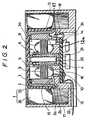
- FIG 2 there is therefore shown an axial flow fan according to the present invention in which a fan member 1 is insert-moulded together with a yoke 2, a magnet 3 and a shaft 4 to form an integrated rotary member.
- a sleeve 5 forms a shaft support portion of a housing 12 having a substantially U-shaped base portion 12 a .
- Inside the sleeve 5 there is mounted a ball bearing 6 and a ring 7 composed of oil-less metal.
- the sleeve 5 supports about it a motor or drive portion of an electric motor for rotating the said rotary member, the motor portion comprising a coil 8 and a core 9 which holds the coil 8.
- the fan member 1 is mounted on the shaft 4 which is itself rotatably mounted in the sleeve or shaft support portion 5.
- the shaft 4 is positioned in the thrust direction by means of a stopper washer 21 which is engaged in a slit recess formed in the end of the shaft 4.
- a circuit board 10 is attached to and disposed below the base portion 12 a of the housing 12 by means of a sole screw 24.
- the circuit board 10 has mounted thereon an electronic component 20 for controlling the operation of the motor portion 8, 9.
- a Hall device 13 is supported by and above the circuit board 10 by way of a support member 27 which is secured to the bottom of the circuit board 10.
- the Hall device 13 is mounted in position by passing it through a rectangular hole 14 in the base portion 12 a of the housing 12 so as to extend adjacent to a bottom face of the core 9 which will thus be adjacent the top of the Hall device 13.
- a lead wire 15 of the coil 8 passes downwardly through a round hole 16 in the base portion 12 a of the housing 12 and is attached to the circuit board 10.
- a cavity 17 in the bottom surface of the base portion 12 a of the housing 12 is provided to receive therein a curved intermediate portion of the lead wire 15 so as to avoid the application of excessive stress to the circuit board 10.
- a portion 18 of the base portion 12 a of the housing 12 is tapered to avoid vertical displacement of the circuit board 10 at the radially opposite side thereof from the housing 12 when the circuit board 10 is fixed to the housing 12 by means of the sole screw 24. Consequently, the motor portion 8, 9 and the rotary member 1-4, on the one hand, and the circuit board 10, on the other hand, are separately assembled into the housing 12 from opposite directions.
- the lead wire 15 from the assembled motor portion 8, 9 passes through the round hole 16 and is fitted into a peripheral recess 19 ( Figure 4) of the circuit board 10, being guided to the face of circuit board 10 and being connected thereat by welding.
- a power line 22 which supplies electric power from the outside, is connected to the circuit board 10.
- the circuit board 10 functions at least to interconnect the lead wire 15 and the power line 22 to each other.
- the yoke 2 is a hollow cup-shaped member formed by emboss-pressing and thereafter punch-pressing in the same direction while leaving top and bottom edge portions.
- the thus formed yoke 2 is insert-moulded to form an integrated hollow hub 25 in which the bottom edge portion 2 a of the yoke 2 surrounds the opening of the hollow hub 25.
- the opening edge 2 b of the hub 25 is made of moulded plastics and is disposed radially outside the bottom edge portion 2 a of the yoke 2.
- the inner diameter of the hub 25 at the opening edge 2 b is greater than that of the end of the yoke 2 remote from the opening edge 2 b .
- the shaft 4 is also insert-moulded as a part of the integrated fan member 1.
- the magnet 3 is formed with a step portion 3 a for positioning it.
- the magnet 3 is inserted through the bottom opening defined by the bottom edge portion 2 a of the yoke 2 and is fixed to the yoke 2 by adhesive.
- the thus formed yoke 2, magnet 3 and fan member 1 may be integrally moulded to form the rotary member.
- the top end portion of an embossed or press-drawn cup-shaped metal member is punch-pressed in the direction of an arrow B parallel to that of the emboss-pressing while leaving a peripheral portion of the top end portion to form the yoke 2.
- the thus formed yoke is insert-moulded with the hollow hub 25 so that the bottom end portion 2 a of the yoke 2 has an opening diameter which is greater than that of the top end portion of the yoke 2 and which surrounds the opening of the hollow hub 25, as shown in Figure 2. Stated otherwise, plastics material is removed from the opening of the bottom end portion 2 a of the yoke 2.
- the hollow yoke 2 has a tapered shape such that its internal diameter increases towards the hub opening.
- the yoke 2 has an end portion 2 c with an opening 2 d therein in which a portion of the hub 25 is mounted.
- the yoke 2 is provided at its larger end portion with the bottom edge portion 2 a which is radiused to facilitate the introduction into the yoke 2 of the magnet 3.
- the motor portion 8,9 and the rotary portion of the fan including the shaft 4 are successively introduced into the housing 12 from the same direction.
- the circuit board 10 is assembled into the housing 12 from the opposite direction (i.e. from the bottom side as shown in Figure 2).
- the yoke 2 may be formed by embossing or by drawing and punching in the same press direction.
- the opening edge portion of the fan hub is curved outwardly so as to easily enable the insertion of the magnet 3 into the yoke 2.
- the yoke 2 has a top end portion having a sheared edge arranged inside the inner diameter of the yoke, and a bottom end portion having a sheared edge arranged outside the outer diameter of the yoke.
- the motor or drive portion 8,9 and the rotary member 1-4, on the one hand, and the circuit board 10, on the other hand, are separately sub-assembled, and are inserted into the upper and lower sections, respectively,of the housing 12 from opposite directions so as to achieve the following advantages.
- the respective components are efficiently assembled together to simplify production control. Specifically, sub-assembling of the motor portion 8, 9 and the rotary member 1-4 can be carried out without disturbing production on the circuit board assembly line.
- circuit board 10 The effective space provided on the circuit board 10 is increased and cheap electronic components of large size having general utility can be utilized. The flexibility of circuit and pattern design is thus increased. In addition to advantages such as the increased ease of assembly of the circuit, the circuit board 10 has sufficient space for the mounting of components such that the circuit board 10 can be provided at its central portion with a small hole 23 ( Figure 4) through which the stopper washer 21 can be removed so as to detach the rotational member 1-4 while leaving the circuit board 10 as it is.
- the Hall device 13 is accurately positioned by means of the guiding effected through the rectangular hole 14 to ensure magnetic coupling between the Hall device 13 and the core 9 of the motor portion 8, 9.
- the lead wire 15 is temporarily fitted into the peripheral recess 19 and the end portion of the lead wire 15 is connected to the circuit board 10 so as to simplify the connecting process.
- the yoke 2 is formed by embossing or drawing press work and punching press work in the same direction and the edge portion 2 a surrounding the fan hub opening is curved radially outwardly, the number of working steps is reduced so as to reduce the production costs of the yoke 2 and so that the insertion of the magnet 3 into the yoke 2 can be simplified.
Landscapes
- Engineering & Computer Science (AREA)
- Mechanical Engineering (AREA)
- General Engineering & Computer Science (AREA)
- Structures Of Non-Positive Displacement Pumps (AREA)
- Connection Of Motors, Electrical Generators, Mechanical Devices, And The Like (AREA)
Applications Claiming Priority (4)
| Application Number | Priority Date | Filing Date | Title |
|---|---|---|---|
| JP248845/87 | 1987-10-01 | ||
| JP150898/87U | 1987-10-01 | ||
| JP24884587A JPH0192599A (ja) | 1987-10-01 | 1987-10-01 | 軸流ファンモータの構造 |
| JP15089887U JPH0158278U (de) | 1987-10-01 | 1987-10-01 |
Publications (3)
| Publication Number | Publication Date |
|---|---|
| EP0310391A2 true EP0310391A2 (de) | 1989-04-05 |
| EP0310391A3 EP0310391A3 (en) | 1990-05-09 |
| EP0310391B1 EP0310391B1 (de) | 1992-05-27 |
Family
ID=26480337
Family Applications (1)
| Application Number | Title | Priority Date | Filing Date |
|---|---|---|---|
| EP19880309047 Expired EP0310391B1 (de) | 1987-10-01 | 1988-09-29 | Axiallüfter |
Country Status (2)
| Country | Link |
|---|---|
| EP (1) | EP0310391B1 (de) |
| DE (1) | DE3871480D1 (de) |
Cited By (11)
| Publication number | Priority date | Publication date | Assignee | Title |
|---|---|---|---|---|
| DE3939738A1 (de) * | 1989-12-01 | 1991-06-06 | Telefunken Electronic Gmbh | Elektromotor mit einem luefterrad zum ansaugen von kuehlluft fuer kraftfahrzeuge |
| DE4113198A1 (de) * | 1991-04-23 | 1992-10-29 | Oplaender Wilo Werk Gmbh | Elektromotor, insbesondere spaltrohrmotor fuer eine kreiselpumpe oder einen luefter |
| FR2676256A1 (fr) * | 1991-05-11 | 1992-11-13 | Mulfingen Elektrobau Ebm | Unite d'entrainement pour ventilateur double. |
| FR2714935A1 (fr) * | 1994-01-05 | 1995-07-13 | Horng Alex | Ventilateur électrique. |
| DE10063619A1 (de) * | 2000-12-20 | 2002-06-27 | Trw Automotive Electron & Comp | Antriebseinheit für Gebläse in Fahrzeugen |
| EP1148247A3 (de) * | 2000-04-19 | 2002-11-06 | Minebea Co., Ltd. | Rotorbefestigung durch Verstemmen oder Punktschweissen |
| EP1150017A3 (de) * | 2000-04-28 | 2003-01-15 | Minebea Kabushiki Kaisha | Lüfter |
| CN1900536B (zh) * | 2005-07-18 | 2010-08-11 | 台达电子工业股份有限公司 | 风扇及其扇框 |
| CN101173684B (zh) * | 2006-11-01 | 2010-08-25 | 台达电子工业股份有限公司 | 风扇及其扇框 |
| CN101504012B (zh) * | 2008-02-04 | 2012-01-04 | 台达电子工业股份有限公司 | 风扇 |
| EP2793370A3 (de) * | 2013-04-17 | 2016-09-28 | Sanyo Denki Co., Ltd. | Ventilatormotor |
Family Cites Families (3)
| Publication number | Priority date | Publication date | Assignee | Title |
|---|---|---|---|---|
| FR2462596A1 (fr) * | 1979-07-25 | 1981-02-13 | Paris & Du Rhone | Perfectionnements aux organes tournant en matiere plastique tels que les ventilateurs |
| EP0066158A1 (de) * | 1981-05-21 | 1982-12-08 | Nissan Motor Co., Ltd. | Ventilator für die Kühleinheit eines Fahrzeugmotors |
| US4663549A (en) * | 1984-06-29 | 1987-05-05 | Canon Kabushiki Kaisha | Fan motor with a fan frame formed in part by a portion of a motor base |
-
1988
- 1988-09-29 DE DE8888309047T patent/DE3871480D1/de not_active Expired - Lifetime
- 1988-09-29 EP EP19880309047 patent/EP0310391B1/de not_active Expired
Cited By (18)
| Publication number | Priority date | Publication date | Assignee | Title |
|---|---|---|---|---|
| DE3939738A1 (de) * | 1989-12-01 | 1991-06-06 | Telefunken Electronic Gmbh | Elektromotor mit einem luefterrad zum ansaugen von kuehlluft fuer kraftfahrzeuge |
| DE4113198A1 (de) * | 1991-04-23 | 1992-10-29 | Oplaender Wilo Werk Gmbh | Elektromotor, insbesondere spaltrohrmotor fuer eine kreiselpumpe oder einen luefter |
| FR2676256A1 (fr) * | 1991-05-11 | 1992-11-13 | Mulfingen Elektrobau Ebm | Unite d'entrainement pour ventilateur double. |
| US5258676A (en) * | 1991-05-11 | 1993-11-02 | Ebm Elektrobau Mulfingen Gmbh & Co. | Drive unit for double fan |
| FR2714935A1 (fr) * | 1994-01-05 | 1995-07-13 | Horng Alex | Ventilateur électrique. |
| US6511299B1 (en) | 2000-04-19 | 2003-01-28 | Minebea Co., Ltd. | Fan in which motor yoke is mounted by caulking or spot welding and the mounting method thereof |
| EP1148247A3 (de) * | 2000-04-19 | 2002-11-06 | Minebea Co., Ltd. | Rotorbefestigung durch Verstemmen oder Punktschweissen |
| US6786706B2 (en) | 2000-04-19 | 2004-09-07 | Minebea Co., Ltd. | Fan in which motor yoke is mounted on a motor shaft by caulking or spot welding |
| EP1150017A3 (de) * | 2000-04-28 | 2003-01-15 | Minebea Kabushiki Kaisha | Lüfter |
| US6916160B2 (en) | 2000-04-28 | 2005-07-12 | Minebea Kabushiki-Kaisha | Axial electric fan blower with electric components housing sealed from moisture, dirt and dust or other harmful gas |
| DE10063619A1 (de) * | 2000-12-20 | 2002-06-27 | Trw Automotive Electron & Comp | Antriebseinheit für Gebläse in Fahrzeugen |
| US6762521B2 (en) | 2000-12-20 | 2004-07-13 | Trw Automotive Electronics & Components Gmbh & Co. Kg | Drive unit for a fan in a vehicle |
| DE10063619B4 (de) * | 2000-12-20 | 2010-02-18 | Trw Automotive Electronics & Components Gmbh & Co. Kg | Antriebseinheit für Gebläse in Fahrzeugen |
| CN1900536B (zh) * | 2005-07-18 | 2010-08-11 | 台达电子工业股份有限公司 | 风扇及其扇框 |
| CN101173684B (zh) * | 2006-11-01 | 2010-08-25 | 台达电子工业股份有限公司 | 风扇及其扇框 |
| CN101504012B (zh) * | 2008-02-04 | 2012-01-04 | 台达电子工业股份有限公司 | 风扇 |
| EP2793370A3 (de) * | 2013-04-17 | 2016-09-28 | Sanyo Denki Co., Ltd. | Ventilatormotor |
| US10465692B2 (en) | 2013-04-17 | 2019-11-05 | Sanyo Denki Co., Ltd. | Fan motor |
Also Published As
| Publication number | Publication date |
|---|---|
| DE3871480D1 (de) | 1992-07-02 |
| EP0310391A3 (en) | 1990-05-09 |
| EP0310391B1 (de) | 1992-05-27 |
Similar Documents
| Publication | Publication Date | Title |
|---|---|---|
| EP1793472B1 (de) | Elektrische Motoranordnung | |
| US5519574A (en) | Electronic component cooling apparatus | |
| EP0310391B1 (de) | Axiallüfter | |
| US5663604A (en) | Brushless motor | |
| US6196802B1 (en) | Axial flow fan | |
| EP1130270B1 (de) | Lüfter und dessen Herstellungverfahren | |
| US10971965B2 (en) | Motor and blower apparatus | |
| US4773828A (en) | Blower | |
| US20020047384A1 (en) | Blower | |
| EP0265279A2 (de) | Flache Motorvorrichtung, Verfahren und Gerät zur Herstellung derselben | |
| US20010006598A1 (en) | Blower | |
| CN112564369B (zh) | 马达及送风装置 | |
| US6023113A (en) | Axial flow fan motor | |
| CN210053260U (zh) | 马达 | |
| CN1204343C (zh) | 风扇的电机轭部安装方法 | |
| US6379126B1 (en) | Blower | |
| US6655918B2 (en) | Impeller of axial-flow blower | |
| US5675206A (en) | Slim-line brushless motor | |
| US7282823B2 (en) | Self-cooling electric machine | |
| JP2019180201A (ja) | モータ及び送風装置 | |
| EP0790694A1 (de) | Elektrischer Motor des Typs mit integriertem Lager | |
| JPH118951A (ja) | 軸方向空隙型ファンモータ | |
| JP2019062672A (ja) | モータ | |
| CN117546395A (zh) | 用于执行器的电动机 | |
| CN218678628U (zh) | 用于趴地扇的外转子无刷电机和趴地扇 |
Legal Events
| Date | Code | Title | Description |
|---|---|---|---|
| PUAI | Public reference made under article 153(3) epc to a published international application that has entered the european phase |
Free format text: ORIGINAL CODE: 0009012 |
|
| AK | Designated contracting states |
Kind code of ref document: A2 Designated state(s): DE FR GB |
|
| PUAL | Search report despatched |
Free format text: ORIGINAL CODE: 0009013 |
|
| AK | Designated contracting states |
Kind code of ref document: A3 Designated state(s): DE FR GB |
|
| 17P | Request for examination filed |
Effective date: 19900808 |
|
| 17Q | First examination report despatched |
Effective date: 19910808 |
|
| GRAA | (expected) grant |
Free format text: ORIGINAL CODE: 0009210 |
|
| AK | Designated contracting states |
Kind code of ref document: B1 Designated state(s): DE FR GB |
|
| REF | Corresponds to: |
Ref document number: 3871480 Country of ref document: DE Date of ref document: 19920702 |
|
| ET | Fr: translation filed | ||
| PLBE | No opposition filed within time limit |
Free format text: ORIGINAL CODE: 0009261 |
|
| STAA | Information on the status of an ep patent application or granted ep patent |
Free format text: STATUS: NO OPPOSITION FILED WITHIN TIME LIMIT |
|
| 26N | No opposition filed | ||
| REG | Reference to a national code |
Ref country code: GB Ref legal event code: IF02 |
|
| PGFP | Annual fee paid to national office [announced via postgrant information from national office to epo] |
Ref country code: FR Payment date: 20050823 Year of fee payment: 18 |
|
| PGFP | Annual fee paid to national office [announced via postgrant information from national office to epo] |
Ref country code: DE Payment date: 20050922 Year of fee payment: 18 |
|
| PGFP | Annual fee paid to national office [announced via postgrant information from national office to epo] |
Ref country code: GB Payment date: 20050928 Year of fee payment: 18 |
|
| PG25 | Lapsed in a contracting state [announced via postgrant information from national office to epo] |
Ref country code: DE Free format text: LAPSE BECAUSE OF NON-PAYMENT OF DUE FEES Effective date: 20070403 |
|
| GBPC | Gb: european patent ceased through non-payment of renewal fee |
Effective date: 20060929 |
|
| REG | Reference to a national code |
Ref country code: FR Ref legal event code: ST Effective date: 20070531 |
|
| PG25 | Lapsed in a contracting state [announced via postgrant information from national office to epo] |
Ref country code: GB Free format text: LAPSE BECAUSE OF NON-PAYMENT OF DUE FEES Effective date: 20060929 |
|
| PG25 | Lapsed in a contracting state [announced via postgrant information from national office to epo] |
Ref country code: FR Free format text: LAPSE BECAUSE OF NON-PAYMENT OF DUE FEES Effective date: 20061002 |