EP0790694A1 - Elektrischer Motor des Typs mit integriertem Lager - Google Patents
Elektrischer Motor des Typs mit integriertem Lager Download PDFInfo
- Publication number
- EP0790694A1 EP0790694A1 EP97201208A EP97201208A EP0790694A1 EP 0790694 A1 EP0790694 A1 EP 0790694A1 EP 97201208 A EP97201208 A EP 97201208A EP 97201208 A EP97201208 A EP 97201208A EP 0790694 A1 EP0790694 A1 EP 0790694A1
- Authority
- EP
- European Patent Office
- Prior art keywords
- spindle
- sleeve
- race
- hub
- electric motor
- Prior art date
- Legal status (The legal status is an assumption and is not a legal conclusion. Google has not performed a legal analysis and makes no representation as to the accuracy of the status listed.)
- Granted
Links
- 238000004519 manufacturing process Methods 0.000 description 7
- 238000000465 moulding Methods 0.000 description 6
- 239000002131 composite material Substances 0.000 description 2
- 230000009286 beneficial effect Effects 0.000 description 1
- 230000004907 flux Effects 0.000 description 1
- 238000009776 industrial production Methods 0.000 description 1
- 230000013011 mating Effects 0.000 description 1
Images
Classifications
-
- F—MECHANICAL ENGINEERING; LIGHTING; HEATING; WEAPONS; BLASTING
- F16—ENGINEERING ELEMENTS AND UNITS; GENERAL MEASURES FOR PRODUCING AND MAINTAINING EFFECTIVE FUNCTIONING OF MACHINES OR INSTALLATIONS; THERMAL INSULATION IN GENERAL
- F16C—SHAFTS; FLEXIBLE SHAFTS; ELEMENTS OR CRANKSHAFT MECHANISMS; ROTARY BODIES OTHER THAN GEARING ELEMENTS; BEARINGS
- F16C19/00—Bearings with rolling contact, for exclusively rotary movement
- F16C19/02—Bearings with rolling contact, for exclusively rotary movement with bearing balls essentially of the same size in one or more circular rows
- F16C19/04—Bearings with rolling contact, for exclusively rotary movement with bearing balls essentially of the same size in one or more circular rows for radial load mainly
- F16C19/08—Bearings with rolling contact, for exclusively rotary movement with bearing balls essentially of the same size in one or more circular rows for radial load mainly with two or more rows of balls
-
- H—ELECTRICITY
- H02—GENERATION; CONVERSION OR DISTRIBUTION OF ELECTRIC POWER
- H02K—DYNAMO-ELECTRIC MACHINES
- H02K5/00—Casings; Enclosures; Supports
- H02K5/04—Casings or enclosures characterised by the shape, form or construction thereof
- H02K5/16—Means for supporting bearings, e.g. insulating supports or means for fitting bearings in the bearing-shields
- H02K5/173—Means for supporting bearings, e.g. insulating supports or means for fitting bearings in the bearing-shields using bearings with rolling contact, e.g. ball bearings
- H02K5/1735—Means for supporting bearings, e.g. insulating supports or means for fitting bearings in the bearing-shields using bearings with rolling contact, e.g. ball bearings radially supporting the rotary shaft at only one end of the rotor
-
- H—ELECTRICITY
- H02—GENERATION; CONVERSION OR DISTRIBUTION OF ELECTRIC POWER
- H02K—DYNAMO-ELECTRIC MACHINES
- H02K5/00—Casings; Enclosures; Supports
- H02K5/04—Casings or enclosures characterised by the shape, form or construction thereof
- H02K5/16—Means for supporting bearings, e.g. insulating supports or means for fitting bearings in the bearing-shields
- H02K5/173—Means for supporting bearings, e.g. insulating supports or means for fitting bearings in the bearing-shields using bearings with rolling contact, e.g. ball bearings
- H02K5/1737—Means for supporting bearings, e.g. insulating supports or means for fitting bearings in the bearing-shields using bearings with rolling contact, e.g. ball bearings radially supporting the rotor around a fixed spindle; radially supporting the rotor directly
-
- F—MECHANICAL ENGINEERING; LIGHTING; HEATING; WEAPONS; BLASTING
- F16—ENGINEERING ELEMENTS AND UNITS; GENERAL MEASURES FOR PRODUCING AND MAINTAINING EFFECTIVE FUNCTIONING OF MACHINES OR INSTALLATIONS; THERMAL INSULATION IN GENERAL
- F16C—SHAFTS; FLEXIBLE SHAFTS; ELEMENTS OR CRANKSHAFT MECHANISMS; ROTARY BODIES OTHER THAN GEARING ELEMENTS; BEARINGS
- F16C2380/00—Electrical apparatus
- F16C2380/26—Dynamo-electric machines or combinations therewith, e.g. electro-motors and generators
Definitions
- This invention relates to electric motors mainly applied to OA apparatus.
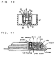
- Fig. 11 shows an electric motor, for instance a spindle motor.
- the motor comprises a spindle, a hub as rotor, a flange as base, and a yoke holder.
- the spindle is supported in a ball bearing, which comprises an inner and an outer ring provided in a bearing sleeve.
- These components are provided as independent parts, and such components as the hub, flange, yoke holder, etc. are separate parts from the ball bearing.
- the prior art motor comprises the hub, flange and yoke holder as separate parts from the ball bearing, it has a large number of components. Besides, in manufacture a step of assembling the components on the ball bearing is necessary. The manufacture thus involves a large number of steps and leads to a high cost.
- An object of the invention is to provide an electric motor, particularly, a spindle motor, which comprises a reduced number of components and can reduce the steps of assembling to permit reduction of the cost of manufacture to be expected, as well as permitting improvement of the race-way run-out with side.
- a hub as rotor, a flange as base or a stator yoke holder is molded together with a sleeve, a spindle or an inner ring of a bearing body.
- an integral bearing type electric motor which comprises a bearing body including a spindle, a sleeve surrounding the spindle, an inner or outer ring fitted in or on the spindle, and balls provided between the spindle and sleeve. between the spindle and outer ring or between the inner ring and sleeve, a hub for the rotor of the motor, a flange for the base of the motor or a stator yoke holder being formed by molding together with the sleeve, spindle or inner ring of the bearing body.
- an integral bearing type electric motor which comprises a bearing body including a stepped spindle having a large and a small diameter portion, a sleeve surrounding the spindle, the spindle having a large diameter portion thereof formed with an outer race for one ball row, balls in one row being provided between the outer race and an inner race formed in the sleeve, and an inner ring fitted on the small diameter portion of the spindle and having an outer race, balls in another row being provided between the inner ring outer race and a corresponding inner race formed in the sleeve, a hub of the motor being formed by molding together with the sleeve of spindle.
- an integral bearing type electric motor which comprises a bearing body including a stepped spindle having a large and a small diameter portion, a sleeve surrounding the spindle, the spindle having a large diameter portion thereof formed with an outer race for one ball row, balls in one row being provided between the outer race and an inner race formed in the sleeve, and an inner ring fitted on the small diameter portion of the spindle and having an outer race, balls in another row being provided between the inner ring outer race and a corresponding inner race formed in the sleeve, a flange as the base of the motor being formed by molding together with the sleeve or spindle of the bearing body.
- an integral bearing type electric motor which comprises a bearing body including a stepped spindle having a large and a small diameter portion, a sleeve surrounding the spindle, the spindle having a large diameter portion thereof formed with an outer race for one ball row, balls in one row being provided between the outer race and an inner race formed in the sleeve, and an inner ring fitted on the small diameter portion of the spindle and having an outer race, balls in another row being provided between the inner ring outer race and a corresponding inner race formed in the sleeve, a yoke holder having a yoke mounting rib formed on the outer periphery edge being formed by molding together with the sleeve of the bearing body.
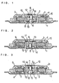
- Figs. 1 and 2 show outer rotor type spindle motors according to the invention.
- a flange 1 as base has its central portion provided with a cylindrical yoke holder , and a stator yoke 4 with a coil 3 is provided around the yoke holder.
- a spindle 5 is secured at its lower end to the center of the flange, more specifically the center of the bottom of a yoke holder 2.
- the spindle is a two-step spindle with a small diameter upper portion.
- the outer periphery of the lower large diameter portion of the spindle is formed with a race 6, and an inner ring 8 with a race 7 is fitted on the small diameter portion of the spindle.
- a hub 9 as rotor has a central integral sleeve 10 for a bearing body.
- the inner periphery of the sleeve 10 has juxtaposed races 11 and 12 respectively corresponding to the large diameter portion race of the spindle and the race of the inner ring.
- Balls 13 and 14 are provided between mating ones of the races.
- the sleeve 10, balls 13 and 14, inner ring 8 and race 6 of the large diameter portion of the spindle, form the ball bearing body, which supports the hub for rotation about the spindle.
- a magnet 15 for forming field magnetic flux is provided on the inner periphery of the hub such that it faces the yoke.
- a sleeve 10 for a ball bearing body is provided in a central portion of a flange 1.
- a spindle 5 is provided such that it is integral with the underside of a central portion of a hub 9.
- the spindle is a two-step one and vertically converse to that shown in Fig. 1, and structural relationship among spindle race 6, inner ring 8, race 7 thereof, sleeve races 11 and 12 and balls 13 and 14 is the same as that in the case of Fig. 1.
- the status yoke 4 is mounted on the sleeve 10, and the yoke holder 2 shown in Fig. 1 is dispensed with.
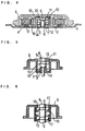
- Figs. 3 and 4 show inner rotor type spindle motors according to the invention.
- a two-step spindle 5 is erected from the bottom center of a stator yoke holder 2 having an outer flange 1.
- a stator yoke 4 is mounted in the inner periphery of a cylindrical rib 2a of the stator yoke holder.
- the sleeve 10 for the ball bearing body is formed such that it is integral with the center of the hub 10.
- the structure of the ball bearing body is the same as in the embodiment of Fig. 1, but a permanent magnet is provided on the outer periphery of the sleeve 10.
- a stator yoke holder 2 and sleeve 10 of the ball bearing body are integral with each other, and a spindle 5 and hub 9 are integral with each other.
- a stator yoke 4 is provided in the inner periphery of a rib 2a of the stator yoke holder 2, and a permanent magnet 15 is provided on the outer periphery of a cylindrical magnet holder 16, which is formed by molding such that it is integral with the center of the underside of the hub 9.
- the spindle is of two-step structure, and the ball bearing body is of the same structure as that in the embodiment shown in Fig. 2.
- the inner surface (top surface) of the flange is provided with a printed circuit board for motor driving in correspondence to the coil 3.
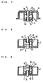
- a hub 9 and a sleeve 10 of ball bearing body are molded together to form a one-piece molding.
- the flange and sleeve 10 of ball bearing body are molded together.
- the flange and inner ring 8 of ball bearing body (which inner ring is integral with the flange) are molded together.
- the flange and spindle are molded together.
- the hub as rotor or the flange as base or the yoke holder is molded such that it is integral with the sleeve or spindle or inner or outer ring of the bearing body.
- the hub or flange or yoke holder is a separate part from the bearing body, assembling at the time of the manufacture can be readily made, efficient assembling can be obtained by using machines, and the cost of manufacture can be reduced. which are very beneficial in the industrial production.
- At least one of such parts as the hub. flange and yoke holder is preliminarily molded together with the sleeve, spindle, inner ring or outer ring of the ball bearing body.
- the composite bearing has an advantage in manufacture that pre-loading can be readily effected by urging the inner and outer rings to each other in their axial direction.
Landscapes
- Engineering & Computer Science (AREA)
- Power Engineering (AREA)
- General Engineering & Computer Science (AREA)
- Mechanical Engineering (AREA)
- Motor Or Generator Frames (AREA)
- Permanent Magnet Type Synchronous Machine (AREA)
- Brushless Motors (AREA)
Priority Applications (1)
| Application Number | Priority Date | Filing Date | Title |
|---|---|---|---|
| EP00101617A EP0998012A1 (de) | 1992-11-09 | 1993-11-09 | Elektrischer Motor des Typs mit intergriertem Lager |
Applications Claiming Priority (4)
| Application Number | Priority Date | Filing Date | Title |
|---|---|---|---|
| JP323645/92 | 1992-11-09 | ||
| JP32364592 | 1992-11-09 | ||
| JP4323645A JP2890157B2 (ja) | 1992-11-09 | 1992-11-09 | Oa機器用の複合軸受電動機 |
| EP93308952A EP0597678B1 (de) | 1992-11-09 | 1993-11-09 | Elektrischer Motor des Typs mit integriertem Lager |
Related Parent Applications (2)
| Application Number | Title | Priority Date | Filing Date |
|---|---|---|---|
| EP93308952A Division EP0597678B1 (de) | 1992-11-09 | 1993-11-09 | Elektrischer Motor des Typs mit integriertem Lager |
| EP93308952.6 Division | 1993-11-09 |
Related Child Applications (1)
| Application Number | Title | Priority Date | Filing Date |
|---|---|---|---|
| EP00101617A Division EP0998012A1 (de) | 1992-11-09 | 1993-11-09 | Elektrischer Motor des Typs mit intergriertem Lager |
Publications (2)
| Publication Number | Publication Date |
|---|---|
| EP0790694A1 true EP0790694A1 (de) | 1997-08-20 |
| EP0790694B1 EP0790694B1 (de) | 2001-08-29 |
Family
ID=18157038
Family Applications (3)
| Application Number | Title | Priority Date | Filing Date |
|---|---|---|---|
| EP00101617A Withdrawn EP0998012A1 (de) | 1992-11-09 | 1993-11-09 | Elektrischer Motor des Typs mit intergriertem Lager |
| EP97201208A Expired - Lifetime EP0790694B1 (de) | 1992-11-09 | 1993-11-09 | Elektrischer Motor des Typs mit integriertem Lager |
| EP93308952A Expired - Lifetime EP0597678B1 (de) | 1992-11-09 | 1993-11-09 | Elektrischer Motor des Typs mit integriertem Lager |
Family Applications Before (1)
| Application Number | Title | Priority Date | Filing Date |
|---|---|---|---|
| EP00101617A Withdrawn EP0998012A1 (de) | 1992-11-09 | 1993-11-09 | Elektrischer Motor des Typs mit intergriertem Lager |
Family Applications After (1)
| Application Number | Title | Priority Date | Filing Date |
|---|---|---|---|
| EP93308952A Expired - Lifetime EP0597678B1 (de) | 1992-11-09 | 1993-11-09 | Elektrischer Motor des Typs mit integriertem Lager |
Country Status (3)
| Country | Link |
|---|---|
| EP (3) | EP0998012A1 (de) |
| JP (1) | JP2890157B2 (de) |
| DE (2) | DE69330687T2 (de) |
Families Citing this family (6)
| Publication number | Priority date | Publication date | Assignee | Title |
|---|---|---|---|---|
| JP2890158B2 (ja) * | 1992-10-07 | 1999-05-10 | ミネベア株式会社 | Oa機器用のモータ部品一体型複合玉軸受 |
| US5841210A (en) * | 1995-08-09 | 1998-11-24 | Minebea Kabushiki-Kaisha | Electric drive motor with a compound bearing assembly |
| US5798888A (en) * | 1997-04-09 | 1998-08-25 | Iomega Corporation | Disk hub for a removable cartridge and spindle motor for using same |
| JP2001309606A (ja) * | 2000-04-19 | 2001-11-02 | Minebea Co Ltd | Oa機器用の複合軸受電動機 |
| JP2002034198A (ja) * | 2000-07-18 | 2002-01-31 | Minebea Co Ltd | スピンドルモータ |
| DE102004040224B4 (de) * | 2004-08-19 | 2010-04-08 | Ab Skf | Wälzlager |
Citations (6)
| Publication number | Priority date | Publication date | Assignee | Title |
|---|---|---|---|---|
| FR2565017A1 (fr) * | 1984-05-26 | 1985-11-29 | Mueller Georg Nuernberg | Axe-moteur pour l'entrainement de memoires a disques magnetiques |
| DE3540363A1 (de) * | 1984-12-19 | 1986-06-19 | FAG Kugelfischer Georg Schäfer KGaA, 8720 Schweinfurt | Spindel, insbesondere plattenspeicherspindel |
| US4733120A (en) * | 1986-06-27 | 1988-03-22 | Tamagawa Seiki Kabushiki Kaisha | Flat type stepping motor |
| JPH03285546A (ja) * | 1990-03-30 | 1991-12-16 | Nippon Densan Corp | スピンドルモータ |
| WO1993006600A1 (en) * | 1991-09-25 | 1993-04-01 | Integral Peripherals, Inc. | Architecture for low-profile rigid disk drive |
| EP0592214A2 (de) * | 1992-10-07 | 1994-04-13 | Minebea Kabushiki-Kaisha | Compound-Kugellager |
Family Cites Families (9)
| Publication number | Priority date | Publication date | Assignee | Title |
|---|---|---|---|---|
| DE2404241C3 (de) * | 1974-01-30 | 1979-11-15 | Teldix Gmbh, 6900 Heidelberg | OE-Rotorspinneinheit |
| JP2599707B2 (ja) * | 1986-06-20 | 1997-04-16 | 株式会社日立製作所 | 磁気デイスク装置 |
| JPH0834030B2 (ja) * | 1987-04-13 | 1996-03-29 | 松下電器産業株式会社 | 記録円盤駆動装置 |
| US5045738A (en) * | 1989-02-22 | 1991-09-03 | Nippon Densan Corporation | Spindle motor |
| FR2648286B1 (fr) * | 1989-06-08 | 1992-02-07 | Rks | Couronne d'orientation a roulement a moteur integre |
| JPH0720362B2 (ja) * | 1989-10-31 | 1995-03-06 | 日本精工株式会社 | ハードディスク駆動用電動モータ |
| JPH04208052A (ja) * | 1990-11-30 | 1992-07-29 | Nippon Densan Corp | スピンドルモータ |
| JP3064441B2 (ja) * | 1991-01-31 | 2000-07-12 | 日本電産株式会社 | 軸受構造体及びスピンドルモータ |
| EP0524673B1 (de) * | 1991-07-05 | 1997-06-11 | Koninklijke Philips Electronics N.V. | Lagervorrichtung sowie Vorrichtung mit einer drehbaren Scheibe und ein Magnetbandgerät |
-
1992
- 1992-11-09 JP JP4323645A patent/JP2890157B2/ja not_active Expired - Lifetime
-
1993
- 1993-11-09 DE DE69330687T patent/DE69330687T2/de not_active Expired - Fee Related
- 1993-11-09 EP EP00101617A patent/EP0998012A1/de not_active Withdrawn
- 1993-11-09 DE DE69316713T patent/DE69316713T2/de not_active Expired - Fee Related
- 1993-11-09 EP EP97201208A patent/EP0790694B1/de not_active Expired - Lifetime
- 1993-11-09 EP EP93308952A patent/EP0597678B1/de not_active Expired - Lifetime
Patent Citations (6)
| Publication number | Priority date | Publication date | Assignee | Title |
|---|---|---|---|---|
| FR2565017A1 (fr) * | 1984-05-26 | 1985-11-29 | Mueller Georg Nuernberg | Axe-moteur pour l'entrainement de memoires a disques magnetiques |
| DE3540363A1 (de) * | 1984-12-19 | 1986-06-19 | FAG Kugelfischer Georg Schäfer KGaA, 8720 Schweinfurt | Spindel, insbesondere plattenspeicherspindel |
| US4733120A (en) * | 1986-06-27 | 1988-03-22 | Tamagawa Seiki Kabushiki Kaisha | Flat type stepping motor |
| JPH03285546A (ja) * | 1990-03-30 | 1991-12-16 | Nippon Densan Corp | スピンドルモータ |
| WO1993006600A1 (en) * | 1991-09-25 | 1993-04-01 | Integral Peripherals, Inc. | Architecture for low-profile rigid disk drive |
| EP0592214A2 (de) * | 1992-10-07 | 1994-04-13 | Minebea Kabushiki-Kaisha | Compound-Kugellager |
Non-Patent Citations (1)
| Title |
|---|
| PATENT ABSTRACTS OF JAPAN vol. 16, no. 116 (E - 1181) 24 March 1992 (1992-03-24) * |
Also Published As
| Publication number | Publication date |
|---|---|
| DE69330687T2 (de) | 2002-06-27 |
| EP0790694B1 (de) | 2001-08-29 |
| EP0597678B1 (de) | 1998-01-28 |
| DE69330687D1 (de) | 2001-10-04 |
| DE69316713D1 (de) | 1998-03-05 |
| EP0998012A1 (de) | 2000-05-03 |
| EP0597678A1 (de) | 1994-05-18 |
| JPH06153447A (ja) | 1994-05-31 |
| JP2890157B2 (ja) | 1999-05-10 |
| DE69316713T2 (de) | 1998-06-18 |
Similar Documents
| Publication | Publication Date | Title |
|---|---|---|
| US5698919A (en) | Integral bearing type electric motor | |
| EP0762610B1 (de) | Kompound Kugellager | |
| US4755709A (en) | Electric machine having magnetic bearing means | |
| US4884000A (en) | Brushless DC motor inner tachometer | |
| US8449268B2 (en) | Fan and method for manufacturing the same | |
| EP0620633A1 (de) | Motor | |
| JP3312942B2 (ja) | 磁気ディスク装置 | |
| EP0790694A1 (de) | Elektrischer Motor des Typs mit integriertem Lager | |
| EP0758155B1 (de) | Elektrischer Antriebsmotor mit mehrteiligem Lager | |
| EP0310391B1 (de) | Axiallüfter | |
| US6467962B1 (en) | Metal bearing and method of manufacturing the same | |
| US20010033705A1 (en) | Motor with compound bearing for OA device | |
| EP0770998A1 (de) | Festplattenantrieb mit zusammengesetzter Lagereinheit | |
| JPH0538118A (ja) | 無刷子電動機 | |
| JPS5972956A (ja) | 光偏向用モ−タ | |
| JP3003308U (ja) | 回転電機の軸受支持構造 | |
| CN217720859U (zh) | 一种电机组件及应用该电机组件的电机 | |
| KR100287618B1 (ko) | 스핀들 모터_ | |
| JP2002112507A (ja) | ブラシレスモータ | |
| JPH09219953A (ja) | スピンドルモータ | |
| JPH0570161U (ja) | モータ | |
| JP3029380U (ja) | モータのステータ固定構造 | |
| JPH05252703A (ja) | モータの軸受取付方法とモータ | |
| JPH09154270A (ja) | ブラシレスモータ | |
| KR20020000419A (ko) | 편평형 진동모터 |
Legal Events
| Date | Code | Title | Description |
|---|---|---|---|
| PUAI | Public reference made under article 153(3) epc to a published international application that has entered the european phase |
Free format text: ORIGINAL CODE: 0009012 |
|
| AC | Divisional application: reference to earlier application |
Ref document number: 597678 Country of ref document: EP |
|
| AK | Designated contracting states |
Kind code of ref document: A1 Designated state(s): DE FR GB IT |
|
| 17P | Request for examination filed |
Effective date: 19980123 |
|
| 17Q | First examination report despatched |
Effective date: 19991008 |
|
| GRAG | Despatch of communication of intention to grant |
Free format text: ORIGINAL CODE: EPIDOS AGRA |
|
| GRAG | Despatch of communication of intention to grant |
Free format text: ORIGINAL CODE: EPIDOS AGRA |
|
| GRAG | Despatch of communication of intention to grant |
Free format text: ORIGINAL CODE: EPIDOS AGRA |
|
| GRAH | Despatch of communication of intention to grant a patent |
Free format text: ORIGINAL CODE: EPIDOS IGRA |
|
| GRAH | Despatch of communication of intention to grant a patent |
Free format text: ORIGINAL CODE: EPIDOS IGRA |
|
| GRAA | (expected) grant |
Free format text: ORIGINAL CODE: 0009210 |
|
| AC | Divisional application: reference to earlier application |
Ref document number: 597678 Country of ref document: EP |
|
| AK | Designated contracting states |
Kind code of ref document: B1 Designated state(s): DE FR GB IT |
|
| REF | Corresponds to: |
Ref document number: 69330687 Country of ref document: DE Date of ref document: 20011004 |
|
| REG | Reference to a national code |
Ref country code: GB Ref legal event code: IF02 |
|
| EN | Fr: translation not filed | ||
| PLBE | No opposition filed within time limit |
Free format text: ORIGINAL CODE: 0009261 |
|
| STAA | Information on the status of an ep patent application or granted ep patent |
Free format text: STATUS: NO OPPOSITION FILED WITHIN TIME LIMIT |
|
| 26N | No opposition filed | ||
| ET | Fr: translation filed | ||
| REG | Reference to a national code |
Ref country code: FR Ref legal event code: ERR Free format text: BOPI DE PUBLICATION N: 02/04 PAGES: 243 PARTIE DU BULLETIN CONCERNEE: BREVETS EUROPEENS DONT LA TRADUCTION N'A PAS ETE REMISE A I'INPI IL Y A LIEU DE SUPPRIMER: LA MENTION DE LA NON REMISE. LA REMISE DE LA TRADUCTION EST PUBLIEE DANS LE PRESENT BOPI. |
|
| PGFP | Annual fee paid to national office [announced via postgrant information from national office to epo] |
Ref country code: DE Payment date: 20081107 Year of fee payment: 16 |
|
| PGFP | Annual fee paid to national office [announced via postgrant information from national office to epo] |
Ref country code: IT Payment date: 20081127 Year of fee payment: 16 |
|
| PGFP | Annual fee paid to national office [announced via postgrant information from national office to epo] |
Ref country code: FR Payment date: 20081112 Year of fee payment: 16 |
|
| PGFP | Annual fee paid to national office [announced via postgrant information from national office to epo] |
Ref country code: GB Payment date: 20081105 Year of fee payment: 16 |
|
| GBPC | Gb: european patent ceased through non-payment of renewal fee |
Effective date: 20091109 |
|
| REG | Reference to a national code |
Ref country code: FR Ref legal event code: ST Effective date: 20100730 |
|
| PG25 | Lapsed in a contracting state [announced via postgrant information from national office to epo] |
Ref country code: FR Free format text: LAPSE BECAUSE OF NON-PAYMENT OF DUE FEES Effective date: 20091130 |
|
| PG25 | Lapsed in a contracting state [announced via postgrant information from national office to epo] |
Ref country code: DE Free format text: LAPSE BECAUSE OF NON-PAYMENT OF DUE FEES Effective date: 20100601 |
|
| PG25 | Lapsed in a contracting state [announced via postgrant information from national office to epo] |
Ref country code: GB Free format text: LAPSE BECAUSE OF NON-PAYMENT OF DUE FEES Effective date: 20091109 |
|
| PG25 | Lapsed in a contracting state [announced via postgrant information from national office to epo] |
Ref country code: IT Free format text: LAPSE BECAUSE OF NON-PAYMENT OF DUE FEES Effective date: 20091109 |