EP0310481A1 - Vorrichtung zum Verfahren eines Auslegers, insbesondere eines Handhabungsgreifers in vertikaler Richtung - Google Patents
Vorrichtung zum Verfahren eines Auslegers, insbesondere eines Handhabungsgreifers in vertikaler Richtung Download PDFInfo
- Publication number
- EP0310481A1 EP0310481A1 EP88402407A EP88402407A EP0310481A1 EP 0310481 A1 EP0310481 A1 EP 0310481A1 EP 88402407 A EP88402407 A EP 88402407A EP 88402407 A EP88402407 A EP 88402407A EP 0310481 A1 EP0310481 A1 EP 0310481A1
- Authority
- EP
- European Patent Office
- Prior art keywords
- carriage
- track
- plates
- shaped irons
- rails
- Prior art date
- Legal status (The legal status is an assumption and is not a legal conclusion. Google has not performed a legal analysis and makes no representation as to the accuracy of the status listed.)
- Granted
Links
Images

Classifications
-
- B—PERFORMING OPERATIONS; TRANSPORTING
- B25—HAND TOOLS; PORTABLE POWER-DRIVEN TOOLS; MANIPULATORS
- B25J—MANIPULATORS; CHAMBERS PROVIDED WITH MANIPULATION DEVICES
- B25J9/00—Program-controlled manipulators
- B25J9/02—Program-controlled manipulators characterised by movement of the arms, e.g. cartesian coordinate type
- B25J9/023—Cartesian coordinate type
-
- B—PERFORMING OPERATIONS; TRANSPORTING
- B25—HAND TOOLS; PORTABLE POWER-DRIVEN TOOLS; MANIPULATORS
- B25J—MANIPULATORS; CHAMBERS PROVIDED WITH MANIPULATION DEVICES
- B25J9/00—Program-controlled manipulators
- B25J9/10—Program-controlled manipulators characterised by positioning means for manipulator elements
- B25J9/104—Program-controlled manipulators characterised by positioning means for manipulator elements with cables, chains or ribbons
Definitions
- the invention relates to a device for moving a mobile comprising a first carriage movable along a first track, and a second carriage carrying the mobile movable along a second track intersecting from the first.
- the object of the invention is to remedy these drawbacks and to do this the second carriage extends on either side of the first and is moved by a fixed motor member which drives a flexible element formed by two strands extending from on the other side of the first track and immobilized at their end opposite to the drive member, each strand passing over first return members mounted on the first carriage on either side of the second track and over second members return mounted on the second carriage beyond the first.
- the flexible element always comprises an absorbed strand and a delivered strand, the absorbed length being strictly equal to the delivered length.
- the flexible element is therefore always under tension and there is no longer any need to limit either the speeds, the accelerations or the braking.
- the device can work in all planes.
- the motor member is fixed. Neither the first track, nor the second track, nor either of the two carriages has to support the weight and the bulk of this drive member.
- the first carriage consists of four plates facing two by two to form a tunnel for the second carriage, two of the plates carrying external rolling members cooperating with rails carried by two fixed U-irons to form the first track, the other two plates bearing internal rolling members cooperating with rails integral with the second carriage to form the second track, the fixed U-shaped irons, braced by an end plate, containing the means for moving the first carriage, while the second carriage is constituted by two opposite U-shaped irons, the bases of which receive the rails of the second track, joined by plates extending beyond the U-shaped irons, which in turn receive end plates, one of which carries the mobile.
- the deflection members are mounted at the ends of the plates of the first carriage carrying the second rolling members and between the ends of the plates of the second carriage, beyond the U-shaped irons, the strands of the flexible element skirting the second carriage extending at the level of the openings of the U-shaped irons.
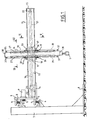
- the device shown was designed to move a mobile constituted here by the gripper 1 in the plane of Figure 1. It is mounted on a bracket 2, itself equipped with ball bushings 3 carried by supports 4 and cooperating with rails 5 carried by supports 6 integral with columns 7 fixed to the ground at 8.
- This conventional arrangement makes it possible to move the device in planes parallel to that of FIG. 1 and thus to cover, for example, a whole handling or storage space, the stem 2 being moved by a motor 9, the pinion 10 of which collaborates with a toothed belt 11.
- the first track 12 of the device consists of two U-shaped irons 13 facing each other mounted on the plate 14 of the console 2 and joined by an end plate 15 which ensures rigidity.
- the U-shaped irons 13 receive rails 16 which collaborate with ball bushings 17 carried by longitudinal plates 18 welded on the edges of two transverse plates 19 to constitute the first carriage 20.
- the drive of the first carriage 20 is ensured by a belt 21 circulating in one of the U-shaped irons 13, between an end pulley 22 and a drive motor 23.
- the pulley 22 is mounted in the U-shaped iron 13, near its end.
- the motor 23 is mounted fixed at the other end and therefore rests on the plate 14.
- the belt 21 is fixed on an anchor 24 integral with one of the plates 18 and therefore with the first carriage 20.
- the second track 25 consists of four ball bushings 26 arranged vertically inside the carriage 20 on the plates 19, which cooperate with vertical rails 27 integral with the second carriage 28 formed by the union of two U-shaped irons 29, containing the rails 27 and the ball bushings 26, joined by two plates 30 which, for reasons which will be explained below, extend slightly beyond the U-shaped irons 29.
- the belt 31 which ensures the movements in one direction or another of the second carriage 28 is driven by a motor 32 placed beyond the motor 23 on the plate 14 and anchored at its two ends on the end plate 15.
- the upper strand of the belt 31 forms a loop thanks to two pulleys 33 mounted on arms 34 at the upper ends of the plates 19 and to two other pulleys 35 carried by the portions of the plates 30 which extend beyond the U-shaped irons. 29.
- the lower strand of the belt 31 forms a similar loop by virtue of two symmetrical pulleys 36 of the pulleys 33 and two symmetrical pulleys 37 of the pulleys 35.
- the axes and dimensions of the pulleys 33, 35, 36 and 37 have been chosen such that the paths of the belt 31 are horizontal and vertical and that, in addition, the vertical strands are, at least approximately, at the level of the openings of the U-shaped irons 29.
- This arrangement greatly improves the aesthetics of the apparatus and protects the internal part of the U-shaped irons open towards the outside from any dirt in cooperation with the end plates 38 welded on plates 30 and one of which carries the gripper 1.
- the three motors allowing all the movements of the gripper 1 in the plane of FIG. 1 and in any parallel plane are carried by the bracket 2.
- the first carriage 20 does not carry any motor and the device is therefore much lighter, much cheaper and more aesthetic than those existing, in which the motor ensuring the movements of the second carriage is carried by the first.
- the travel speeds and the accelerations or braking of the carriages and therefore of the load are not subject to limitations since the belts are always under tension without the need for additional mass.
Landscapes
- Engineering & Computer Science (AREA)
- Robotics (AREA)
- Mechanical Engineering (AREA)
- Manipulator (AREA)
- Load-Engaging Elements For Cranes (AREA)
- Forklifts And Lifting Vehicles (AREA)
- Carriers, Traveling Bodies, And Overhead Traveling Cranes (AREA)
Priority Applications (1)
| Application Number | Priority Date | Filing Date | Title |
|---|---|---|---|
| AT88402407T ATE85931T1 (de) | 1987-10-02 | 1988-09-23 | Vorrichtung zum verfahren eines auslegers, insbesondere eines handhabungsgreifers in vertikaler richtung. |
Applications Claiming Priority (2)
| Application Number | Priority Date | Filing Date | Title |
|---|---|---|---|
| FR8713653 | 1987-10-02 | ||
| FR8713653A FR2621271A1 (fr) | 1987-10-02 | 1987-10-02 | Dispositif pour deplacer un mobile, et en particulier un prehenseur de manutention dans un plan vertical |
Publications (2)
| Publication Number | Publication Date |
|---|---|
| EP0310481A1 true EP0310481A1 (de) | 1989-04-05 |
| EP0310481B1 EP0310481B1 (de) | 1993-02-24 |
Family
ID=9355470
Family Applications (1)
| Application Number | Title | Priority Date | Filing Date |
|---|---|---|---|
| EP88402407A Expired - Lifetime EP0310481B1 (de) | 1987-10-02 | 1988-09-23 | Vorrichtung zum Verfahren eines Auslegers, insbesondere eines Handhabungsgreifers in vertikaler Richtung |
Country Status (5)
| Country | Link |
|---|---|
| EP (1) | EP0310481B1 (de) |
| AT (1) | ATE85931T1 (de) |
| DE (1) | DE3878621T2 (de) |
| ES (1) | ES2039669T3 (de) |
| FR (1) | FR2621271A1 (de) |
Cited By (11)
| Publication number | Priority date | Publication date | Assignee | Title |
|---|---|---|---|---|
| DE3926670A1 (de) * | 1989-08-11 | 1991-02-14 | Siemens Ag | Handhabungseinrichtung |
| WO1991018718A1 (en) * | 1990-06-05 | 1991-12-12 | Pharmacia Biosensor Ab | Liquid handling apparatus |
| US5100286A (en) * | 1989-09-08 | 1992-03-31 | Robotic Originals, Inc. | Robotic apparatus |
| FR2676955A1 (fr) * | 1991-05-31 | 1992-12-04 | Faveyrial Maurice | Robot manipulateur cartesien incorporant des moyens de transmission a courroie. |
| FR2682909A1 (fr) * | 1991-10-25 | 1993-04-30 | Arilon | Robot industriel a cadence elevee pour le deplacement d'un outil suivant les trois axes d'un repere cartesien orthogonal. |
| US5265490A (en) * | 1991-03-20 | 1993-11-30 | Canon Kabushiki Kaisha | Orthogonal two-axis moving apparatus |
| WO1996037346A1 (en) * | 1995-05-23 | 1996-11-28 | Vittorio Guarini | A transmission device with two or more axes and with stationary motors |
| WO1996038270A1 (en) * | 1995-06-02 | 1996-12-05 | Ats Automation Tooling Systems Inc. | Two-axis robot |
| WO2005009690A3 (en) * | 2003-06-30 | 2005-03-17 | Roboxis B V | Cartesian coordinates type robot |
| CN102990641A (zh) * | 2012-11-26 | 2013-03-27 | 哈尔滨工程大学 | 一种可移动物体定位取放装置 |
| CN104260077A (zh) * | 2014-09-19 | 2015-01-07 | 常熟市惠一机电有限公司 | 一种横行伺服单截机械手 |
Families Citing this family (2)
| Publication number | Priority date | Publication date | Assignee | Title |
|---|---|---|---|---|
| ES2229898B1 (es) * | 2003-05-16 | 2006-07-01 | Jose Miguel Sanchez Soler | Mecanismo de desplazamiento cartesiano, con transmision unica y doble accionamiento. |
| CN105127992B (zh) * | 2015-10-08 | 2018-03-13 | 广东工业大学 | 快递无人机货物自动装卸及配重平台 |
Citations (7)
| Publication number | Priority date | Publication date | Assignee | Title |
|---|---|---|---|---|
| US2679940A (en) * | 1951-06-28 | 1954-06-01 | Atomic Energy Commission | Electrical manipulator |
| GB1226936A (de) * | 1969-09-03 | 1971-03-31 | ||
| US3575301A (en) * | 1968-01-02 | 1971-04-20 | Ibm | Manipulator |
| WO1983002106A1 (en) * | 1981-12-08 | 1983-06-23 | Hutchins, Burleigh, M. | Robot and control system |
| DE3215700A1 (de) * | 1982-04-27 | 1983-10-27 | Siemens AG, 1000 Berlin und 8000 München | Handhabungseinrichtung, insbesondere zum bestuecken, entladen und transportieren von werkstuecken |
| FR2587927A1 (fr) * | 1985-09-27 | 1987-04-03 | Telemecanique Electrique | Systeme de transmission pour amener une tete active en regard de tout point d'une surface de travail |
| FR2590560A1 (fr) * | 1985-11-26 | 1987-05-29 | Guilbaud Jean Pierre | Dispositif de commande mecanique par cable du deplacement d'un objet dans l'espace |
-
1987
- 1987-10-02 FR FR8713653A patent/FR2621271A1/fr not_active Withdrawn
-
1988
- 1988-09-23 DE DE8888402407T patent/DE3878621T2/de not_active Expired - Fee Related
- 1988-09-23 AT AT88402407T patent/ATE85931T1/de not_active IP Right Cessation
- 1988-09-23 EP EP88402407A patent/EP0310481B1/de not_active Expired - Lifetime
- 1988-09-23 ES ES198888402407T patent/ES2039669T3/es not_active Expired - Lifetime
Patent Citations (7)
| Publication number | Priority date | Publication date | Assignee | Title |
|---|---|---|---|---|
| US2679940A (en) * | 1951-06-28 | 1954-06-01 | Atomic Energy Commission | Electrical manipulator |
| US3575301A (en) * | 1968-01-02 | 1971-04-20 | Ibm | Manipulator |
| GB1226936A (de) * | 1969-09-03 | 1971-03-31 | ||
| WO1983002106A1 (en) * | 1981-12-08 | 1983-06-23 | Hutchins, Burleigh, M. | Robot and control system |
| DE3215700A1 (de) * | 1982-04-27 | 1983-10-27 | Siemens AG, 1000 Berlin und 8000 München | Handhabungseinrichtung, insbesondere zum bestuecken, entladen und transportieren von werkstuecken |
| FR2587927A1 (fr) * | 1985-09-27 | 1987-04-03 | Telemecanique Electrique | Systeme de transmission pour amener une tete active en regard de tout point d'une surface de travail |
| FR2590560A1 (fr) * | 1985-11-26 | 1987-05-29 | Guilbaud Jean Pierre | Dispositif de commande mecanique par cable du deplacement d'un objet dans l'espace |
Cited By (13)
| Publication number | Priority date | Publication date | Assignee | Title |
|---|---|---|---|---|
| DE3926670A1 (de) * | 1989-08-11 | 1991-02-14 | Siemens Ag | Handhabungseinrichtung |
| US5100286A (en) * | 1989-09-08 | 1992-03-31 | Robotic Originals, Inc. | Robotic apparatus |
| WO1991018718A1 (en) * | 1990-06-05 | 1991-12-12 | Pharmacia Biosensor Ab | Liquid handling apparatus |
| US5265490A (en) * | 1991-03-20 | 1993-11-30 | Canon Kabushiki Kaisha | Orthogonal two-axis moving apparatus |
| FR2676955A1 (fr) * | 1991-05-31 | 1992-12-04 | Faveyrial Maurice | Robot manipulateur cartesien incorporant des moyens de transmission a courroie. |
| EP0546592A1 (de) * | 1991-10-25 | 1993-06-16 | Arilon | Industrieroboter mit hoher Kadenz zum Bewegen eines Werkzeuges in drei orthogonale kartesische Achsrichtungen |
| FR2682909A1 (fr) * | 1991-10-25 | 1993-04-30 | Arilon | Robot industriel a cadence elevee pour le deplacement d'un outil suivant les trois axes d'un repere cartesien orthogonal. |
| WO1996037346A1 (en) * | 1995-05-23 | 1996-11-28 | Vittorio Guarini | A transmission device with two or more axes and with stationary motors |
| WO1996038270A1 (en) * | 1995-06-02 | 1996-12-05 | Ats Automation Tooling Systems Inc. | Two-axis robot |
| WO2005009690A3 (en) * | 2003-06-30 | 2005-03-17 | Roboxis B V | Cartesian coordinates type robot |
| CN102990641A (zh) * | 2012-11-26 | 2013-03-27 | 哈尔滨工程大学 | 一种可移动物体定位取放装置 |
| CN102990641B (zh) * | 2012-11-26 | 2015-12-02 | 哈尔滨工程大学 | 一种可移动物体定位取放装置 |
| CN104260077A (zh) * | 2014-09-19 | 2015-01-07 | 常熟市惠一机电有限公司 | 一种横行伺服单截机械手 |
Also Published As
| Publication number | Publication date |
|---|---|
| DE3878621T2 (de) | 1993-09-23 |
| EP0310481B1 (de) | 1993-02-24 |
| DE3878621D1 (de) | 1993-04-01 |
| ES2039669T3 (es) | 1993-10-01 |
| ATE85931T1 (de) | 1993-03-15 |
| FR2621271A1 (fr) | 1989-04-07 |
Similar Documents
| Publication | Publication Date | Title |
|---|---|---|
| EP0310481B1 (de) | Vorrichtung zum Verfahren eines Auslegers, insbesondere eines Handhabungsgreifers in vertikaler Richtung | |
| EP0907546B1 (de) | Zusammengesetzte gelenkkupplung zwischen zwei wagenteilen eines nahverkersfahrzeuges, die durch ein von einer achse getragenem zwischenmodul getrennt sind | |
| CH639043A5 (fr) | Installation pour l'enlevement et la reception automatiques de charges par l'intermediaire de vehicules de transport. | |
| FR2576583A1 (fr) | Chariot a plateau inclinable, notamment pour machines de triage | |
| EP0493219A1 (de) | Ablenkvorrichtung für auf einem Förderer zirkulierende Objekte | |
| CA2640530A1 (fr) | Dispositif de manutention | |
| FR2622560A1 (fr) | Machine de stockage et de retrait de bacs de manutention | |
| FR2586212A1 (fr) | Robot industriel pour la manutention de pieces d'ouvrage et d'outils | |
| FR2567380A1 (fr) | Magasin rotatif a rayonnages. | |
| FR2533519A1 (fr) | Convoyeur et son dispositif de poussee | |
| EP0187552A1 (de) | Seilschwebebahn | |
| FR2686592A1 (fr) | Appareil pour desservir des rayonnages. | |
| EP0506551B1 (de) | Speicherförderer | |
| FR2507582A1 (fr) | Systeme de convoyeurs du type " power and free " | |
| FR2576000A1 (fr) | Convoyeur a chaines permettant d'accumuler des chariots sur un troncon du convoyeur | |
| FR2679513A1 (fr) | Mecanisme de propulsion, notamment pour fauteuil roulant. | |
| CA1024824A (en) | Continuous variable speed control system for travelling railings | |
| EP0063792B1 (de) | Antriebsvorrichtung zur Erzeugung einer progressiven zweiseitigen Bewegung eines auf geradlinigen Schienen geführten Organs | |
| CH673015A5 (en) | Structure of track for vehicles suspended from catenary - has rails hung from strengthening cable to exert prestress through vertical primary droppers on carrier cable | |
| FR2578522A1 (fr) | Dispositif de retournement de corps plats | |
| EP0310511A1 (de) | Transporteinrichtung für Produkte zur Bestrahlung, insbesondere für Nahrungsmittelprodukte | |
| FR2528815A1 (fr) | Appareil du genre destine a etre accole a une construction pour le transfert de charges selon des directions verticale et transversale | |
| EP0570262B1 (de) | Fördervorrichtung für Lastträger | |
| CH683167A5 (fr) | Installation de transport. | |
| FR2491899A1 (fr) | Appareil pour transferer des plateaux ou autres |
Legal Events
| Date | Code | Title | Description |
|---|---|---|---|
| PUAI | Public reference made under article 153(3) epc to a published international application that has entered the european phase |
Free format text: ORIGINAL CODE: 0009012 |
|
| AK | Designated contracting states |
Kind code of ref document: A1 Designated state(s): AT BE CH DE ES GB GR IT LI LU NL SE |
|
| 17P | Request for examination filed |
Effective date: 19891004 |
|
| 17Q | First examination report despatched |
Effective date: 19901112 |
|
| GRAA | (expected) grant |
Free format text: ORIGINAL CODE: 0009210 |
|
| AK | Designated contracting states |
Kind code of ref document: B1 Designated state(s): AT BE CH DE ES GB GR IT LI LU NL SE |
|
| PG25 | Lapsed in a contracting state [announced via postgrant information from national office to epo] |
Ref country code: SE Effective date: 19930224 Ref country code: GR Free format text: LAPSE BECAUSE OF FAILURE TO SUBMIT A TRANSLATION OF THE DESCRIPTION OR TO PAY THE FEE WITHIN THE PRESCRIBED TIME-LIMIT Effective date: 19930224 Ref country code: AT Effective date: 19930224 |
|
| REF | Corresponds to: |
Ref document number: 85931 Country of ref document: AT Date of ref document: 19930315 Kind code of ref document: T |
|
| REF | Corresponds to: |
Ref document number: 3878621 Country of ref document: DE Date of ref document: 19930401 |
|
| GBT | Gb: translation of ep patent filed (gb section 77(6)(a)/1977) |
Effective date: 19930408 |
|
| ITF | It: translation for a ep patent filed | ||
| PG25 | Lapsed in a contracting state [announced via postgrant information from national office to epo] |
Ref country code: GB Effective date: 19930923 |
|
| PG25 | Lapsed in a contracting state [announced via postgrant information from national office to epo] |
Ref country code: ES Free format text: LAPSE BECAUSE OF NON-PAYMENT OF DUE FEES Effective date: 19930924 |
|
| PG25 | Lapsed in a contracting state [announced via postgrant information from national office to epo] |
Ref country code: LU Free format text: LAPSE BECAUSE OF NON-PAYMENT OF DUE FEES Effective date: 19930930 Ref country code: LI Effective date: 19930930 Ref country code: CH Effective date: 19930930 Ref country code: BE Effective date: 19930930 |
|
| REG | Reference to a national code |
Ref country code: ES Ref legal event code: FG2A Ref document number: 2039669 Country of ref document: ES Kind code of ref document: T3 |
|
| PLBE | No opposition filed within time limit |
Free format text: ORIGINAL CODE: 0009261 |
|
| STAA | Information on the status of an ep patent application or granted ep patent |
Free format text: STATUS: NO OPPOSITION FILED WITHIN TIME LIMIT |
|
| 26N | No opposition filed | ||
| BERE | Be: lapsed |
Owner name: EUDE BERNARD CLAUDE PIERRE Effective date: 19930930 |
|
| PG25 | Lapsed in a contracting state [announced via postgrant information from national office to epo] |
Ref country code: NL Effective date: 19940401 |
|
| NLV4 | Nl: lapsed or anulled due to non-payment of the annual fee | ||
| GBPC | Gb: european patent ceased through non-payment of renewal fee |
Effective date: 19930923 |
|
| REG | Reference to a national code |
Ref country code: CH Ref legal event code: PL |
|
| PG25 | Lapsed in a contracting state [announced via postgrant information from national office to epo] |
Ref country code: DE Effective date: 19940601 |
|
| REG | Reference to a national code |
Ref country code: ES Ref legal event code: FD2A Effective date: 19941013 |
|
| PG25 | Lapsed in a contracting state [announced via postgrant information from national office to epo] |
Ref country code: IT Free format text: LAPSE BECAUSE OF NON-PAYMENT OF DUE FEES;WARNING: LAPSES OF ITALIAN PATENTS WITH EFFECTIVE DATE BEFORE 2007 MAY HAVE OCCURRED AT ANY TIME BEFORE 2007. THE CORRECT EFFECTIVE DATE MAY BE DIFFERENT FROM THE ONE RECORDED. Effective date: 20050923 |