EP0310726A1 - Verfahren zum Herstellen konischer Metalldosen und Werkzeug zur Durchführung des Verfahrens - Google Patents
Verfahren zum Herstellen konischer Metalldosen und Werkzeug zur Durchführung des Verfahrens Download PDFInfo
- Publication number
- EP0310726A1 EP0310726A1 EP87402240A EP87402240A EP0310726A1 EP 0310726 A1 EP0310726 A1 EP 0310726A1 EP 87402240 A EP87402240 A EP 87402240A EP 87402240 A EP87402240 A EP 87402240A EP 0310726 A1 EP0310726 A1 EP 0310726A1
- Authority
- EP
- European Patent Office
- Prior art keywords
- punch
- die
- blank
- stamping
- frustoconical
- Prior art date
- Legal status (The legal status is an assumption and is not a legal conclusion. Google has not performed a legal analysis and makes no representation as to the accuracy of the status listed.)
- Granted
Links
- 238000000034 method Methods 0.000 title claims abstract description 28
- 239000002184 metal Substances 0.000 title claims abstract description 21
- 229910052751 metal Inorganic materials 0.000 title claims abstract description 21
- 238000004519 manufacturing process Methods 0.000 title claims abstract description 10
- 239000011159 matrix material Substances 0.000 claims description 17
- 230000000712 assembly Effects 0.000 claims description 3
- 238000000429 assembly Methods 0.000 claims description 3
- 230000000295 complement effect Effects 0.000 claims description 3
- 230000015572 biosynthetic process Effects 0.000 description 4
- 238000000576 coating method Methods 0.000 description 3
- XEEYBQQBJWHFJM-UHFFFAOYSA-N Iron Chemical compound [Fe] XEEYBQQBJWHFJM-UHFFFAOYSA-N 0.000 description 2
- 230000005489 elastic deformation Effects 0.000 description 2
- 238000004806 packaging method and process Methods 0.000 description 2
- 208000031968 Cadaver Diseases 0.000 description 1
- 238000000137 annealing Methods 0.000 description 1
- 239000011324 bead Substances 0.000 description 1
- 230000000903 blocking effect Effects 0.000 description 1
- 239000011248 coating agent Substances 0.000 description 1
- 238000005034 decoration Methods 0.000 description 1
- 230000007547 defect Effects 0.000 description 1
- 229910052742 iron Inorganic materials 0.000 description 1
- 239000000463 material Substances 0.000 description 1
- 150000002739 metals Chemical class 0.000 description 1
- 238000011017 operating method Methods 0.000 description 1
- 235000011837 pasties Nutrition 0.000 description 1
- 238000004080 punching Methods 0.000 description 1
- 238000005482 strain hardening Methods 0.000 description 1
- 230000001131 transforming effect Effects 0.000 description 1
Images

Classifications
-
- B—PERFORMING OPERATIONS; TRANSPORTING
- B29—WORKING OF PLASTICS; WORKING OF SUBSTANCES IN A PLASTIC STATE IN GENERAL
- B29C—SHAPING OR JOINING OF PLASTICS; SHAPING OF MATERIAL IN A PLASTIC STATE, NOT OTHERWISE PROVIDED FOR; AFTER-TREATMENT OF THE SHAPED PRODUCTS, e.g. REPAIRING
- B29C51/00—Shaping by thermoforming, i.e. shaping sheets or sheet like preforms after heating, e.g. shaping sheets in matched moulds or by deep-drawing; Apparatus therefor
- B29C51/08—Deep drawing or matched-mould forming, i.e. using mechanical means only
-
- B—PERFORMING OPERATIONS; TRANSPORTING
- B21—MECHANICAL METAL-WORKING WITHOUT ESSENTIALLY REMOVING MATERIAL; PUNCHING METAL
- B21D—WORKING OR PROCESSING OF SHEET METAL OR METAL TUBES, RODS OR PROFILES WITHOUT ESSENTIALLY REMOVING MATERIAL; PUNCHING METAL
- B21D22/00—Shaping without cutting, by stamping, spinning, or deep-drawing
- B21D22/20—Deep-drawing
- B21D22/26—Deep-drawing for making peculiarly, e.g. irregularly, shaped articles
-
- B—PERFORMING OPERATIONS; TRANSPORTING
- B21—MECHANICAL METAL-WORKING WITHOUT ESSENTIALLY REMOVING MATERIAL; PUNCHING METAL
- B21D—WORKING OR PROCESSING OF SHEET METAL OR METAL TUBES, RODS OR PROFILES WITHOUT ESSENTIALLY REMOVING MATERIAL; PUNCHING METAL
- B21D51/00—Making hollow objects
- B21D51/16—Making hollow objects characterised by the use of the objects
- B21D51/26—Making hollow objects characterised by the use of the objects cans or tins; Closing same in a permanent manner
- B21D51/2646—Of particular non cylindrical shape, e.g. conical, rectangular, polygonal, bulged
Definitions
- the invention relates to a process for manufacturing frustoconical metal cans, by stamping and more particularly relates to such a process making it possible, if necessary, to use iron sheets called "double reduction". Such a sheet is remarkable for its increased hardness and rigidity allowing, for a desired mechanical strength of the box, to use a sheet of lesser thickness and therefore, to produce said box at a lower cost price.
- the invention also relates to a tool for implementing this method.
- Tapered metal packaging is increasingly appreciated by industrial users and consumers alike. Their main advantage resides in the fact that the box bodies can be stacked and therefore stored in a limited space between their manufacture and their filling. The packaging and transport of such box bodies thus stacked are therefore much less expensive. Likewise, the consumer, who uses a large number of such packages, may appreciate being able to stack them after use, before disposing of them. In addition, in the case where the boxes are filled with a pasty product, the release is facilitated by the frustoconical shape.
- the first phases consisting in producing a stepped blank formed by successive cylindrical portions of different diameters.
- the last phase consists of a frustoconical stamping of the kind indicated above. The same defects remain and are even accentuated, namely the formation of folds and the impossibility of using sheet metal called "double reduction".
- Another known method consists of stamping with a cylindrical die and a frustoconical punch, the metal gradually coming to conform to the shape of the frustoconical end of the punch.
- This process involves a significant tightening of the blank between the die and the blank holder so that the metal actually comes to match the shape of the punch. This therefore results in a high risk of damaging the interior and exterior coatings previously applied to the blank. In other words, we are forced to use very high quality coatings, very resistant and relatively expensive. On the other hand, this process is impractical with a sheet called "double reduction".
- a process derived from the previous one consists in first carrying out a conventional cylindrical blank before applying the stamping phase with cylindrical matrix and frustoconical punch. For box bodies exceeding a certain depth, a deep drawing is then carried out between die (s) and conical punch (s). This last process, the most recent, carrying out a certain combination of operating phases known individually, makes it possible to obtain a better surface condition (no crease) with sheets traditional. It remains impracticable with so-called "double reduction" sheets and one of its most serious drawbacks is the high pressure of blank holder required, which makes it difficult to use with pre-decorated blanks or blanks.
- the invention relates to a new stamping process for forming frustoconical box bodies having a remarkable surface condition (without creases) with a moderate blank holder pressure not damaging any decorated or varnished surface, applied before the stamping, on the blanks.
- Moderate blank holder pressure is understood to mean that usually used for cylindrical stampings and stampings, for example: - 15 to 20 bars for a first pass or a deep drawing made in a single pass - 40 to 60 bars for re-stamping passes.
- Another object of the invention is to propose a stamping process making it possible to form tapered box bodies from sheet blanks called "double reduction", of smaller thickness, all other things being equal.
- a "double reduction" sheet known per se, is defined as having undergone an additional work hardening phase after annealing, increasing its elastic deformation limit (greater than 480N / mm2) with the particularity of having a breaking limit fairly close to said elastic deformation limit, hence particular difficulties in transforming such a sheet, in particular by stamping.
- the invention essentially relates a method of manufacturing a frustoconical box body by stamping, of the type consisting in carrying out at least one phase of stamping a sheet blank or a blank derived from such a blank by applying said blank or blank look at the opening of a die with a predetermined clamping pressure and by making a punch penetrate into said die, characterized in that the or each stamping phase consists in making a punch essentially cylindrical in a essentially frustoconical die and in that said clamping pressure is low enough for the metal to substantially conform to the essentially frustoconical wall of said die, over at least part of the drawing depth.
- the invention also relates to a tool for the manufacture by stamping of a frustoconical box body, of the type comprising at least one punch-die assembly, said punch being capable of being forcibly engaged in said die through an opening in that by deforming a blank or a blank of sheet metal, said blank or blank being placed opposite the opening of said matrix and applied around this opening by clamping means, characterized in that the internal surface of said matrix is essentially frustoconical and that the punch is essentially cylindrical.
- the different punch-die assemblies are installed, for example, on a transfer press.
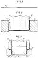
- Figures 1 to 5 there is shown in Figures 1 to 5 the main steps of a method of manufacturing a box body 11 ( Figure 5) by successive stampings of a blank 12 (Figure 2) originally in the form of substantially cylindrical bowl, itself obtained from a disc-shaped sheet blank 13 (FIG. 1).
- the blank 12 as visible in FIG. 2, is obtained by a first stamping of the blank 13, to a relatively shallow depth, by means of a punch 20 and a matrix 21, of complementary shapes, approximately cylindrical.
- This stamping phase is conventional and does not form part of the invention.
- the stamping ratio (ratio between the stamping depth and the diameter of the blank) is here sufficiently low so that the substantially cylindrical shape shown, can be obtained in a single punching phase, even with "double sheet” reduction".
- FIGS. 3 to 5 several successive stampings (three according to the example) of the blank 12 are made, which successively become 12 a , 12 b , 11, by subjecting it, each time, to action. of a punch-die set 30-31, 40-41 and 50-51, different.
- Each punch-matrix assembly is remarkable in that the diameter of the opening of the matrix D a , D b , D c increases from one phase to the other while the diameter d of the corresponding punch remains invariable.
- the conicity c of the matrix remains constant from one set to another.
- the diameter d is substantially equal to the final diameter of the bottom of the box body, practically completed at 11.
- the blank is applied opposite the opening of the matrix considered with a predetermined clamping pressure, applied by corresponding clamping means 32, 42, 52, in the form of a cylindrical annular ring.
- the clamping pressure is relatively moderate so that the metal substantially matches the internal wall of the die over the greater part of the drawing depth and no longer that of the punch, as it was the case in the prior art with conical punch. It is thus brought, in practice, to implement the usual clamping pressures for stamping and re-stamping of cylindrical bodies.
- the opening of the die like the end of the punch, does not have a sharp edge but, on the contrary, a rounded circular edge having in radial section, a certain radius of curvature.
- two parameters J and L can be defined here called respectively “annular clearance” and “free radial distance”.
- Ring play” J is defined as the half-difference between the diameter of the opening of the die (considering the latter as being the section of the extended frustoconical surface of said die with the plane of the entry face of this die) and the diameter of the punch, outside of its rounded end zone.
- the "free radial distance” L is defined as being the distance between the centers of curvature 0,0 ′, in radial section, of the edges of the opening of the die and the punch, in projection on a plane perpendicular to the axis common of the die and the punch.
- the "free radial distance” is therefore that over which the metal is not maintained at the start of its deformation.
- the "ring clearance” J and the “free radial distance” L should increase during successive stamping phases.
- Those skilled in the art can achieve similar conditions, in particular by judiciously choosing the annular clearances, the radii of curvature of the edge of the opening of the die on the one hand, and of the edge of the end of the punch on the other hand , this for a given material.
- a maximum drawing depth namely: where c represents the taper of the matrix (see figure 3) and e is the thickness of the sheet.
- the maximum drawing depth h max is therefore specific to each punch-die assembly and essentially depends on the clearance J.
- the actual drawing depth h is less than h max but the maximum h / h ratio increases between two consecutive stamping phases.
- this ratio successively increases as follows: 60% 80% 98%
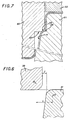
- FIG. 7 illustrates for example the punch-die assembly of FIG. 5 (of the last stamping phase) modified to cause a widening 55 in an upper annular portion of the box body 11.
- This widening forms a sort of shoulder thanks to which identical box bodies can be stacked without risk of blocking each other.
- the die 51 has a hollow annular zone 56 while the punch has an enlarged annular zone 57.
- the annular zones 56 and 57 are positioned so as to come opposite one another, at the end of the stroke of the punch 50 and their shapes and dimensions are such that they enclose and deform the metal so as to create the widening 55.
- the box body 11 undergoes a clipping of its upper edge; this classic operation has not been shown.
- the widening 55 which has the advantage of being obtained at the same time as the stamping, can be replaced by a circular bead, obtained by a specific internal knurling operation.
- the method defined above can be applied in a single phase, from a flat blank.
- the method is implemented with an essentially frustoconical matrix.
- the method can be implemented to obtain any form of box body comprising frustoconical sectors, for example frustoconical boxes or frustoconical boxes of cross section, elliptical or oval circular, using matrices of corresponding shapes .
Landscapes
- Engineering & Computer Science (AREA)
- Mechanical Engineering (AREA)
- Shaping Metal By Deep-Drawing, Or The Like (AREA)
- Forging (AREA)
- Containers Having Bodies Formed In One Piece (AREA)
Applications Claiming Priority (1)
| Application Number | Priority Date | Filing Date | Title |
|---|---|---|---|
| FR8612977A FR2603822B1 (fr) | 1986-09-17 | 1986-09-17 | Procede de fabrication de boites metalliques tronconiques et outillage pour la mise en oeuvre de ce procede |
Publications (2)
| Publication Number | Publication Date |
|---|---|
| EP0310726A1 true EP0310726A1 (de) | 1989-04-12 |
| EP0310726B1 EP0310726B1 (de) | 1991-12-27 |
Family
ID=9339023
Family Applications (1)
| Application Number | Title | Priority Date | Filing Date |
|---|---|---|---|
| EP87402240A Expired - Lifetime EP0310726B1 (de) | 1986-09-17 | 1987-10-08 | Verfahren zum Herstellen konischer Metalldosen und Werkzeug zur Durchführung des Verfahrens |
Country Status (6)
| Country | Link |
|---|---|
| EP (1) | EP0310726B1 (de) |
| AT (1) | ATE70747T1 (de) |
| DE (1) | DE3775561D1 (de) |
| ES (1) | ES2028898T3 (de) |
| FR (1) | FR2603822B1 (de) |
| GR (1) | GR3003698T3 (de) |
Cited By (9)
| Publication number | Priority date | Publication date | Assignee | Title |
|---|---|---|---|---|
| FR2710611A1 (fr) * | 1993-09-29 | 1995-04-07 | Pechiney Emballage Alimentaire | Capsules de surbouchage à jupe amincie et procédé de fabrication. |
| JP2006035225A (ja) * | 2004-07-22 | 2006-02-09 | Jfe Steel Kk | 傾斜側壁部を持つ金属製容器の成形方法 |
| CN107755445A (zh) * | 2017-10-19 | 2018-03-06 | 成都锦江电子系统工程有限公司 | 一种具有异形结构盒形件的引伸和挤压成型模具及方法 |
| CN110712359A (zh) * | 2019-11-20 | 2020-01-21 | 凌帕新能源科技(上海)有限公司 | 电池壳体及其成型方法、冲压装置 |
| EP3702061A1 (de) * | 2019-03-01 | 2020-09-02 | Adval Tech Holding AG | Verfahren zur herstellung von konischen metallobjekten |
| EP4101558A1 (de) | 2021-06-10 | 2022-12-14 | Adval Tech Holding AG | Verfahren zur herstellung eines aerosoldoms |
| WO2023174757A1 (de) | 2022-03-14 | 2023-09-21 | Adval Tech Holding Ag | Verfahren zur herstellung von konischen metallobjekten aus dünnen blechen |
| WO2024105098A1 (de) | 2022-11-18 | 2024-05-23 | Adval Tech Holding Ag | Verfahren zur herstellung eines aerosoldoms |
| WO2025201907A1 (de) | 2024-03-27 | 2025-10-02 | Adval Tech Holding Ag | Verfahren zur herstellung von konischen metallobjekten aus dünnen blechen und so hergestellte metallobjekte |
Families Citing this family (1)
| Publication number | Priority date | Publication date | Assignee | Title |
|---|---|---|---|---|
| GB2467178A (en) * | 2009-01-27 | 2010-07-28 | Wuu Shiang Ind Co Ltd | Forming a step in a sheet metal workpiece thereby reducing springback |
Citations (6)
| Publication number | Priority date | Publication date | Assignee | Title |
|---|---|---|---|---|
| GB207879A (en) * | 1922-09-07 | 1923-12-07 | Thomas Andrew Hayward | Improved method or arrangement of means for drawing and forming articles from sheet metal |
| US3302441A (en) * | 1963-07-09 | 1967-02-07 | Continental Can Co | Die for deep drawn tapered container |
| FR2340151A1 (fr) * | 1976-02-03 | 1977-09-02 | Haustrups Fabriker As | Procede et outillage pour la production par emboutissage de boites coniques en tole mince |
| US4051707A (en) * | 1976-02-02 | 1977-10-04 | Kraft, Inc. | Method and apparatus for making drawn containers |
| US4195510A (en) * | 1978-06-26 | 1980-04-01 | Juergens William A | Draw bead having alternating pressure surfaces and grooves |
| GB2096930A (en) * | 1981-04-22 | 1982-10-27 | Metal Box Co Ltd | Metal can bodies |
-
1986
- 1986-09-17 FR FR8612977A patent/FR2603822B1/fr not_active Expired - Lifetime
-
1987
- 1987-10-08 DE DE8787402240T patent/DE3775561D1/de not_active Expired - Fee Related
- 1987-10-08 ES ES198787402240T patent/ES2028898T3/es not_active Expired - Lifetime
- 1987-10-08 EP EP87402240A patent/EP0310726B1/de not_active Expired - Lifetime
- 1987-10-08 AT AT87402240T patent/ATE70747T1/de not_active IP Right Cessation
-
1992
- 1992-01-30 GR GR920400124T patent/GR3003698T3/el unknown
Patent Citations (6)
| Publication number | Priority date | Publication date | Assignee | Title |
|---|---|---|---|---|
| GB207879A (en) * | 1922-09-07 | 1923-12-07 | Thomas Andrew Hayward | Improved method or arrangement of means for drawing and forming articles from sheet metal |
| US3302441A (en) * | 1963-07-09 | 1967-02-07 | Continental Can Co | Die for deep drawn tapered container |
| US4051707A (en) * | 1976-02-02 | 1977-10-04 | Kraft, Inc. | Method and apparatus for making drawn containers |
| FR2340151A1 (fr) * | 1976-02-03 | 1977-09-02 | Haustrups Fabriker As | Procede et outillage pour la production par emboutissage de boites coniques en tole mince |
| US4195510A (en) * | 1978-06-26 | 1980-04-01 | Juergens William A | Draw bead having alternating pressure surfaces and grooves |
| GB2096930A (en) * | 1981-04-22 | 1982-10-27 | Metal Box Co Ltd | Metal can bodies |
Cited By (11)
| Publication number | Priority date | Publication date | Assignee | Title |
|---|---|---|---|---|
| FR2710611A1 (fr) * | 1993-09-29 | 1995-04-07 | Pechiney Emballage Alimentaire | Capsules de surbouchage à jupe amincie et procédé de fabrication. |
| JP2006035225A (ja) * | 2004-07-22 | 2006-02-09 | Jfe Steel Kk | 傾斜側壁部を持つ金属製容器の成形方法 |
| CN107755445A (zh) * | 2017-10-19 | 2018-03-06 | 成都锦江电子系统工程有限公司 | 一种具有异形结构盒形件的引伸和挤压成型模具及方法 |
| CN107755445B (zh) * | 2017-10-19 | 2023-12-05 | 成都锦江电子系统工程有限公司 | 一种具有异形结构盒形件的引伸和挤压成型模具及方法 |
| EP3702061A1 (de) * | 2019-03-01 | 2020-09-02 | Adval Tech Holding AG | Verfahren zur herstellung von konischen metallobjekten |
| CN110712359A (zh) * | 2019-11-20 | 2020-01-21 | 凌帕新能源科技(上海)有限公司 | 电池壳体及其成型方法、冲压装置 |
| CN110712359B (zh) * | 2019-11-20 | 2024-03-29 | 湖南领湃达志科技股份有限公司 | 电池壳体及其成型方法、冲压装置 |
| EP4101558A1 (de) | 2021-06-10 | 2022-12-14 | Adval Tech Holding AG | Verfahren zur herstellung eines aerosoldoms |
| WO2023174757A1 (de) | 2022-03-14 | 2023-09-21 | Adval Tech Holding Ag | Verfahren zur herstellung von konischen metallobjekten aus dünnen blechen |
| WO2024105098A1 (de) | 2022-11-18 | 2024-05-23 | Adval Tech Holding Ag | Verfahren zur herstellung eines aerosoldoms |
| WO2025201907A1 (de) | 2024-03-27 | 2025-10-02 | Adval Tech Holding Ag | Verfahren zur herstellung von konischen metallobjekten aus dünnen blechen und so hergestellte metallobjekte |
Also Published As
| Publication number | Publication date |
|---|---|
| FR2603822A1 (fr) | 1988-03-18 |
| ES2028898T3 (es) | 1992-07-16 |
| GR3003698T3 (de) | 1993-03-16 |
| ATE70747T1 (de) | 1992-01-15 |
| EP0310726B1 (de) | 1991-12-27 |
| DE3775561D1 (de) | 1992-02-06 |
| FR2603822B1 (fr) | 1992-11-13 |
Similar Documents
| Publication | Publication Date | Title |
|---|---|---|
| EP0451013B1 (de) | Verfahren und Vorrichtung zum Herstellen eines gewölbten Teils in einem Blechgegenstand und nach diesem Verfahren hergestellter Gegenstand | |
| FR2605911A1 (fr) | Procede et appareil pour former des pieces d'extremite de recipients | |
| EP0310726B1 (de) | Verfahren zum Herstellen konischer Metalldosen und Werkzeug zur Durchführung des Verfahrens | |
| FR2731929A1 (fr) | Procede de fabrication d'une boite metallique de forme | |
| FR2499884A1 (fr) | Recipient fabrique par emboutissage | |
| EP0363285B1 (de) | Leicht zu öffnende Flaschenkapsel aus Aluminiumfolie sowie Verfahren zu ihrer Herstellung | |
| EP0331539A1 (de) | Verfahren zur Herstellung geschmiedeter Rohlinge aus Stangenmaterial durch Stauchen, insbesondere für Kompressorschaufeln und Werkzeugausrüstung zur Durchführung des Verfahrens | |
| EP0852974B1 (de) | Verfahren zum Herstellen von einem metallischen Formbehälter und nach diesem Verfahren hergestellte Getränkedose | |
| FR2490119A1 (fr) | Procede d'obtention, dans une ebauche tubulaire, d'une paroi en bout presentant un creux concentrique et produit tubulaire ainsi obtenu | |
| EP0433203B1 (de) | Verfahren und Vorrichtung zum Tiefziehen von konischen Behältern und nach diesem Verfahren hergestellter Behälter | |
| FR2474908A1 (fr) | Procede et dispositif d'extrusion en chambre fermee pour configurer une tige en metal en une piece en forme de tulipe | |
| EP0524098B1 (de) | Verfahren und Stempel für das Tiefziehen von Behältern mit regelmässiger Wandung | |
| WO2014135772A1 (fr) | Outil pour former une collerette a une extremite d'un tube | |
| FR2499882A1 (fr) | Outil pour la formation de recipients emboutis | |
| EP0148066B1 (de) | Verfahren und Vorrichtung zum Herstellen eines Fahrzeugrades mit verdünnter Felge aus einem Stahlwerkstück | |
| FR2622817A3 (fr) | Procede et dispositif d'emboutissage profond d'un flan metallique | |
| FR2756199A1 (fr) | Procede de formage du col d'un recipient alimentaire, tel qu'une boite-boisson en acier notamment | |
| FR2756757A1 (fr) | Procede de fabrication d'une boite metallique de forme et boite metallique alimentaire obtenue par ce procede | |
| EP0448436A1 (de) | Verfahren zum Herstellen hohler Gegenstände und metallischer pyramidenstumpförmiger Behältern und hohle Gegenstände und metallische Behältern pyramidstumpförmiger Form | |
| FR2612703A1 (fr) | Procede de realisation de stator d'alternateur et alternateur ainsi obtenu | |
| FR3146609A1 (fr) | Procede de fabrication d’un flasque de maintien d’une bague exterieure d’un roulement | |
| FR2699435A1 (fr) | Procédé et dispositif de fabrication d'une boîte métallique et boîte métallique obtenue par ce procédé. | |
| EP0636436B1 (de) | Verfahren und Vorrichtung zum Formen des metallischen Deckels eines Behälters und durch dieses Verfahren erzeugter metallischer Deckel | |
| CH715672B1 (fr) | Procédé de fabrication d'une boîte de montre à partir d'une canette métallique pour boisson vide. | |
| FR2517573A1 (fr) | Procede de production de pieces en metal de forme annulaire |
Legal Events
| Date | Code | Title | Description |
|---|---|---|---|
| PUAI | Public reference made under article 153(3) epc to a published international application that has entered the european phase |
Free format text: ORIGINAL CODE: 0009012 |
|
| AK | Designated contracting states |
Kind code of ref document: A1 Designated state(s): AT BE CH DE ES GB GR IT LI LU NL SE |
|
| 17P | Request for examination filed |
Effective date: 19890429 |
|
| 17Q | First examination report despatched |
Effective date: 19900712 |
|
| RAP1 | Party data changed (applicant data changed or rights of an application transferred) |
Owner name: CMB PACKAGING S.A. |
|
| GRAA | (expected) grant |
Free format text: ORIGINAL CODE: 0009210 |
|
| AK | Designated contracting states |
Kind code of ref document: B1 Designated state(s): AT BE CH DE ES GB GR IT LI LU NL SE |
|
| REF | Corresponds to: |
Ref document number: 70747 Country of ref document: AT Date of ref document: 19920115 Kind code of ref document: T |
|
| GBT | Gb: translation of ep patent filed (gb section 77(6)(a)/1977) | ||
| REF | Corresponds to: |
Ref document number: 3775561 Country of ref document: DE Date of ref document: 19920206 |
|
| ITF | It: translation for a ep patent filed | ||
| REG | Reference to a national code |
Ref country code: ES Ref legal event code: FG2A Ref document number: 2028898 Country of ref document: ES Kind code of ref document: T3 |
|
| PLBE | No opposition filed within time limit |
Free format text: ORIGINAL CODE: 0009261 |
|
| STAA | Information on the status of an ep patent application or granted ep patent |
Free format text: STATUS: NO OPPOSITION FILED WITHIN TIME LIMIT |
|
| REG | Reference to a national code |
Ref country code: GR Ref legal event code: FG4A Free format text: 3003698 |
|
| 26N | No opposition filed | ||
| EPTA | Lu: last paid annual fee | ||
| EAL | Se: european patent in force in sweden |
Ref document number: 87402240.3 |
|
| PGFP | Annual fee paid to national office [announced via postgrant information from national office to epo] |
Ref country code: LU Payment date: 19960401 Year of fee payment: 10 |
|
| PGFP | Annual fee paid to national office [announced via postgrant information from national office to epo] |
Ref country code: BE Payment date: 19970916 Year of fee payment: 11 Ref country code: AT Payment date: 19970916 Year of fee payment: 11 |
|
| PGFP | Annual fee paid to national office [announced via postgrant information from national office to epo] |
Ref country code: SE Payment date: 19970918 Year of fee payment: 11 Ref country code: GB Payment date: 19970918 Year of fee payment: 11 |
|
| PGFP | Annual fee paid to national office [announced via postgrant information from national office to epo] |
Ref country code: DE Payment date: 19970922 Year of fee payment: 11 |
|
| PGFP | Annual fee paid to national office [announced via postgrant information from national office to epo] |
Ref country code: NL Payment date: 19970923 Year of fee payment: 11 |
|
| PGFP | Annual fee paid to national office [announced via postgrant information from national office to epo] |
Ref country code: GR Payment date: 19970926 Year of fee payment: 11 |
|
| PGFP | Annual fee paid to national office [announced via postgrant information from national office to epo] |
Ref country code: CH Payment date: 19971002 Year of fee payment: 11 |
|
| PG25 | Lapsed in a contracting state [announced via postgrant information from national office to epo] |
Ref country code: LU Free format text: LAPSE BECAUSE OF NON-PAYMENT OF DUE FEES Effective date: 19971008 |
|
| PGFP | Annual fee paid to national office [announced via postgrant information from national office to epo] |
Ref country code: ES Payment date: 19971008 Year of fee payment: 11 |
|
| PG25 | Lapsed in a contracting state [announced via postgrant information from national office to epo] |
Ref country code: GB Free format text: LAPSE BECAUSE OF NON-PAYMENT OF DUE FEES Effective date: 19981008 Ref country code: AT Free format text: LAPSE BECAUSE OF NON-PAYMENT OF DUE FEES Effective date: 19981008 |
|
| PG25 | Lapsed in a contracting state [announced via postgrant information from national office to epo] |
Ref country code: SE Free format text: LAPSE BECAUSE OF NON-PAYMENT OF DUE FEES Effective date: 19981009 Ref country code: ES Free format text: LAPSE BECAUSE OF THE APPLICANT RENOUNCES Effective date: 19981009 |
|
| PG25 | Lapsed in a contracting state [announced via postgrant information from national office to epo] |
Ref country code: LI Free format text: LAPSE BECAUSE OF NON-PAYMENT OF DUE FEES Effective date: 19981031 Ref country code: GR Free format text: LAPSE BECAUSE OF NON-PAYMENT OF DUE FEES Effective date: 19981031 Ref country code: CH Free format text: LAPSE BECAUSE OF NON-PAYMENT OF DUE FEES Effective date: 19981031 Ref country code: BE Free format text: LAPSE BECAUSE OF NON-PAYMENT OF DUE FEES Effective date: 19981031 |
|
| BERE | Be: lapsed |
Owner name: S.A. CMB PACKAGING Effective date: 19981031 |
|
| PG25 | Lapsed in a contracting state [announced via postgrant information from national office to epo] |
Ref country code: NL Free format text: LAPSE BECAUSE OF NON-PAYMENT OF DUE FEES Effective date: 19990501 |
|
| GBPC | Gb: european patent ceased through non-payment of renewal fee |
Effective date: 19981008 |
|
| REG | Reference to a national code |
Ref country code: CH Ref legal event code: PL |
|
| EUG | Se: european patent has lapsed |
Ref document number: 87402240.3 |
|
| NLV4 | Nl: lapsed or anulled due to non-payment of the annual fee |
Effective date: 19990501 |
|
| PG25 | Lapsed in a contracting state [announced via postgrant information from national office to epo] |
Ref country code: DE Free format text: LAPSE BECAUSE OF NON-PAYMENT OF DUE FEES Effective date: 19990803 |
|
| REG | Reference to a national code |
Ref country code: ES Ref legal event code: FD2A Effective date: 20001102 |
|
| PG25 | Lapsed in a contracting state [announced via postgrant information from national office to epo] |
Ref country code: IT Free format text: LAPSE BECAUSE OF NON-PAYMENT OF DUE FEES;WARNING: LAPSES OF ITALIAN PATENTS WITH EFFECTIVE DATE BEFORE 2007 MAY HAVE OCCURRED AT ANY TIME BEFORE 2007. THE CORRECT EFFECTIVE DATE MAY BE DIFFERENT FROM THE ONE RECORDED. Effective date: 20051008 |