EP0310858A2 - Circuit pour contrôler la commutation du courant dans des charges inductives multiples avec un seul capteur de courant, notamment pour des bobines de moteurs pas à pas - Google Patents
Circuit pour contrôler la commutation du courant dans des charges inductives multiples avec un seul capteur de courant, notamment pour des bobines de moteurs pas à pas Download PDFInfo
- Publication number
- EP0310858A2 EP0310858A2 EP88115444A EP88115444A EP0310858A2 EP 0310858 A2 EP0310858 A2 EP 0310858A2 EP 88115444 A EP88115444 A EP 88115444A EP 88115444 A EP88115444 A EP 88115444A EP 0310858 A2 EP0310858 A2 EP 0310858A2
- Authority
- EP
- European Patent Office
- Prior art keywords
- switching
- switches
- circuit
- control
- windings
- Prior art date
- Legal status (The legal status is an assumption and is not a legal conclusion. Google has not performed a legal analysis and makes no representation as to the accuracy of the status listed.)
- Granted
Links
- 230000001939 inductive effect Effects 0.000 title claims abstract description 7
- 238000004804 winding Methods 0.000 title description 22
- 230000007704 transition Effects 0.000 claims 1
- 238000010586 diagram Methods 0.000 description 6
- 230000001276 controlling effect Effects 0.000 description 3
- 230000006399 behavior Effects 0.000 description 2
- 230000002596 correlated effect Effects 0.000 description 2
- 230000004907 flux Effects 0.000 description 2
- 238000005259 measurement Methods 0.000 description 2
- 230000001360 synchronised effect Effects 0.000 description 2
- 230000003213 activating effect Effects 0.000 description 1
- 230000003247 decreasing effect Effects 0.000 description 1
- 238000012986 modification Methods 0.000 description 1
- 230000004048 modification Effects 0.000 description 1
- 230000000630 rising effect Effects 0.000 description 1
- 238000000926 separation method Methods 0.000 description 1
Images


Classifications
-
- H—ELECTRICITY
- H02—GENERATION; CONVERSION OR DISTRIBUTION OF ELECTRIC POWER
- H02P—CONTROL OR REGULATION OF ELECTRIC MOTORS, ELECTRIC GENERATORS OR DYNAMO-ELECTRIC CONVERTERS; CONTROLLING TRANSFORMERS, REACTORS OR CHOKE COILS
- H02P8/00—Arrangements for controlling dynamo-electric motors rotating step by step
- H02P8/12—Control or stabilisation of current
Definitions
- the present invention relates to a circuit for controlling current switching in multiple inductive loads, particularly in windings of step motors.
- Circuits of this type are known in the prior art which use, besides a switching switch for each winding, also an adjustment switch for each winding or each group of windings, each adjustment switch being controlled by its own comparator circuit (PWM loop) driven by its own measurement or sense resistor for the current in that particular winding.
- PWM loop comparator circuit
- the aim of the present invention is therefore to provide a current switching control circuit in multiple inductive loads, particularly in windings of step motors, which uses a single sense resistor and a single comparator circuit, or PWM loop, though it maintains complete separation in the measurement of the currents in the loads.
- a circuit for controlling current switching in multiple inductive loads fed by means of respective switching switches and by means of respective current adjustment circuits characterized in that it comprises a single sense resistor in series to said loads, and a single comparator circuit adapted to generate a logical signal when the voltage across the sense resistor exceeds a reference voltage, which drives two AND gates which control said adjustment switches and the second inputs whereof are driven by respective square-wave signals in opposite phase with a period equal to twice the switching period.
- L1 and L2 are the two parts of a first winding of a unipolar step motor or stepper (not shown), and L3 and L4 are the two parts of the second winding, SW1, SW2, SW3 and SW4 are switching switches arranged in series, having the purpose of activating the various steps of the motor in the sequence set by the mode of operation ("half step”/"full step”).
- the switches SW1, SW2, SW3, SW4 have respective freewheeling diodes D1, D2, D3 and D4 arranged in parallel, and have sense resistors RA and RB arranged in series and in pairs.
- the switches SW1, SW2, SW3 and SW4 are normally open, and are closed by means of "1" signals on respective control terminals M1, M2, M3 and M4 controlled by programmed circuits, not illustrated as they are beyond the scope of the invention.
- windings L1, L2, L3 and L4 are fed in pairs by means of current adjustment switches SWA and SWB, also normally open, with freewheeling diodes D5 and D6 in parallel, leading to a supply voltage V s and activated by the outputs Q of control loops (PWM loops) to adjust the current in the windings.
- current adjustment switches SWA and SWB also normally open, with freewheeling diodes D5 and D6 in parallel, leading to a supply voltage V s and activated by the outputs Q of control loops (PWM loops) to adjust the current in the windings.
- Said control loops comprise respective flip-flops FFA and FFB, synchronized with the set inputs by a clock signal CLK, and controlled on the reset inputs by the outputs of respective comparators CA and CB which compare the voltages across the resistors RA and RB with reference voltages V refA and V refB .
- FIG. 2 illustrates, by way of example, the behaviours of the switching signals V1, V2, V3, V4 for the four switches SW1, SW2, SW3 and SW4 in the "full step" operating mode of the step motor.
- the current then closes in the link constituted by SW1, L1, L2, D2, slowly decreasing, since (if the resistive drop on the switch SW1 is ignored) the current recirculates on the direct voltage of the diode D2. During this operation the voltage on the sense terminal is zero.
- the described cycle is repeated when a new clock signal occurs at the set input of the flip-flop. Both SWA and SW1 are switched off to bring the current to zero.
- This known control circuit allows to independently adjust the current in the two windings, but has the disadvantage of requiring two control loops each comprising a comparator and a flip-flop.
- the circuit according to the invention is similar to the known one described above regarding the switches SW1, SW2, SW3, SW4 with related diodes in parallel, and the switches SWA and SWB with related diodes.
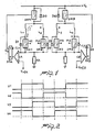
- This circuit comprises only one sense resistor R, and a single control loop, again comprising a flip-flop FF synchronized by a clock signal CLK and controlled by a comparator C which compares the voltage across the resistor R to a reference voltage V ref .
- the output signal Q of the flip-flop FF derives two AND gates, PA and PB, the outputs whereof control the switches SWA and SWB.
- the circuit comprises a first and a second flip-flop F1 and F2 of the toggle type, cascade connected.
- the flip-flop F1 is driven by the clock signal CLK, having twice the frequency with which the current in the motor is to be controlled, and with the reset input controlled by the output of the comparator C.
- the output Q1 of F1 controls the flip-flop F2, the outputs whereof Q2 and Q2 constitute the inputs for PA and PB.
- the reference voltage V ref assumes two different values V ref1 and V ref2 during the operation of the circuit, in relation to the two windings L1, L2 and L3, L4 of the motor, with the same period as the signals Q2, Q2 for the control of the gates PA and PB.
- This can be provided, for example, by using two analogic gates connected to the input of the comparator and controlled by the same signals Q2, Q2, not shown as they are obvious to the expert in the field.
- the first diagram illustrates the signal CLK with required timing.
- the signals Q2 and Q2 are then two square waves in opposite phase, with a period equal to twice that of CLK.
- the signal Q is constituted by pulses having a duration which depends on the switching threshold of the comparator C, but having the rising fronts occurring at the same frequency as CLK. If the reference voltages for the two loads are different, as illustrated in the last diagram, the voltage V sense across R, which starts every time from the same initial value with identical slope, causes the comparator C to trigger at different thresholds for the two loads, and this reflects in the different behaviour of the fluxes in the two windings.
- the gates PA and PB ensure that the two switches SWA and SWB never conduct simultaneously, and therefore the resistor R always measures only one of the currents.
- the currents in the two windings are thus defined in a fully independent manner.
- control signals of the second inputs of the gates PA and PB may be provided in another manner, according to a given clock signal, while remaining within the scope of the inventive concept.
Landscapes
- Engineering & Computer Science (AREA)
- Power Engineering (AREA)
- Control Of Stepping Motors (AREA)
Applications Claiming Priority (2)
| Application Number | Priority Date | Filing Date | Title |
|---|---|---|---|
| IT22141/87A IT1222824B (it) | 1987-10-05 | 1987-10-05 | Circuito di controllo di commutazione di corrente in carichi induttivi multipli,a singolo sensore di corrente,particolarmente per avvolgimenti di motori a passo |
| IT2214187 | 1987-10-05 |
Publications (3)
| Publication Number | Publication Date |
|---|---|
| EP0310858A2 true EP0310858A2 (fr) | 1989-04-12 |
| EP0310858A3 EP0310858A3 (en) | 1989-10-25 |
| EP0310858B1 EP0310858B1 (fr) | 1993-11-18 |
Family
ID=11192098
Family Applications (1)
| Application Number | Title | Priority Date | Filing Date |
|---|---|---|---|
| EP88115444A Expired - Lifetime EP0310858B1 (fr) | 1987-10-05 | 1988-09-21 | Circuit pour contrôler la commutation du courant dans des charges inductives multiples avec un seul capteur de courant, notamment pour des bobines de moteurs pas à pas |
Country Status (5)
| Country | Link |
|---|---|
| US (1) | US4928049A (fr) |
| EP (1) | EP0310858B1 (fr) |
| JP (1) | JP2619935B2 (fr) |
| DE (1) | DE3885699T2 (fr) |
| IT (1) | IT1222824B (fr) |
Cited By (4)
| Publication number | Priority date | Publication date | Assignee | Title |
|---|---|---|---|---|
| FR2692417A1 (fr) * | 1992-06-12 | 1993-12-17 | Sextant Avionique | Système de commande de moteur synchrone à rotor aimante. |
| WO1999019975A1 (fr) * | 1997-10-14 | 1999-04-22 | Maxim Integrated Products, Inc. | Circuit integre pour la commande de deux convertisseurs cc-cc imbriques |
| US6362608B1 (en) | 2001-02-01 | 2002-03-26 | Maxim Integrated Products, Inc. | Multi-phase switching converters and methods |
| WO2013000632A3 (fr) * | 2011-06-28 | 2013-05-23 | Robert Bosch Gmbh | Procédé et dispositif de mesure d'indications de courant de phase et d'une indication de courant d'excitation dans un moteur électrique à excitation électrique |
Families Citing this family (11)
| Publication number | Priority date | Publication date | Assignee | Title |
|---|---|---|---|---|
| US5221885A (en) * | 1991-05-03 | 1993-06-22 | Motorola, Inc. | Low-power dual voltage drive circuit and method |
| US5216345A (en) * | 1992-05-04 | 1993-06-01 | Hughes Aircraft Company | Mixed mode stepper motor controller and method |
| US5400239A (en) * | 1992-12-11 | 1995-03-21 | Northern Telecom Limited | Power converter with plural regulated outputs |
| DE19541832A1 (de) * | 1995-11-10 | 1997-05-15 | Thomson Brandt Gmbh | Motorsteuerung für elektronisch kommutierende Gleichstrommotoren zur Kompensation von Drehmomenteinbrüchen |
| US5990640A (en) * | 1996-03-29 | 1999-11-23 | Aim Controls, Inc. | Motor control apparatus |
| US5786681A (en) * | 1996-11-15 | 1998-07-28 | Dana Corporation | Active phase coil inductance sensing |
| US6107772A (en) * | 1997-09-26 | 2000-08-22 | Dana Corporation | Sensorless switched reluctance motor control |
| US5877608A (en) * | 1997-11-21 | 1999-03-02 | Philips Electronics North America Corporation | Current regulated multiphase motor driver with a common current sense element |
| DE19810469A1 (de) * | 1998-03-11 | 1999-09-16 | Philips Patentverwaltung | Schaltungsanordnung zur Kontrolle einer Ausgangslast |
| US6867566B2 (en) * | 2003-08-15 | 2005-03-15 | Ims Inc. | Method and apparatus for improved low current accuracy in multi-phase step motors |
| US7109742B2 (en) * | 2004-07-12 | 2006-09-19 | Motorola, Inc. | Current sensing in a two-phase motor |
Family Cites Families (9)
| Publication number | Priority date | Publication date | Assignee | Title |
|---|---|---|---|---|
| DE2258862A1 (de) * | 1972-12-01 | 1974-06-06 | Binder Magnete | Steuerschaltung zur schnellerregung elektromagnetischer systeme, insbesondere eines schrittmotors |
| FR2440642A1 (fr) * | 1978-11-02 | 1980-05-30 | Gilson Med Electr | Moteur pas a pas actionne par sous-multiple du pas |
| US4336484A (en) * | 1980-07-03 | 1982-06-22 | Textron, Inc. | Motor control |
| IT1134781B (it) * | 1980-12-18 | 1986-08-13 | Honeywell Inf Systems | Circuito di controllo per motore passo a passo |
| JPS58154398A (ja) * | 1982-03-08 | 1983-09-13 | Fuji Xerox Co Ltd | ステツプモ−タの励磁回路 |
| JPS60177696U (ja) * | 1984-04-27 | 1985-11-26 | 株式会社ピ−エフユ− | ステツピングモ−タ駆動回路装置 |
| US4574228A (en) * | 1984-12-07 | 1986-03-04 | International Business Machines Corp. | Current controlled motor drive circuit |
| JPS61266098A (ja) * | 1985-05-21 | 1986-11-25 | Tokyo Electric Co Ltd | パルスモ−タ制御装置 |
| US4792816A (en) * | 1986-09-22 | 1988-12-20 | Dr. Ing. Rudolf Hell Gmbh | Device for transporting photosensitive material past an imaging line in text and graphics image setting apparatus |
-
1987
- 1987-10-05 IT IT22141/87A patent/IT1222824B/it active
-
1988
- 1988-09-16 US US07/245,657 patent/US4928049A/en not_active Expired - Lifetime
- 1988-09-21 EP EP88115444A patent/EP0310858B1/fr not_active Expired - Lifetime
- 1988-09-21 DE DE3885699T patent/DE3885699T2/de not_active Expired - Fee Related
- 1988-10-04 JP JP63250737A patent/JP2619935B2/ja not_active Expired - Fee Related
Cited By (8)
| Publication number | Priority date | Publication date | Assignee | Title |
|---|---|---|---|---|
| FR2692417A1 (fr) * | 1992-06-12 | 1993-12-17 | Sextant Avionique | Système de commande de moteur synchrone à rotor aimante. |
| EP0574339A3 (fr) * | 1992-06-12 | 1994-01-12 | CROUZET Automatismes | Système de commande de moteur synchrone à rotor aimanté |
| WO1999019975A1 (fr) * | 1997-10-14 | 1999-04-22 | Maxim Integrated Products, Inc. | Circuit integre pour la commande de deux convertisseurs cc-cc imbriques |
| USRE38140E1 (en) | 1997-10-14 | 2003-06-10 | Maxim Integrated Products, Inc. | Dual interleaved DC to DC switching circuits realized in an integrated circuit |
| US6362608B1 (en) | 2001-02-01 | 2002-03-26 | Maxim Integrated Products, Inc. | Multi-phase switching converters and methods |
| WO2013000632A3 (fr) * | 2011-06-28 | 2013-05-23 | Robert Bosch Gmbh | Procédé et dispositif de mesure d'indications de courant de phase et d'une indication de courant d'excitation dans un moteur électrique à excitation électrique |
| CN103620943A (zh) * | 2011-06-28 | 2014-03-05 | 罗伯特·博世有限公司 | 在电激励的电机中测量相电流数据和激励电流数据的方法和装置 |
| CN103620943B (zh) * | 2011-06-28 | 2016-12-21 | 罗伯特·博世有限公司 | 在电激励的电机中测量相电流数据和激励电流数据的方法和装置 |
Also Published As
| Publication number | Publication date |
|---|---|
| EP0310858A3 (en) | 1989-10-25 |
| DE3885699D1 (de) | 1993-12-23 |
| US4928049A (en) | 1990-05-22 |
| JPH01117694A (ja) | 1989-05-10 |
| DE3885699T2 (de) | 1994-05-26 |
| IT8722141A0 (it) | 1987-10-05 |
| JP2619935B2 (ja) | 1997-06-11 |
| IT1222824B (it) | 1990-09-12 |
| EP0310858B1 (fr) | 1993-11-18 |
Similar Documents
| Publication | Publication Date | Title |
|---|---|---|
| EP0310858B1 (fr) | Circuit pour contrôler la commutation du courant dans des charges inductives multiples avec un seul capteur de courant, notamment pour des bobines de moteurs pas à pas | |
| US6400127B1 (en) | Dual mode pulse-width modulator for power control applications | |
| US6121760A (en) | Turn-on controller for switch-mode regulator | |
| US5617015A (en) | Multiple output regulator with time sequencing | |
| TWI842212B (zh) | 適用於可堆疊多相電源轉換器之控制電路與方法 | |
| CA2097547C (fr) | Dispositif et methode de repartition forcee des pertes de commutation par mosfet en parallele | |
| US5841261A (en) | System for controlling stepping motor for dividing a single step of the motor into plural sections and applying voltages whose levels are determined in accordance with the sections | |
| US5671115A (en) | Circuit arrangement for driving a contactor | |
| NL8301192A (nl) | Bekrachtigingsschakeling voor een borstelloze gelijkstroommotor. | |
| JPH0315295A (ja) | 二重モード制御式パルス幅変調器 | |
| EP2299579B1 (fr) | Extension de gamme de facteur d'utilisation réalisable dans un convertisseur progressif cc/cc avec une période de réinitialisation de verrouillage active | |
| EP0187224B1 (fr) | Commande de courant pour un circuit d'entraînement de moteur | |
| US4885673A (en) | Demagnetization monitoring device for a switching power supply with a primary and a secondary regulation | |
| EP0184659A1 (fr) | Appareil de multiplexage pour circuits commandés en phase | |
| EP0653833B1 (fr) | Moteur électrique sans balais et méthode pour commander le moteur | |
| US5999396A (en) | Circuit for driving a contactor | |
| CA1212152A (fr) | Circuit d'appareil de chauffage par induction a sources multiples d'energie haute frequence | |
| US4903188A (en) | Pulse width modulated inductive load controller | |
| US4158224A (en) | Inverter apparatus | |
| JPH06245586A (ja) | 双方向チョッパ・トランスコンダクタンス増幅器 | |
| US6414858B1 (en) | Multi-mode pulse-width modulator for power control applications | |
| US5317115A (en) | Electronic control for a microwave oven | |
| US12470145B2 (en) | Multiphase switching converter with stackable controllers | |
| GB2182814A (en) | Pulse shaping and delay circuit | |
| WO1993022833A1 (fr) | Generateur de rampe ameliore |
Legal Events
| Date | Code | Title | Description |
|---|---|---|---|
| PUAI | Public reference made under article 153(3) epc to a published international application that has entered the european phase |
Free format text: ORIGINAL CODE: 0009012 |
|
| AK | Designated contracting states |
Kind code of ref document: A2 Designated state(s): DE FR GB NL SE |
|
| PUAL | Search report despatched |
Free format text: ORIGINAL CODE: 0009013 |
|
| AK | Designated contracting states |
Kind code of ref document: A3 Designated state(s): DE FR GB NL SE |
|
| 17P | Request for examination filed |
Effective date: 19900310 |
|
| 17Q | First examination report despatched |
Effective date: 19920204 |
|
| GRAA | (expected) grant |
Free format text: ORIGINAL CODE: 0009210 |
|
| AK | Designated contracting states |
Kind code of ref document: B1 Designated state(s): DE FR GB NL SE |
|
| REF | Corresponds to: |
Ref document number: 3885699 Country of ref document: DE Date of ref document: 19931223 |
|
| ET | Fr: translation filed | ||
| PLBE | No opposition filed within time limit |
Free format text: ORIGINAL CODE: 0009261 |
|
| STAA | Information on the status of an ep patent application or granted ep patent |
Free format text: STATUS: NO OPPOSITION FILED WITHIN TIME LIMIT |
|
| 26N | No opposition filed | ||
| EAL | Se: european patent in force in sweden |
Ref document number: 88115444.7 |
|
| REG | Reference to a national code |
Ref country code: FR Ref legal event code: D6 |
|
| PGFP | Annual fee paid to national office [announced via postgrant information from national office to epo] |
Ref country code: SE Payment date: 20000906 Year of fee payment: 13 |
|
| PG25 | Lapsed in a contracting state [announced via postgrant information from national office to epo] |
Ref country code: SE Free format text: LAPSE BECAUSE OF NON-PAYMENT OF DUE FEES Effective date: 20010922 |
|
| REG | Reference to a national code |
Ref country code: GB Ref legal event code: IF02 |
|
| EUG | Se: european patent has lapsed |
Ref document number: 88115444.7 |
|
| PGFP | Annual fee paid to national office [announced via postgrant information from national office to epo] |
Ref country code: FR Payment date: 20020910 Year of fee payment: 15 |
|
| PGFP | Annual fee paid to national office [announced via postgrant information from national office to epo] |
Ref country code: GB Payment date: 20020918 Year of fee payment: 15 |
|
| PGFP | Annual fee paid to national office [announced via postgrant information from national office to epo] |
Ref country code: DE Payment date: 20020925 Year of fee payment: 15 |
|
| PGFP | Annual fee paid to national office [announced via postgrant information from national office to epo] |
Ref country code: NL Payment date: 20020930 Year of fee payment: 15 |
|
| PG25 | Lapsed in a contracting state [announced via postgrant information from national office to epo] |
Ref country code: GB Free format text: LAPSE BECAUSE OF NON-PAYMENT OF DUE FEES Effective date: 20030921 |
|
| PG25 | Lapsed in a contracting state [announced via postgrant information from national office to epo] |
Ref country code: NL Free format text: LAPSE BECAUSE OF NON-PAYMENT OF DUE FEES Effective date: 20040401 Ref country code: DE Free format text: LAPSE BECAUSE OF NON-PAYMENT OF DUE FEES Effective date: 20040401 |
|
| GBPC | Gb: european patent ceased through non-payment of renewal fee |
Effective date: 20030921 |
|
| PG25 | Lapsed in a contracting state [announced via postgrant information from national office to epo] |
Ref country code: FR Free format text: LAPSE BECAUSE OF NON-PAYMENT OF DUE FEES Effective date: 20040528 |
|
| NLV4 | Nl: lapsed or anulled due to non-payment of the annual fee |
Effective date: 20040401 |
|
| REG | Reference to a national code |
Ref country code: FR Ref legal event code: ST |