EP0310968A2 - Procédé et dispositif pour la cristallisation de granules synthétiques amorphes - Google Patents
Procédé et dispositif pour la cristallisation de granules synthétiques amorphes Download PDFInfo
- Publication number
- EP0310968A2 EP0310968A2 EP88116241A EP88116241A EP0310968A2 EP 0310968 A2 EP0310968 A2 EP 0310968A2 EP 88116241 A EP88116241 A EP 88116241A EP 88116241 A EP88116241 A EP 88116241A EP 0310968 A2 EP0310968 A2 EP 0310968A2
- Authority
- EP
- European Patent Office
- Prior art keywords
- heating gas
- granules
- funnel
- temperature
- stirring
- Prior art date
- Legal status (The legal status is an assumption and is not a legal conclusion. Google has not performed a legal analysis and makes no representation as to the accuracy of the status listed.)
- Granted
Links
- 238000000034 method Methods 0.000 title claims abstract description 19
- 229920000426 Microplastic Polymers 0.000 title description 3
- 239000008187 granular material Substances 0.000 claims abstract description 91
- 238000010438 heat treatment Methods 0.000 claims abstract description 62
- 238000002425 crystallisation Methods 0.000 claims abstract description 20
- 229920001871 amorphous plastic Polymers 0.000 claims abstract description 5
- 229920000728 polyester Polymers 0.000 claims abstract description 5
- 229920001169 thermoplastic Polymers 0.000 claims abstract description 4
- 239000004416 thermosoftening plastic Substances 0.000 claims abstract description 4
- 239000007789 gas Substances 0.000 claims description 58
- 238000003756 stirring Methods 0.000 claims description 51
- 238000002156 mixing Methods 0.000 claims description 21
- 230000008025 crystallization Effects 0.000 claims description 19
- 239000008188 pellet Substances 0.000 claims description 7
- 238000011049 filling Methods 0.000 claims description 6
- IJGRMHOSHXDMSA-UHFFFAOYSA-N Atomic nitrogen Chemical compound N#N IJGRMHOSHXDMSA-UHFFFAOYSA-N 0.000 claims description 4
- 230000001105 regulatory effect Effects 0.000 claims description 3
- 229920008790 Amorphous Polyethylene terephthalate Polymers 0.000 claims description 2
- 229910052757 nitrogen Inorganic materials 0.000 claims description 2
- 208000001848 dysentery Diseases 0.000 description 3
- 238000009413 insulation Methods 0.000 description 3
- -1 polyethylene terephthalate Polymers 0.000 description 3
- 229920000139 polyethylene terephthalate Polymers 0.000 description 3
- 239000005020 polyethylene terephthalate Substances 0.000 description 3
- 239000000523 sample Substances 0.000 description 3
- 230000001413 cellular effect Effects 0.000 description 2
- 238000013461 design Methods 0.000 description 2
- 238000011161 development Methods 0.000 description 2
- 238000012544 monitoring process Methods 0.000 description 2
- 238000012545 processing Methods 0.000 description 2
- 230000001276 controlling effect Effects 0.000 description 1
- 238000000605 extraction Methods 0.000 description 1
- 230000002349 favourable effect Effects 0.000 description 1
- 238000011068 loading method Methods 0.000 description 1
- NJPPVKZQTLUDBO-UHFFFAOYSA-N novaluron Chemical compound C1=C(Cl)C(OC(F)(F)C(OC(F)(F)F)F)=CC=C1NC(=O)NC(=O)C1=C(F)C=CC=C1F NJPPVKZQTLUDBO-UHFFFAOYSA-N 0.000 description 1
- 238000012546 transfer Methods 0.000 description 1
- 230000009466 transformation Effects 0.000 description 1
- 230000007704 transition Effects 0.000 description 1
Images

Classifications
-
- C—CHEMISTRY; METALLURGY
- C08—ORGANIC MACROMOLECULAR COMPOUNDS; THEIR PREPARATION OR CHEMICAL WORKING-UP; COMPOSITIONS BASED THEREON
- C08G—MACROMOLECULAR COMPOUNDS OBTAINED OTHERWISE THAN BY REACTIONS ONLY INVOLVING UNSATURATED CARBON-TO-CARBON BONDS
- C08G63/00—Macromolecular compounds obtained by reactions forming a carboxylic ester link in the main chain of the macromolecule
- C08G63/78—Preparation processes
- C08G63/80—Solid-state polycondensation
-
- B—PERFORMING OPERATIONS; TRANSPORTING
- B29—WORKING OF PLASTICS; WORKING OF SUBSTANCES IN A PLASTIC STATE IN GENERAL
- B29B—PREPARATION OR PRETREATMENT OF THE MATERIAL TO BE SHAPED; MAKING GRANULES OR PREFORMS; RECOVERY OF PLASTICS OR OTHER CONSTITUENTS OF WASTE MATERIAL CONTAINING PLASTICS
- B29B13/00—Conditioning or physical treatment of the material to be shaped
- B29B13/02—Conditioning or physical treatment of the material to be shaped by heating
- B29B13/021—Heat treatment of powders
-
- B—PERFORMING OPERATIONS; TRANSPORTING
- B29—WORKING OF PLASTICS; WORKING OF SUBSTANCES IN A PLASTIC STATE IN GENERAL
- B29B—PREPARATION OR PRETREATMENT OF THE MATERIAL TO BE SHAPED; MAKING GRANULES OR PREFORMS; RECOVERY OF PLASTICS OR OTHER CONSTITUENTS OF WASTE MATERIAL CONTAINING PLASTICS
- B29B9/00—Making granules
- B29B9/16—Auxiliary treatment of granules
- B29B2009/165—Crystallizing granules
-
- B—PERFORMING OPERATIONS; TRANSPORTING
- B29—WORKING OF PLASTICS; WORKING OF SUBSTANCES IN A PLASTIC STATE IN GENERAL
- B29K—INDEXING SCHEME ASSOCIATED WITH SUBCLASSES B29B, B29C OR B29D, RELATING TO MOULDING MATERIALS OR TO MATERIALS FOR MOULDS, REINFORCEMENTS, FILLERS OR PREFORMED PARTS, e.g. INSERTS
- B29K2067/00—Use of polyesters or derivatives thereof, as moulding material
Definitions
- the invention relates to a method for crystallizing at least the outer skin of grains of an amorphous plastic granulate, preferably thermoplastic polyester (PETP), whereby heating gas is fed to a stirring funnel and passed through the granules sinking through the stirring funnel in countercurrent, and wherein to monitor the crystallization the inlet temperature of the Mixing funnel introduced heating gas is detected.
- PETP thermoplastic polyester
- the invention further relates to a device suitable for carrying out the method.
- Plastic granules such as thermoplastic polyester (polyethylene terephthalate PETP), can be in amorphous or crystalline form. To transform the granules from amorphous to crystalline, the granules are heated by heating gas to the crystallization temperature, which is about 90 ° C to 110 ° C for the polyester mentioned.
- the crystallization temperature which is about 90 ° C to 110 ° C for the polyester mentioned.
- the granulate is filled into a stirring funnel equipped with an agitator, which it sinks through when the agitator rotates slowly.
- a heating gas such as air or nitrogen is blown into the mixing funnel in countercurrent to the sinking movement of the granulate from below.
- the heating gas the inlet temperature of which is set to just above the crystallization temperature, in the example mentioned to about 125 ° C., passes through the granules and heats them up to the crystallization temperature.
- the temperature of the heating gas leaving the stirring funnel through the heating gas outlet has hitherto been detected.
- this outlet temperature rose from the temperature of the freshly filled granulate, which is about room temperature, to the inlet temperature, it was certain that the crystallization of the Granules have taken place to the desired extent, so that crystallized granules could be removed from the stirring funnel.
- This also means that the crystallized granules are heated to the inlet temperature of the heating gas and are removed from the stirring funnel at this temperature.
- the residence time of a granulate filling in the mixing funnel is very long, it is usually two hours and more.
- the hourly amount of crystallized granules is correspondingly low.
- relatively high heat losses arise due to the high outlet temperature of the heating gas.
- a continuous removal of crystallized granules from the stirring funnel is hardly possible, because after each loading of the stirring funnel with amorphous and cold granules, it is necessary to wait until the outlet temperature has risen again to remove the grains.
- the invention is therefore based on the object of specifying a method for at least partially crystallizing amorphous plastic granules which, while reducing the heat losses which have occurred to date, allows the crystallized granules to be withdrawn continuously from the stirring funnel. Furthermore, a device is to be created which allows the method to be newly developed to be carried out.
- the inlet temperature of the heating gas introduced into the stirring funnel is kept at a value which is above the removal temperature of the granules from the stirring funnel. This makes it possible to control the removal of the crystallized granules from the stirred funnel in such a way that the removal temperature is just above the crystallization temperature but below the inlet temperature of the heating gas. It has been shown that it is sufficient for the desired crystallization, the granules in to heat a zone in the Ruhr funnel, which is axially much shorter, using hotter heating gas than before. Knowing the outlet temperature of the heating gas is therefore unnecessary for monitoring the crystallization.
- the invention reduces the heat losses because the heating gas can leave the stirring funnel with the temperature of the filled granulate, that is to say about room temperature.
- the heat carried by the entering heating gas is fully used for crystallization.
- the invention enables continuous operation of the mixing funnel, because the outlet temperature is no longer important. With the same size of hopper, the crystallization capacity, expressed as the granulate throughput per hour, increases very sharply.
- a particularly expedient embodiment of the invention provides that the inlet temperature is regulated as a function of the temperature of the granulate in the stirring funnel which is below the entry of the heating gas in the stirring funnel. This enables automatic operation of the mixing funnel.
- the invention can also be advantageously carried out in such a way that the rate of removal of the granules from the stirring funnel is regulated as a function of the temperature of the granules in the stirring funnel which are located below the inlet of the heating gas in the stirring funnel.
- the inlet temperature in a range from approximately 140 ° C. to approximately 180 ° C.
- the upper limit of the range, here 180 ° C. is preferably chosen so that it remains below the softening temperature of the granulate, which is about 250 ° C. for PETP. It is also advisable to blow the heating gas tangentially into a constricted ring area of the mixing funnel.
- a device with a stirring funnel which has an upper granule filling opening, a heating gas outlet, below the heating gas outlet has a pellet removal nozzle and an agitator inside, is particularly suitable when the method according to the invention is carried out if the agitator funnel for the passage of the granulate and the heating gas in the vicinity of the heating gas inlet has a narrow internal diameter.
- the flow cross-section created in this way which is relatively narrow in comparison to the cross section of the mixing funnel, leads to a relatively high air velocity in the constriction and to a very good heat transfer from the heating gas to the granulate.
- the short crystallization time of three to ten minutes which results from the invention is completely sufficient to partially or completely crystallize the plastic granules, depending on the type and grain size, or at least on the surface, such that the granules stick together during later storage or further processing can no longer occur.
- the area of the transformation from amorphous to crystalline is limited to a relatively small volume part of the mixing funnel, the mixing of the granules by the agitator can be restricted to this small area, so that the agitator can be designed more simply and requires less drive energy.
- a preferred embodiment of the device according to the invention provides that the stirring funnel has a circumferential wall inside and near the heating gas inlet, which extends obliquely inwards and downwards from the inner surface of the outer wall of the stirring funnel and a central passage opening as a narrowed ring area for the granules and forms the heating gas.
- the mentioned narrowing of the cross section of the mixing funnel can be realized in a structurally simple form.
- the flow cross-section for the granular crystallization can be made particularly favorable if, in a further development of the device according to the invention, a further circumferential wall is attached to the inside of the mixing funnel at a distance from the outer wall, which wall opens into the narrowed open space or into the passage opening , downward and inward inclined annulus extends downward and inward and encloses a core free of granules and heating gas.
- the further one is preferred Wall inclined noticeably flatter to the axis of the mixing funnel than the angle of repose of the granules to be crystallized. This inclination is advantageously less than that of the first wall.
- the further wall is the lower part of a double cone, which is fastened to a shaft that axially penetrates the mixing funnel with axially spaced stirring blades, the lower end of the double cone and thus the further wall is approximately at the level of the narrowed clear width.
- the double cone enclosing the core can then be inclined more towards the shaft in the upper part than its lower part.
- a first temperature sensor is to be emphasized, the probe of which is arranged in the granulate just below the narrow inside diameter of the mixing funnel.
- This temperature sensor shows the pellet temperature axially just below the crystallization zone, which can differ noticeably from the inlet temperature.
- This temperature sensor enables the inlet temperature to be controlled in such a way that excessive heating of the granules and thus the risk of undesired changes in the granules can be avoided.
- a second temperature sensor can advantageously be provided just above the granule extraction nozzle, which then enables safety monitoring so that only crystalline granules can be removed from the mixing funnel.
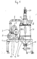
- the device shown in the drawing serves to crystallize at least the outer skin of granules of polyethylene terephthalate granules and comprises a stirring funnel 20, a blower 5 and a heater 7, which are mounted together with the air conduit connecting them on a frame 1 which can be moved here.
- Blower 5 and heater 7 are of conventional design, with the heater 7 also being noted that the heat which can be given off by the heating gas flowing through it can be controlled by a controller 100. It is only important for the invention that the heating gas outlet 24 of the stirring funnel 20 is connected to the suction opening of the blower 5 via an air line 2, that the compressed air outlet of the blower 5 via a further air line 3 to the inlet of the heater 7 and the outlet of the heater 7 is coupled to the heating gas inlet 26 of the stirring funnel 20 via a further air line 4. Immediately before the heating gas inlet 26, a third temperature sensor 14 is provided in the air line 4, the function of which will be explained below.
- the stirring funnel has a cylindrical body which tapers down to a pellet removal nozzle 28.
- an electric motor 23 is placed as a drive for a shaft 80 of an agitator, which axially passes through the body until just before the pellet removal nozzle 28.
- the body is composed of a cylindrical upper part 62, to the lower end of which a pedestal 70 is fastened, which has a cylindrical section 71 and a conical section 72 provided with the granulate removal nozzle 28.
- the cover 21 has an eccentric pellet filling opening 22 with a filling funnel 25 and the heating gas outlet 24 already mentioned.
- a plurality of arms 41, 43, 45, 47 which are equally spaced parallel to the source 80, project radially inward by about half the distance to the shaft 80, the profile of which is from above or laterally, the granules hitting from above at least not distracting down.
- stirrer arms 82, 84, 86, 88 are attached such that two axially adjacent stirrer arms as the shaft 80 rotates between two axially adjacent arms 41, 43 , 45, 47 drive through.
- the profile of the stirring arms ensures that when the granules 10 are stirred, no pressure acting on the granules in the sinking direction is exerted on them.
- a first conical wall 42 which extends inwards and downwards at an angle of 45 ° to the inner wall, is fastened to the inner wall of section 71 and leaves a circular passage opening 46 around shaft 80.
- the diameter of the passage opening 46 is approximately half the inner diameter of the section 71.
- the wall 42 is thickly thermally insulated by an insulation pad 49 which ends at the bottom transversely to the shaft 80.
- the air line 4 opens essentially tangentially to the inner wall through the heating gas inlet 26.
- a first pair of agitator arms with opposing agitator arms 92, 94 is attached to the shaft 80 such that the pair of agitator arms rotates in the passage opening 46 when the shaft 80 is rotating.
- Each agitator arm 92, 94 has a part 93, 95 protruding radially from the shaft 80, to which an end section 97, 99 running parallel to the conical wall 42 is connected.
- the shaft 80 also carries a double cone 55, the lower end of which lies just above the stirring arms 92, 94 and thus just above the passage opening 46.
- the double cone 55 is composed of a hood-shaped upper part 54 which widens conically downwards and a subsequent part 52 which tapers conically downwards. Both parts 52 and 54 are so far connected to each other and to the shaft 80 that neither granules nor significant heating gas can penetrate into the core 50 enclosed by the double cone. According to FIG. 2, the lower part 52 extends substantially beyond the space enclosed by the wall 42.
- annular space 40 is defined between the wall 42 and the further wall 52 of the lower double-cone part, which extends downwards and obliquely to the passage opening 46 and through which the granulate must flow.
- the slope of the wall 52 is steeper than the angle of repose of the granules to be crystallized in the annular space 40.
- the wall 52 consequently forms an angle of approximately 30 ° with the shaft 80.
- the upper part 54 of the double cone is inclined by approximately 45 ° against the shaft 80.
- Attached to the shaft 80 is a second pair of stirring arms with opposing stirring arms 32, 34 which project radially from the shaft 80, the radial parts 33, 35 of which close to the shaft penetrate the wall 52 and the free end parts 37, 39 angled parallel to the wall 42 with the upper one Edge of the wall 42 ends.
- the agitator arms 32, 34 are attached to the shaft 80 at a right angle to the agitator arms 92, 94. With the shaft 80 rotating, the stirring arms 32, 34 therefore pass through the upper section of the annular space 40.
- a holder 74 is provided for a first temperature sensor 18, the probe 19 of which is held just below the passage opening 46, approximately in the middle between the shaft 80 and the edge of the passage opening.
- a further holder 75 for a second temperature sensor 16 is provided on the section 72 above the pellet removal connection 28, the probe head being held approximately in the axial center of the section below the lower end of the shaft 80.
- the controller 100 contains a control circuit which compares the output signal from the first temperature sensor 18 as the actual signal of the temperature of the crystallized granulate with a stored setpoint of, for example, 120 ° C. and a control signal of the heater 7 resulting from the comparison for controlling the heat emitted by it feeds.
- the increase or decrease in the inlet temperature of the air resulting from the comparison is determined by controller 100 is monitored based on the output signal from third temperature sensor 14.
- the controller 100 influences the heater 7 in such a way that the inlet temperature of the air in the range between 140 ° C.
- PETP granules are introduced into the Ruhr funnel 20 through the filling opening 22 to a level indicated by a level indicator, not shown.
- the granules are usually at room temperature.
- the granules are added continuously so that the specified fill level is permanently maintained.
- Air is then blown into the stirring funnel 20 through the heating gas inlet at a temperature between approximately 140 ° C. and approximately 180 ° C., the temperature of which is maintained by the control in the specified range and is substantially higher than the crystallization temperature of approximately 90 ° C. to 110 ° ° C.
- the hot air flows under the insulation layer 49 radially inward around the edge of the passage opening into the granulate and up through it in the stirring funnel, which it leaves through the heating gas outlet 24.
- the controller 100 can cause the heater 7 to give off more heat to the air flowing through it, so that the inlet temperature moves in the direction of the upper limit value of approximately 180 ° C. what of the third temperature sensor 14 of the controller 100 is reported.
- the removal speed of the crystallized granules can be throttled by the nozzle 28. This is made possible, for example, by a controllable cellular wheel sluice connected to the connector 28, which allows the granulate removal speed to be controlled.
- the controller 100 throttles the heat output of the heater 7 into the air, or the removal speed of the crystallized granules is increased by the cellular wheel sluice until the reported temperature drops again to approximately 120 ° C. is.
- the second temperature sensor 16 serves as a check that the temperature of the granules leaving the stirring funnel 20 is actually 120 ° C. Since the second temperature sensor 16 lies below the hot air line in the stirring funnel, the temperature of the heating gas detected by it cannot be falsified.
Landscapes
- Mechanical Engineering (AREA)
- Engineering & Computer Science (AREA)
- Chemical & Material Sciences (AREA)
- Chemical Kinetics & Catalysis (AREA)
- Health & Medical Sciences (AREA)
- Thermal Sciences (AREA)
- Physics & Mathematics (AREA)
- Medicinal Chemistry (AREA)
- Polymers & Plastics (AREA)
- Organic Chemistry (AREA)
- Processing And Handling Of Plastics And Other Materials For Molding In General (AREA)
- Polyesters Or Polycarbonates (AREA)
- Other Resins Obtained By Reactions Not Involving Carbon-To-Carbon Unsaturated Bonds (AREA)
- Processes Of Treating Macromolecular Substances (AREA)
Applications Claiming Priority (2)
| Application Number | Priority Date | Filing Date | Title |
|---|---|---|---|
| DE19873733793 DE3733793A1 (de) | 1987-10-06 | 1987-10-06 | Verfahren und vorrichtung zum kristallisieren von amorphem kunststoffgranulat |
| DE3733793 | 1987-10-06 |
Publications (3)
| Publication Number | Publication Date |
|---|---|
| EP0310968A2 true EP0310968A2 (fr) | 1989-04-12 |
| EP0310968A3 EP0310968A3 (en) | 1990-01-10 |
| EP0310968B1 EP0310968B1 (fr) | 1993-02-24 |
Family
ID=6337738
Family Applications (1)
| Application Number | Title | Priority Date | Filing Date |
|---|---|---|---|
| EP88116241A Expired - Lifetime EP0310968B1 (fr) | 1987-10-06 | 1988-09-30 | Procédé et dispositif pour la cristallisation de granules synthétiques amorphes |
Country Status (3)
| Country | Link |
|---|---|
| EP (1) | EP0310968B1 (fr) |
| JP (1) | JP3025273B2 (fr) |
| DE (2) | DE3733793A1 (fr) |
Cited By (2)
| Publication number | Priority date | Publication date | Assignee | Title |
|---|---|---|---|---|
| WO2006087323A1 (fr) * | 2005-02-21 | 2006-08-24 | Mann+Hummel Protec Gmbh | Procede de cristallisation d'un granulat plastique amorphe |
| EP2043831B1 (fr) * | 2006-07-21 | 2013-02-27 | Bühler AG | Procédé de cristallisation d'un polymère cristallisant lentement et granulés polymères |
Families Citing this family (4)
| Publication number | Priority date | Publication date | Assignee | Title |
|---|---|---|---|---|
| DE4037443A1 (de) * | 1990-11-24 | 1992-05-27 | Mann & Hummel Filter | Vorrichtung zum trocknen von schuettgut |
| EP1753589A1 (fr) | 2004-05-26 | 2007-02-21 | Treofan Germany GmbH & Co.KG | Procede de cristallisation de granules en matieres plastiques amorphes |
| DE102006058642A1 (de) * | 2006-12-11 | 2008-06-12 | Bühler AG | Verfahren zur Herstellung homogen kristallisierter Polykondensatgranulate |
| KR102314044B1 (ko) | 2014-12-24 | 2021-10-19 | 삼성전자주식회사 | 공침 반응기 및 이를 이용한 이차 전지용 양극 활물질 전구체의 제조 방법 |
Family Cites Families (13)
| Publication number | Priority date | Publication date | Assignee | Title |
|---|---|---|---|---|
| GB1139224A (en) * | 1965-10-21 | 1969-01-08 | Ckd Praha | Heat exchange apparatus |
| DE1604390A1 (de) * | 1966-10-28 | 1970-09-17 | Voegele Ag J | Verfahren und Vorrichtung zum Vorwaermen von pulver- oder granulatfoermigen thermoplastischen Kunststoffen |
| US3547890A (en) * | 1967-08-23 | 1970-12-15 | Teijin Ltd | Process and apparatus for drying polyester particles |
| CH535928A (de) * | 1969-05-29 | 1973-04-15 | Schwarza Chemiefaser | Verfahren und Vorrichtung zum Trocknen von Granulaten aus synthetischen linearen Hoch-polymeren, insbesondere von Polyestergranulaten |
| JPS5125377A (ja) * | 1974-08-23 | 1976-03-01 | Morita Kuniko | Rentaihosoki |
| DE2558730C3 (de) * | 1975-12-24 | 1982-04-22 | Hoechst Ag, 6000 Frankfurt | Verfahren zum Kristallisieren und Trocknen von Polyethylenterephthalat und Vorrichtung zur Durchführung des Verfahrens |
| DE2642102C3 (de) * | 1976-09-18 | 1984-10-04 | Bühler-Miag GmbH, 3300 Braunschweig | Vorrichtung zum Kristallisieren von Kunststoffgranulat |
| JPS55154113A (en) * | 1979-05-22 | 1980-12-01 | Matsui Seisakusho:Kk | Drying and supplying method and device for amorphous granular body |
| US4276261A (en) * | 1979-07-16 | 1981-06-30 | The Goodyear Tire & Rubber Company | Polymerization apparatus and process |
| DD146489A1 (de) * | 1979-10-03 | 1981-02-11 | Reiner Pietag | Verfahren zur steuerung der trocknungsleistung von konvektionstrocknern |
| SU1022729A1 (ru) * | 1980-09-24 | 1983-06-15 | Проектно-конструкторское бюро по проектированию оборудования для производства пластических масс и синтетических смол | Аппарат дл обработки газом гранулированных полимеров |
| DD158528A1 (de) * | 1981-05-12 | 1983-01-19 | Peter Mueller | Vorrichtung zum foerdern,abmischen und trocknen von thermoplasten |
| DE3234598A1 (de) * | 1982-09-17 | 1984-03-22 | Brückner Trockentechnik GmbH & Co KG, 7250 Leonberg | Verfahren und vorrichtung zur regelung der verweilzeit einer warenbahn in einer waermebehandlungsvorrichtung |
-
1987
- 1987-10-06 DE DE19873733793 patent/DE3733793A1/de active Granted
-
1988
- 1988-09-30 DE DE8888116241T patent/DE3878625D1/de not_active Expired - Fee Related
- 1988-09-30 EP EP88116241A patent/EP0310968B1/fr not_active Expired - Lifetime
- 1988-10-06 JP JP63252860A patent/JP3025273B2/ja not_active Expired - Lifetime
Cited By (2)
| Publication number | Priority date | Publication date | Assignee | Title |
|---|---|---|---|---|
| WO2006087323A1 (fr) * | 2005-02-21 | 2006-08-24 | Mann+Hummel Protec Gmbh | Procede de cristallisation d'un granulat plastique amorphe |
| EP2043831B1 (fr) * | 2006-07-21 | 2013-02-27 | Bühler AG | Procédé de cristallisation d'un polymère cristallisant lentement et granulés polymères |
Also Published As
| Publication number | Publication date |
|---|---|
| JP3025273B2 (ja) | 2000-03-27 |
| DE3878625D1 (de) | 1993-04-01 |
| EP0310968B1 (fr) | 1993-02-24 |
| EP0310968A3 (en) | 1990-01-10 |
| JPH02643A (ja) | 1990-01-05 |
| DE3733793C2 (fr) | 1990-05-17 |
| DE3733793A1 (de) | 1989-04-20 |
Similar Documents
| Publication | Publication Date | Title |
|---|---|---|
| DE3207112C2 (de) | Trockner mit einer Misch- und Granuliereinrichtung | |
| EP2460581B1 (fr) | Procédé de mélange de matières en forme de poudre et/ou de granulés, et machine de mélange | |
| DE2642102C3 (de) | Vorrichtung zum Kristallisieren von Kunststoffgranulat | |
| EP0451546A2 (fr) | Tour de traitement d'un matériau pulvérulent ou granuleux, et procédé pour sa mise en oeuvre | |
| WO1991006364A1 (fr) | Dispositif pour l'agitation de particules solides | |
| EP1337321A1 (fr) | Reacteur en puits a cone de decharge gaze | |
| EP0310968B1 (fr) | Procédé et dispositif pour la cristallisation de granules synthétiques amorphes | |
| DE3617175C2 (de) | Einrichtung zum Passieren, insbesondere Granulieren und/oder Sieben eines Gutes | |
| EP3475479B1 (fr) | Dispositif de traitement de matériau comportant un récipient | |
| DE10204178A1 (de) | Verfahren und Vorrichtung zum Herstellen eines Einkristalls aus Halbleitermaterial | |
| DE69106421T2 (de) | Verfahren und Vorrichtung zur Herstellung von Metallpulver. | |
| DE3805118A1 (de) | Verfahren zum tiegelfreien zonenziehen von halbleiterstaeben und induktionsheizspule zu seiner durchfuehrung | |
| EP2388066A1 (fr) | Dispositif et procédé destinés à l'alimentation en houblon | |
| CH430397A (de) | Gravimetrische Ausgleichseinrichtung für Schüttgüter | |
| DE1778436B2 (de) | Verfahren und Vorrichtung zum kontinuierlichen Aufbereiten von pulverförmigen bis körnigen thermoplastischen Kunststoffen | |
| DE2364260A1 (de) | Waschzentrifuge | |
| DE60300291T2 (de) | Abgabevorrichtung für Substanzen zum landwirtschaftlichen Gebrauch | |
| DE102023108959A1 (de) | Mahleinheit für Getränkezubereitungsvorrichtung mit Mahlgradverstellung | |
| DE3840445C2 (de) | Vorrichtung und Verfahren zum Ziehen eines Einkristalls | |
| DE1253562B (de) | Prall- und Schaelmuehle mit mindestens zwei um eine lotrechte Achse umlaufenden Schleuderraedern | |
| DE69601164T2 (de) | Vorrichtung und verfahren zur herstellung eines extrudats | |
| WO2020207782A1 (fr) | Dispositif de fabrication de granulats ou de produits extrudés | |
| EP1270750B1 (fr) | Dispositif pour la préparation de matière sphérique en vrac | |
| CH632300A5 (en) | System for growing single crystals from a melt | |
| EP0258820B1 (fr) | Dispositif pour mélanger des matières granulaires dans un trémie |
Legal Events
| Date | Code | Title | Description |
|---|---|---|---|
| PUAI | Public reference made under article 153(3) epc to a published international application that has entered the european phase |
Free format text: ORIGINAL CODE: 0009012 |
|
| AK | Designated contracting states |
Kind code of ref document: A2 Designated state(s): DE FR GB IT |
|
| PUAL | Search report despatched |
Free format text: ORIGINAL CODE: 0009013 |
|
| AK | Designated contracting states |
Kind code of ref document: A3 Designated state(s): DE FR GB IT |
|
| 17P | Request for examination filed |
Effective date: 19900629 |
|
| 17Q | First examination report despatched |
Effective date: 19910613 |
|
| GRAA | (expected) grant |
Free format text: ORIGINAL CODE: 0009210 |
|
| AK | Designated contracting states |
Kind code of ref document: B1 Designated state(s): DE FR GB IT |
|
| REF | Corresponds to: |
Ref document number: 3878625 Country of ref document: DE Date of ref document: 19930401 |
|
| GBT | Gb: translation of ep patent filed (gb section 77(6)(a)/1977) |
Effective date: 19930309 |
|
| ITF | It: translation for a ep patent filed | ||
| ET | Fr: translation filed | ||
| PLBE | No opposition filed within time limit |
Free format text: ORIGINAL CODE: 0009261 |
|
| STAA | Information on the status of an ep patent application or granted ep patent |
Free format text: STATUS: NO OPPOSITION FILED WITHIN TIME LIMIT |
|
| 26N | No opposition filed | ||
| REG | Reference to a national code |
Ref country code: FR Ref legal event code: TP |
|
| ITPR | It: changes in ownership of a european patent |
Owner name: CESSIONE;SOMOS GMBH |
|
| REG | Reference to a national code |
Ref country code: GB Ref legal event code: 732E |
|
| PGFP | Annual fee paid to national office [announced via postgrant information from national office to epo] |
Ref country code: FR Payment date: 19980821 Year of fee payment: 11 |
|
| PG25 | Lapsed in a contracting state [announced via postgrant information from national office to epo] |
Ref country code: FR Free format text: LAPSE BECAUSE OF NON-PAYMENT OF DUE FEES Effective date: 20000531 |
|
| REG | Reference to a national code |
Ref country code: FR Ref legal event code: ST |
|
| REG | Reference to a national code |
Ref country code: GB Ref legal event code: IF02 |
|
| PGFP | Annual fee paid to national office [announced via postgrant information from national office to epo] |
Ref country code: DE Payment date: 20050912 Year of fee payment: 18 |
|
| PGFP | Annual fee paid to national office [announced via postgrant information from national office to epo] |
Ref country code: GB Payment date: 20050919 Year of fee payment: 18 |
|
| PG25 | Lapsed in a contracting state [announced via postgrant information from national office to epo] |
Ref country code: DE Free format text: LAPSE BECAUSE OF NON-PAYMENT OF DUE FEES Effective date: 20070403 |
|
| GBPC | Gb: european patent ceased through non-payment of renewal fee |
Effective date: 20060930 |
|
| PG25 | Lapsed in a contracting state [announced via postgrant information from national office to epo] |
Ref country code: GB Free format text: LAPSE BECAUSE OF NON-PAYMENT OF DUE FEES Effective date: 20060930 |
|
| PGFP | Annual fee paid to national office [announced via postgrant information from national office to epo] |
Ref country code: IT Payment date: 20070924 Year of fee payment: 20 |