EP0311112A2 - Dispositif de commande à distance - Google Patents
Dispositif de commande à distance Download PDFInfo
- Publication number
- EP0311112A2 EP0311112A2 EP88116675A EP88116675A EP0311112A2 EP 0311112 A2 EP0311112 A2 EP 0311112A2 EP 88116675 A EP88116675 A EP 88116675A EP 88116675 A EP88116675 A EP 88116675A EP 0311112 A2 EP0311112 A2 EP 0311112A2
- Authority
- EP
- European Patent Office
- Prior art keywords
- remote control
- timer
- receiver
- set forth
- transmitter
- Prior art date
- Legal status (The legal status is an assumption and is not a legal conclusion. Google has not performed a legal analysis and makes no representation as to the accuracy of the status listed.)
- Withdrawn
Links
Images


Classifications
-
- G—PHYSICS
- G07—CHECKING-DEVICES
- G07C—TIME OR ATTENDANCE REGISTERS; REGISTERING OR INDICATING THE WORKING OF MACHINES; GENERATING RANDOM NUMBERS; VOTING OR LOTTERY APPARATUS; ARRANGEMENTS, SYSTEMS OR APPARATUS FOR CHECKING NOT PROVIDED FOR ELSEWHERE
- G07C9/00—Individual registration on entry or exit
- G07C9/00174—Electronically operated locks; Circuits therefor; Nonmechanical keys therefor, e.g. passive or active electrical keys or other data carriers without mechanical keys
- G07C9/00182—Electronically operated locks; Circuits therefor; Nonmechanical keys therefor, e.g. passive or active electrical keys or other data carriers without mechanical keys operated with unidirectional data transmission between data carrier and locks
-
- G—PHYSICS
- G06—COMPUTING OR CALCULATING; COUNTING
- G06K—GRAPHICAL DATA READING; PRESENTATION OF DATA; RECORD CARRIERS; HANDLING RECORD CARRIERS
- G06K1/00—Methods or arrangements for marking the record carrier in digital fashion
- G06K1/12—Methods or arrangements for marking the record carrier in digital fashion otherwise than by punching
- G06K1/128—Methods or arrangements for marking the record carrier in digital fashion otherwise than by punching by electric registration, e.g. electrolytic, spark erosion
-
- G—PHYSICS
- G07—CHECKING-DEVICES
- G07C—TIME OR ATTENDANCE REGISTERS; REGISTERING OR INDICATING THE WORKING OF MACHINES; GENERATING RANDOM NUMBERS; VOTING OR LOTTERY APPARATUS; ARRANGEMENTS, SYSTEMS OR APPARATUS FOR CHECKING NOT PROVIDED FOR ELSEWHERE
- G07C9/00—Individual registration on entry or exit
- G07C9/00174—Electronically operated locks; Circuits therefor; Nonmechanical keys therefor, e.g. passive or active electrical keys or other data carriers without mechanical keys
- G07C9/00182—Electronically operated locks; Circuits therefor; Nonmechanical keys therefor, e.g. passive or active electrical keys or other data carriers without mechanical keys operated with unidirectional data transmission between data carrier and locks
- G07C2009/0023—Electronically operated locks; Circuits therefor; Nonmechanical keys therefor, e.g. passive or active electrical keys or other data carriers without mechanical keys operated with unidirectional data transmission between data carrier and locks with encription of the transmittted data signal
-
- G—PHYSICS
- G07—CHECKING-DEVICES
- G07C—TIME OR ATTENDANCE REGISTERS; REGISTERING OR INDICATING THE WORKING OF MACHINES; GENERATING RANDOM NUMBERS; VOTING OR LOTTERY APPARATUS; ARRANGEMENTS, SYSTEMS OR APPARATUS FOR CHECKING NOT PROVIDED FOR ELSEWHERE
- G07C9/00—Individual registration on entry or exit
- G07C9/00174—Electronically operated locks; Circuits therefor; Nonmechanical keys therefor, e.g. passive or active electrical keys or other data carriers without mechanical keys
- G07C9/00182—Electronically operated locks; Circuits therefor; Nonmechanical keys therefor, e.g. passive or active electrical keys or other data carriers without mechanical keys operated with unidirectional data transmission between data carrier and locks
- G07C2009/00238—Electronically operated locks; Circuits therefor; Nonmechanical keys therefor, e.g. passive or active electrical keys or other data carriers without mechanical keys operated with unidirectional data transmission between data carrier and locks the transmittted data signal containing a code which is changed
- G07C2009/00253—Electronically operated locks; Circuits therefor; Nonmechanical keys therefor, e.g. passive or active electrical keys or other data carriers without mechanical keys operated with unidirectional data transmission between data carrier and locks the transmittted data signal containing a code which is changed dynamically, e.g. variable code - rolling code
-
- G—PHYSICS
- G07—CHECKING-DEVICES
- G07C—TIME OR ATTENDANCE REGISTERS; REGISTERING OR INDICATING THE WORKING OF MACHINES; GENERATING RANDOM NUMBERS; VOTING OR LOTTERY APPARATUS; ARRANGEMENTS, SYSTEMS OR APPARATUS FOR CHECKING NOT PROVIDED FOR ELSEWHERE
- G07C9/00—Individual registration on entry or exit
- G07C9/00174—Electronically operated locks; Circuits therefor; Nonmechanical keys therefor, e.g. passive or active electrical keys or other data carriers without mechanical keys
- G07C2009/00753—Electronically operated locks; Circuits therefor; Nonmechanical keys therefor, e.g. passive or active electrical keys or other data carriers without mechanical keys operated by active electrical keys
- G07C2009/00769—Electronically operated locks; Circuits therefor; Nonmechanical keys therefor, e.g. passive or active electrical keys or other data carriers without mechanical keys operated by active electrical keys with data transmission performed by wireless means
- G07C2009/00785—Electronically operated locks; Circuits therefor; Nonmechanical keys therefor, e.g. passive or active electrical keys or other data carriers without mechanical keys operated by active electrical keys with data transmission performed by wireless means by light
-
- G—PHYSICS
- G07—CHECKING-DEVICES
- G07C—TIME OR ATTENDANCE REGISTERS; REGISTERING OR INDICATING THE WORKING OF MACHINES; GENERATING RANDOM NUMBERS; VOTING OR LOTTERY APPARATUS; ARRANGEMENTS, SYSTEMS OR APPARATUS FOR CHECKING NOT PROVIDED FOR ELSEWHERE
- G07C2209/00—Indexing scheme relating to groups G07C9/00 - G07C9/38
- G07C2209/06—Involving synchronization or resynchronization between transmitter and receiver; reordering of codes
Definitions
- the present invention relates to a remote control transmitting/receiving system suited to electric and electronic appliances and electronic locks or the like and, more particularly, to the protection of privacy and security in such a system.
- a conventional control system for controlling a remote control device will be described by exemplifying a remote control key and lock.
- a code Sa from a code setting unit 52 is converted into serial data Sb by means of a signal generating unit 53.
- remote control transmitting data Sc is transmitted by a transmitting unit 55 with infrared rays serving as a signal carrier medium.
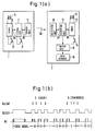
- a guide signal having a constant pulse width for picking up the head is followed by a setting code Sa of "0101" in this example.
- the guide signal and the setting code Sa are PPM-modulated at a carrier frequency of 38 kHz, thus forming a remote control signal Sc which will be transmitted as an infrared ray of light.
- the infrared remote control signal is received by a receiving unit 56 of a remote control receiver (remote control lock device) 51 and is converted into serial data Sd.
- the thus converted serial data Sd is decrypted by a signal decryption unit 57.
- a lock member 60 is opened and closed by a driver member 59. If not, no opening and closing operation is performed.
- the code Sa, Se is previously set in the code setting units 52 and 58 of the remote control transmitter and receiver. The code differs depending on the respective remote control locks, whereby security is maintained.
- a first embodiment of a remote control transmitting/receiving system according to the present invention will hereinafter be described by exemplifying remote control key and lock devices with reference to FIGS. 1(a) to 1(c).
- a remote control transmitter (remote control key device in this example) generally designated at 1 includes a timer unit 5 having a crystal vibrator 4 and a reset switch 6. On turning ON the reset switch 6, the measurement of time is initiated.
- a signal generating unit 7 reads timer data Da of the timer unit 5. Subsequently the timer data Da is converted into serial data Db and is then transmitted to a transmitting unit 9.
- the transmitting unit 9 serves to modulate a carrier frequency of 38 kHz with the serial data Db, and an infrared-ray signal is transmitted as transmission data Dc.
- a remote control receiver (remote control lock device in this example) generally indicated at 2 comprises a timer unit 13 including a crystal vibrator 12 having the same frequency as the crystal vibrator 4 of the remote control transmitter 1, and a reset switch 14.
- a timer unit 13 including a crystal vibrator 12 having the same frequency as the crystal vibrator 4 of the remote control transmitter 1, and a reset switch 14.
- a receiving unit 10 receives the infrared signal Dc which will then be converted into serial data Dd (its waveform is the same as that of the data Dc).
- a signal decryption unit 11 decodes the serial data Dd and judges whether the received data coincides with the timer data De on the receiving side or not. If the received data coincides with the timer data De, an ON/OFF signal is outputted, and a lock member 16 is opened and closed by a driver unit 15.
- the timer units 5 and 13 on the transmitting side and on the receiving side, respectively, have a slight time difference because of a natural frequency difference of the crystal vibrators, an oscillating circuit difference, a temperature difference and/or a reset timing difference. If the received data Dd does not exactly coincide with the timer data De on the receiving side, preferably the following processes are effected.
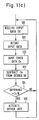
- the signal decryption unit 11 composed of a microcomputer deals with the timer data of tens digit of minutes at the maximum.
- the difference between the received data and the receiver's timer data is obtained in a step 123 in accordance with the flowchart of FIG. 1(c). If the difference falls within a range of 20 minutes in step 124, it is determined that the received data coincides with the timer data.
- the operation of the remote control lock depends on the coincidence of transmitted information with the receiver's timer information.
- the timer data used in this example includes the digits for hour and minute. However, if such units as year, month, day and time are employed, the amount of information increases. The number of remote control lock devices with the same hour of their timer data decreases in terms of probability, thereby improving the security. In this example, concerning the normal accuracy of a quartz chronometer, a monthly time-difference is approximately ⁇ 30 sec.
- the reference value for judging the coincidence of the timer information is approximately ⁇ 20 minutes. If a period for use of the remote control lock is to be extended, the above-mentioned reference value may be increased, or alternatively the time precision of the timer unit may be improved.
- the timer information has been explained on the basis of ordinarily used time units as hour and minute in this example.
- the information of the remote control transmitting unit must be identical with that of the remote control receiving unit with a slight difference, so that the frequency of the crystal vibrator may have any value, i.e. the time unit is not necessarily based on hour, minute and second.
- timer information is converted directly into an infrared signal.
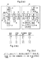
- timer data converting units 22 and 29 serve to read the timer data of timer units 20 and 31 to read a cipher code in referring to cipher tables 21 and 30, and to cipher the timer data in accordance with the cipher code.
- the thus ciphered data is transmitted via a signal generating unit 24, a transmitting unit 25 and a receiving unit 26 to a signal decryption unit 27.
- a way of determination may be based on an arbitrary table depicted in FIG. 2(b) or a cipher table determined by gene rating random numbers.
- the timer information is thus ciphered
- the ciphered information can by no means be decrypted by analyzing the infrared signal.
- the security can be further ensured.
- code setting units 23 and 28 are added, and the timer information and the codes to be set are, as illustrated in the waveform diagram of FIG. 2(c), arranged in series and form the infrared signal.
- This code setting device may be of a fixed system or a system in which the user is allowed to arbitrarily set the code.
- the code setting unit 23 of the remote control transmitter 32 serves as a ten-key.
- the password numbers are so inputted from the ten-key as to become codes of the above described code setting unit.
- the timer information is ciphered, but the codes of the code setting unit may also be ciphered.
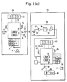
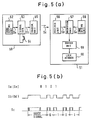
- FIG. 3(a) corresponds to the block diagram of FIG. 2(a).
- the transmitting circuit is incorporated into a wrist watch in common with a clock circuit, while the receiving circuit is incorporated into an electric lock case.
- the component that will first be described is the wrist watch 69 forming the transmitter.
- the timer unit 20, the cipher table 21, the timer data converting unit 22 and the signal generating unit 24 which are all shown in FIG. 2(a) are built in a microcomputer 73.
- a code setting unit 23 depicted in FIG. 2(a) consists of a keyboard 75 and a RAM 76 of the microcomputer 73.
- the transmitting unit 25 depicted in FIG. 2(a) is composed of a 456 kHz ceramic vibrator 74, the microcomputer 73, a transistor 78 and an infrared light emitting diode (LED) 79.
- a 32.768 kHz crystal vibrator 71 connected to the microcomputer 73 is oscillated and frequency-divided by an oscillation circuit and a frequency dividing circuit, respectively, which are built in the microcomputer 73, thereby generating one-second signals and ten-second signals which will be counted in the RAM 76.
- a clock counter 101 and a transmitting counter 103 are made to function as a timer unit.
- the clock counter 101 is composed of an hour-minute-second counter for counting the one-second signals; and, as illustrated in FIG. 3(b), the data thereof are, though there is no correspondence in the preceding embodiment, displayed on an LCD display unit 72 serving as a timer data display unit provided on the upper surface of the wrist watch 69.
- the transmitting counter 103 consisting of a 20-bit binary counter for counting the ten-second signals is employed as a timer device for signal transmission.
- the wrist watch 69 actuates the microcomputer 73 by clocks of 32.768 kHz in order to reduce the consumption of electric power.
- code setting In the case of code setting, hour modification and signal transmission, high-speed processing is executed by starting a 456 kHz ceramic vibrator.
- the code setting is performed in the following manner in accordance with a program which will be executed only once immediately after, for instance, a lithium battery (not illustrated) has been inputted as a power source.
- random 20-bit data is automatically stored as an initial value in the transmitting counter 103.
- three keys among keys 0 to 9 of the keyboard 75 are pressed, and the inputted 3-digit (12 bits) data is stored in a fixed code memory 105 depicted in FIG. 3(d).
- the transmitting counter 103 initiates a binary-base time measurement by employing the ten-second signals, with the initial value stored in the transmitting counter 103 serving as an origin.
- the data in fixed code memory 105 continues to be used as a fixed number of the wrist watch 69 till the lithium battery is inputted once again.
- the password code memory 107 is a memory intended to transmit the password numbers inputted from the keyboard every time the transmission is executed.
- the data are ciphered on the basis of the cipher table stored in ROM 77, the order of data sets is changed and is stored in the transmitting memory 109. Then, a carrier frequency of 38 kHz obtained by dividing the frequency of 456 kHz of the ceramic vibrator 74 by a factor of 12, is modulated by the data and the thus modulated data signal is transmitted by means of the infrared light emitting diode 79.
- the microcomputer 83 depicted in FIG. 3(a) incorporates a timer unit 31, a cipher table 30, a timer data converting unit 29, a signal decryption unit 27 and a code setting unit 28 which are shown in FIG. 2(a).
- the receiving unit 26 shown in FIG. 2(a) is a light receiving unit 80 consisting of a photodiode 92, an amplifier 93, a band pass filter 94 and an integrator 95 which are illustrated in FIG. 3(a).
- the driver unit 36 of FIG. 2(a) corresponds to a transistor 88 of FIG. 3(a), while the lock member 37 of FIG.
- the microcomputer 83 to which a 32.768 kHz crystal vibrator 81 is, as in the case of the microcomputer 73 of the wrist watch 69, connected generates one-second signals and ten-second signals; and a clock counter 102 and a receiving counter 104, which are shown in FIG. 3(d), are formed as part of a RAM 86.
- the clock counter 102 is composed of an hour-minute-second counter for counting the one-second signals; and the data thereof are, as illustrated in FIG. 3(c), displayed on an LCD display unit 82 from a side surface of an electric lock 70.
- the receiving counter 104 consisting of a 20-bit binary counter for counting the ten-second signals is used as a timer device for comparison with the received timer data.
- the electric lock 70 whose power source is a dry element battery (not shown) is arranged to be used by operating the microcomputer 83 with clocks of 32.768 kHz for the purpose of diminishing the consumption of electric power.
- a high-speed processing is effected by starting the 456 kHz ceramic vibrator 84 at the time of code setting, hour modification and receiving process.
- the code setting with respect to the electric lock 70 involves the steps of first pushing a function key C′ of the keyboard 85; secondly transferring the data by pushing a function key C of the wrist watch keyboard while directing the infrared light emitting diode 79 of the code-registered wrist watch 69 to a light receiving unit 80; and finally inputting the transferred data to the RAM 86 of the microcomputer 83.
- the data of the transmitting memory 109 are transmitted in the form of waveforms depicted in FIG. 2(c) in the second embodiment and are received by the light receiving unit 80. The thus received data are stored in a receiving memory 110 of FIG. 3(d).
- the data of the receiving memory 110 are deciphered in accordance with the cipher table of the ROM 87.
- the order of data sets is rearranged; the data of the transmitting counter 103 are stored in the receiving counter 104; the data of the fixed code memory 105 are stored in the fixed code memory 106; and the data of the password code memory 107 are stored in the password code memory 108.
- the receiving counter 104 (20 bits) initiates the binary-base time measurement by employing the ten-second signals. This setting results in a 44-bit ID code including 20-bit timer information together with a total of 6-digit 24-bit information of the fixed code memory 106 and the password code memory 108.
- the timer information of the electric lock 70 is equalized to the timer information of the wrist watch 69.
- the same effects can be exhibited as in the initial value setting method in which the timer information of the receiver 33 is equalized to the timer information of the transmitter 32 by simultaneously turning ON the reset switches 34 and 38 of FIG. 2(a) in the foregoing second embodiment.
- FIG. 3(d) it is possible to register the ID codes of n wrist watches by having n ID codes (a set of receiving counter, fixed code memory and password code me mory), whereby a number of n specified users is permitted to use them.
- the code setting with respect to the electric lock 70 is practicable by inputting of other password numbers of, e.g., 4 digits, than the previous password code.
- This mechanism is capable of prohibiting illegal code setting of any third party who does not know the 4-digit password code.
- the code setting of the wrist watch 69 and the electric lock 70 is thus completed.
- This infrared light emitting diode is provided inwardly of the wrist watch 69 and has to be directed to the light receiving unit 80 disposed on the surface of the electric lock 70 depicted in FIG. 3(c).
- the data of the transmitting memory 109, when received by the light receiving unit 80 are stored in the receiving memory 110.
- the thus stored data are then deciphered on the basis of a cipher table of ROM 87, and the order of data sets is rearranged. Then a comparative judgement is made as to whether or not the data coincide with any one of previously registered ID codes 1 to n. If the data coincide therewith, transistor 88 is turned ON, and lock rod 90 is moved by driving electromagnetic solenoid 89, thus executing locking and unlocking processes.
- the LCD display units 72 and 82 do not only serve to simply indicate the present hour to the user but also serve as outputting means of timer information of the respective timer unit.
- the LCD display units 72 and 82 perform a function to keep the transmitting counter 103 and the receiving counter 104 so as to have the same timer information. More specifically, if a difference between those pieces of timer information is produced due to an inaccuracy of a crystal vibrator or variations in temperature, the difference also appears on the LCD display units 72 and 82 indicating the present hour. If such difference is realized it will be feasible to modify the hour by using function keys A, B, A′ and B′ of the keyboards 75 and 85.
- the same amount of hour-modification is simultaneously effected on the transmitting counter 103 and receiving counters 104 as well as on the display clock counters 101 and 102, thereby constantly providing the identical timer information.
- the display unit 72 is corrected by the function keys A and B and the display unit 82 is corrected by the function keys A′ and B′.
- the electric lock 70 equipped with a buzzer 91 as an alarm device gives an alarm to inform the user of the necessity for modifying the hour, if a timer difference between the timer information of the transmitting counter 103 and that of the receiving counter 104 is, e.g., 3 minutes or more.
- the predetermined reference time value described in the first embodiment can be reduced to, e.g., approximately 5 minutes.
- the time for which a copy remote controller can be used illegally is reduced to several minutes, thereby improving the security.
- the reference time value is set to 5 minutes
- 5 bits of 20 bits of the transmitting counter 103 are within 5 minutes, and the remaining 15 bits are permitted to be used as an ID code.
- the remote control transmitter may be incorporated in, e.g., a card key holder, pendant or the like, while the remote control receiver may be embedded into a door, attached to a wall or incorporated in an interphone.
- the remote control transmitter may be incorporated in, e.g., a card key holder, pendant or the like, while the remote control receiver may be embedded into a door, attached to a wall or incorporated in an interphone.
- the foregoing description mentions the use of a 32,768 kHz crystal vibrator for measuring the time and a 456 kHz ceramic vibrator for the microcomputer clock in combination with the remote control transmitter and receiver.
- the 32,768 kHz crystal vibrator may function as clocks of the microcomputers 73 and 83, resulting in less consumption of electric power.
- remote control key and lock devices are explained.
- the control code is added in series to the ID code including the timer information and the code of the code setting device.
- the timer information and the code of the code setting device are provided in the transmitter and coincide with those which are provided in receiver control can be effected.
- the present invention exhibits the effectiveness in a case where a switch that a third party is prohibited from using is replaced by the remote control device in home electric products like TV sets, VTRs or the like, electronic appliances such as computers, word processors or the like and machineries or measuring instruments provided in factories. Besides, the present invention provides effects in the remote control transmitting/receiving system that should absolutely not be copied by others. Where the control code depicted in FIG.
- infrared light is employed as a signal medium.
- the signal medium may, however, involve the use of visible light, an acoustic wave, an electromagnetic wave, a voltage, an electric current and so forth. Any kind of signal medium can likewise provide the explained effects.
Landscapes
- Engineering & Computer Science (AREA)
- Physics & Mathematics (AREA)
- General Physics & Mathematics (AREA)
- Computer Networks & Wireless Communication (AREA)
- Theoretical Computer Science (AREA)
- Selective Calling Equipment (AREA)
- Lock And Its Accessories (AREA)
Applications Claiming Priority (4)
| Application Number | Priority Date | Filing Date | Title |
|---|---|---|---|
| JP25302287 | 1987-10-07 | ||
| JP253022/87 | 1987-10-07 | ||
| JP165269/88 | 1988-07-01 | ||
| JP63165269A JP2767816B2 (ja) | 1987-10-07 | 1988-07-01 | リモコン送信・受信装置 |
Publications (2)
| Publication Number | Publication Date |
|---|---|
| EP0311112A2 true EP0311112A2 (fr) | 1989-04-12 |
| EP0311112A3 EP0311112A3 (fr) | 1989-11-23 |
Family
ID=26490069
Family Applications (1)
| Application Number | Title | Priority Date | Filing Date |
|---|---|---|---|
| EP88116675A Withdrawn EP0311112A3 (fr) | 1987-10-07 | 1988-10-07 | Dispositif de commande à distance |
Country Status (2)
| Country | Link |
|---|---|
| EP (1) | EP0311112A3 (fr) |
| JP (1) | JP2767816B2 (fr) |
Cited By (38)
| Publication number | Priority date | Publication date | Assignee | Title |
|---|---|---|---|---|
| FR2652216A1 (fr) * | 1989-09-20 | 1991-03-22 | Rockwell Cim | Procede et dispositif de generation et de validation d'un message numerique et application d'un tel dispositif. |
| WO1991006926A1 (fr) * | 1989-10-31 | 1991-05-16 | Security Dynamics Technologies, Inc. | Methode et dispositif destines a assurer la securite de l'identification et de la verification |
| WO1991016517A1 (fr) * | 1990-04-25 | 1991-10-31 | Skidata Computer Gesellschaft M.B.H. | Serrure de porte |
| FR2678755A1 (fr) * | 1991-06-07 | 1993-01-08 | Trw Sipea Spa | Telecommande a securite optimisee. |
| EP0533507A1 (fr) * | 1991-09-20 | 1993-03-24 | Mas-Hamilton Group | Serrure électronique à pène à sécurité renforcée |
| EP0559930A1 (fr) * | 1992-03-10 | 1993-09-15 | Siemens Aktiengesellschaft | Procédé pour l'alimentation en courant électrique du récepteur d'un système de verrouillage d'un véhicule à moteur |
| EP0570761A1 (fr) * | 1992-05-18 | 1993-11-24 | Lectron Products, Inc. | Système passif d'entrée sans clef |
| DE9419635U1 (de) * | 1994-12-09 | 1995-03-02 | Engel, Gerhard, Dipl.-Ing., 41564 Kaarst | Sicherungseinrichtung insbesondere für Kraftfahrzeuge |
| AT155U1 (de) * | 1991-01-22 | 1995-03-27 | Skidata Gmbh | Einrichtung zur berechtigung der bedienung eines geraetes mit einer betaeätigungseinheit |
| EP0698706A1 (fr) * | 1994-08-26 | 1996-02-28 | TEMIC TELEFUNKEN microelectronic GmbH | Procédé d'exploitation d'un système de fermeture pour objets verrouillables |
| US5517187A (en) * | 1990-05-29 | 1996-05-14 | Nanoteq (Pty) Limited | Microchips and remote control devices comprising same |
| AT871U1 (de) * | 1995-04-19 | 1996-06-25 | Skidata Gmbh | Datenträger |
| US5612683A (en) * | 1994-08-26 | 1997-03-18 | Trempala; Dohn J. | Security key holder |
| US5623257A (en) * | 1992-03-10 | 1997-04-22 | Bachhuber; Anton | Method and apparatus for supplying power to the receiver of a motor vehicle locking system |
| US5686904A (en) * | 1991-05-29 | 1997-11-11 | Microchip Technology Incorporated | Secure self learning system |
| US6049289A (en) * | 1996-09-06 | 2000-04-11 | Overhead Door Corporation | Remote controlled garage door opening system |
| EP0775918A3 (fr) * | 1995-11-22 | 2000-06-28 | Kabushiki Kaisha Tokai-Rika-Denki-Seisakusho | Système de transmission et réception |
| US6108326A (en) * | 1997-05-08 | 2000-08-22 | Microchip Technology Incorporated | Microchips and remote control devices comprising same |
| US6130621A (en) * | 1992-07-09 | 2000-10-10 | Rsa Security Inc. | Method and apparatus for inhibiting unauthorized access to or utilization of a protected device |
| EP0911466A3 (fr) * | 1997-10-16 | 2000-10-18 | feig electronic Gesellschaft mit beschränkter Haftung | Dispositif électronique programmable de fermeture sans usure |
| US6154544A (en) | 1995-05-17 | 2000-11-28 | The Chamberlain Group, Inc. | Rolling code security system |
| US6166650A (en) * | 1991-05-29 | 2000-12-26 | Microchip Technology, Inc. | Secure self learning system |
| US6191701B1 (en) * | 1995-08-25 | 2001-02-20 | Microchip Technology Incorporated | Secure self learning system |
| DE10004866A1 (de) * | 2000-02-04 | 2001-08-09 | S. Siedle & Soehne,Telefon- Und Telegrafenwerke Stiftung & Co | Türanlage |
| FR2823167A1 (fr) * | 2001-03-30 | 2002-10-11 | Siemens Ag | Dispositif pour commander un dispositif de securite |
| US6980655B2 (en) | 2000-01-21 | 2005-12-27 | The Chamberlain Group, Inc. | Rolling code security system |
| US7412056B2 (en) | 1995-05-17 | 2008-08-12 | The Chamberlain Group, Inc. | Rolling code security system |
| GB2451315A (en) * | 2007-07-25 | 2009-01-28 | Ford Global Tech Llc | A portable control device |
| US7492905B2 (en) | 1995-05-17 | 2009-02-17 | The Chamberlain Group, Inc. | Rolling code security system |
| US7529939B2 (en) | 2000-12-19 | 2009-05-05 | Azoteq Pty Ltd. | Method of and apparatus for transferring data |
| US7594021B2 (en) | 2003-04-11 | 2009-09-22 | Sony Corporation | Radio communication system, radio communication apparatus and method, and program |
| US10652743B2 (en) | 2017-12-21 | 2020-05-12 | The Chamberlain Group, Inc. | Security system for a moveable barrier operator |
| US10862924B2 (en) | 2005-06-30 | 2020-12-08 | The Chamberlain Group, Inc. | Method and apparatus to facilitate message transmission and reception using different transmission characteristics |
| US10944559B2 (en) | 2005-01-27 | 2021-03-09 | The Chamberlain Group, Inc. | Transmission of data including conversion of ternary data to binary data |
| US10997810B2 (en) | 2019-05-16 | 2021-05-04 | The Chamberlain Group, Inc. | In-vehicle transmitter training |
| US11074773B1 (en) | 2018-06-27 | 2021-07-27 | The Chamberlain Group, Inc. | Network-based control of movable barrier operators for autonomous vehicles |
| US11423717B2 (en) | 2018-08-01 | 2022-08-23 | The Chamberlain Group Llc | Movable barrier operator and transmitter pairing over a network |
| US12149618B2 (en) | 2005-01-27 | 2024-11-19 | The Chamberlain Group Llc | Method and apparatus to facilitate transmission of an encrypted rolling code |
Families Citing this family (8)
| Publication number | Priority date | Publication date | Assignee | Title |
|---|---|---|---|---|
| JPH02288592A (ja) * | 1989-04-28 | 1990-11-28 | Alpha Corp | 送信装置 |
| JP2768975B2 (ja) * | 1989-04-28 | 1998-06-25 | 株式会社アルファ | 遠隔操作装置 |
| US6175312B1 (en) | 1990-05-29 | 2001-01-16 | Microchip Technology Incorporated | Encoder and decoder microchips and remote control devices for secure unidirectional communication |
| JP4223698B2 (ja) * | 2001-06-18 | 2009-02-12 | ソニー株式会社 | 情報処理装置および方法、情報処理システム、記録媒体、並びにプログラム |
| JP2003256977A (ja) * | 2002-03-05 | 2003-09-12 | Yokogawa Electric Corp | リモコン対応形測定装置 |
| JP4329388B2 (ja) | 2003-04-22 | 2009-09-09 | ソニー株式会社 | データ通信システム、データ通信装置及びデータ通信方法、並びにコンピュータ・プログラム |
| JP4995219B2 (ja) * | 2009-03-30 | 2012-08-08 | 京楽産業.株式会社 | 電子機器、主制御基板、周辺基板、認証方法および認証プログラム |
| JP4995220B2 (ja) * | 2009-03-30 | 2012-08-08 | 京楽産業.株式会社 | 電子機器、主制御基板、周辺基板、認証方法および認証プログラム |
Family Cites Families (3)
| Publication number | Priority date | Publication date | Assignee | Title |
|---|---|---|---|---|
| SE381940B (sv) * | 1972-04-11 | 1975-12-22 | Gretag Ag | Anordning for enskild identifiering av ett flertal individer |
| US4320387A (en) * | 1978-12-28 | 1982-03-16 | Powell William S | Information communicating apparatus and method |
| FR2607544A1 (fr) * | 1986-11-27 | 1988-06-03 | Neiman Sa | Serrure electronique a changement de code periodique |
-
1988
- 1988-07-01 JP JP63165269A patent/JP2767816B2/ja not_active Expired - Lifetime
- 1988-10-07 EP EP88116675A patent/EP0311112A3/fr not_active Withdrawn
Cited By (55)
| Publication number | Priority date | Publication date | Assignee | Title |
|---|---|---|---|---|
| EP0419306A1 (fr) * | 1989-09-20 | 1991-03-27 | ROCKWELL BODY AND CHASSIS SYSTEMS - FRANCE, en abrégé: ROCKWELL BCS - FRANCE | Procédé et dispositif de génération et de validation d'un message numérique et application d'un tel dispositif |
| FR2652216A1 (fr) * | 1989-09-20 | 1991-03-22 | Rockwell Cim | Procede et dispositif de generation et de validation d'un message numerique et application d'un tel dispositif. |
| WO1991006926A1 (fr) * | 1989-10-31 | 1991-05-16 | Security Dynamics Technologies, Inc. | Methode et dispositif destines a assurer la securite de l'identification et de la verification |
| WO1991016517A1 (fr) * | 1990-04-25 | 1991-10-31 | Skidata Computer Gesellschaft M.B.H. | Serrure de porte |
| US5517187A (en) * | 1990-05-29 | 1996-05-14 | Nanoteq (Pty) Limited | Microchips and remote control devices comprising same |
| AT155U1 (de) * | 1991-01-22 | 1995-03-27 | Skidata Gmbh | Einrichtung zur berechtigung der bedienung eines geraetes mit einer betaeätigungseinheit |
| US6166650A (en) * | 1991-05-29 | 2000-12-26 | Microchip Technology, Inc. | Secure self learning system |
| US5686904A (en) * | 1991-05-29 | 1997-11-11 | Microchip Technology Incorporated | Secure self learning system |
| FR2678755A1 (fr) * | 1991-06-07 | 1993-01-08 | Trw Sipea Spa | Telecommande a securite optimisee. |
| EP0533507A1 (fr) * | 1991-09-20 | 1993-03-24 | Mas-Hamilton Group | Serrure électronique à pène à sécurité renforcée |
| EP0559930A1 (fr) * | 1992-03-10 | 1993-09-15 | Siemens Aktiengesellschaft | Procédé pour l'alimentation en courant électrique du récepteur d'un système de verrouillage d'un véhicule à moteur |
| US5623257A (en) * | 1992-03-10 | 1997-04-22 | Bachhuber; Anton | Method and apparatus for supplying power to the receiver of a motor vehicle locking system |
| EP0570761A1 (fr) * | 1992-05-18 | 1993-11-24 | Lectron Products, Inc. | Système passif d'entrée sans clef |
| US6130621A (en) * | 1992-07-09 | 2000-10-10 | Rsa Security Inc. | Method and apparatus for inhibiting unauthorized access to or utilization of a protected device |
| EP0698706A1 (fr) * | 1994-08-26 | 1996-02-28 | TEMIC TELEFUNKEN microelectronic GmbH | Procédé d'exploitation d'un système de fermeture pour objets verrouillables |
| US5612683A (en) * | 1994-08-26 | 1997-03-18 | Trempala; Dohn J. | Security key holder |
| DE9419635U1 (de) * | 1994-12-09 | 1995-03-02 | Engel, Gerhard, Dipl.-Ing., 41564 Kaarst | Sicherungseinrichtung insbesondere für Kraftfahrzeuge |
| AT871U1 (de) * | 1995-04-19 | 1996-06-25 | Skidata Gmbh | Datenträger |
| US7492898B2 (en) | 1995-05-17 | 2009-02-17 | The Chamberlain Group, Inc. | Rolling code security system |
| US7412056B2 (en) | 1995-05-17 | 2008-08-12 | The Chamberlain Group, Inc. | Rolling code security system |
| US6154544A (en) | 1995-05-17 | 2000-11-28 | The Chamberlain Group, Inc. | Rolling code security system |
| US7492905B2 (en) | 1995-05-17 | 2009-02-17 | The Chamberlain Group, Inc. | Rolling code security system |
| US6191701B1 (en) * | 1995-08-25 | 2001-02-20 | Microchip Technology Incorporated | Secure self learning system |
| EP0775918A3 (fr) * | 1995-11-22 | 2000-06-28 | Kabushiki Kaisha Tokai-Rika-Denki-Seisakusho | Système de transmission et réception |
| US6049289A (en) * | 1996-09-06 | 2000-04-11 | Overhead Door Corporation | Remote controlled garage door opening system |
| US6667684B1 (en) | 1996-09-06 | 2003-12-23 | Overhead Door Corporation | Remote controlled garage door opening system |
| US6985472B2 (en) | 1997-05-08 | 2006-01-10 | Microchip Technology Incorporated | Method of communication using an encoder microchip and a decoder microchip |
| US6108326A (en) * | 1997-05-08 | 2000-08-22 | Microchip Technology Incorporated | Microchips and remote control devices comprising same |
| EP0911466A3 (fr) * | 1997-10-16 | 2000-10-18 | feig electronic Gesellschaft mit beschränkter Haftung | Dispositif électronique programmable de fermeture sans usure |
| US6980655B2 (en) | 2000-01-21 | 2005-12-27 | The Chamberlain Group, Inc. | Rolling code security system |
| DE10004866A1 (de) * | 2000-02-04 | 2001-08-09 | S. Siedle & Soehne,Telefon- Und Telegrafenwerke Stiftung & Co | Türanlage |
| US7529939B2 (en) | 2000-12-19 | 2009-05-05 | Azoteq Pty Ltd. | Method of and apparatus for transferring data |
| FR2823167A1 (fr) * | 2001-03-30 | 2002-10-11 | Siemens Ag | Dispositif pour commander un dispositif de securite |
| US6850146B2 (en) * | 2001-03-30 | 2005-02-01 | Siemens Aktiengesellschaft | Device for controlling a security device |
| US7594021B2 (en) | 2003-04-11 | 2009-09-22 | Sony Corporation | Radio communication system, radio communication apparatus and method, and program |
| US8340000B2 (en) | 2003-04-11 | 2012-12-25 | Sony Corporation | Radio communication system, radio communication apparatus and method, and program |
| US11799648B2 (en) | 2005-01-27 | 2023-10-24 | The Chamberlain Group Llc | Method and apparatus to facilitate transmission of an encrypted rolling code |
| US10944559B2 (en) | 2005-01-27 | 2021-03-09 | The Chamberlain Group, Inc. | Transmission of data including conversion of ternary data to binary data |
| US12556387B2 (en) | 2005-01-27 | 2026-02-17 | The Chamberlain Group Llc | Method and apparatus to facilitate transmission of an encrypted rolling code |
| US12149618B2 (en) | 2005-01-27 | 2024-11-19 | The Chamberlain Group Llc | Method and apparatus to facilitate transmission of an encrypted rolling code |
| US10862924B2 (en) | 2005-06-30 | 2020-12-08 | The Chamberlain Group, Inc. | Method and apparatus to facilitate message transmission and reception using different transmission characteristics |
| GB2451315B (en) * | 2007-07-25 | 2011-12-07 | Ford Global Tech Llc | A portable control device |
| GB2451315A (en) * | 2007-07-25 | 2009-01-28 | Ford Global Tech Llc | A portable control device |
| US10652743B2 (en) | 2017-12-21 | 2020-05-12 | The Chamberlain Group, Inc. | Security system for a moveable barrier operator |
| US11778464B2 (en) | 2017-12-21 | 2023-10-03 | The Chamberlain Group Llc | Security system for a moveable barrier operator |
| US11122430B2 (en) | 2017-12-21 | 2021-09-14 | The Chamberlain Group, Inc. | Security system for a moveable barrier operator |
| US12108248B2 (en) | 2017-12-21 | 2024-10-01 | The Chamberlain Group Llc | Security system for a moveable barrier operator |
| US11763616B1 (en) | 2018-06-27 | 2023-09-19 | The Chamberlain Group Llc | Network-based control of movable barrier operators for autonomous vehicles |
| US12056971B1 (en) | 2018-06-27 | 2024-08-06 | The Chamberlain Group Llc. | Network-based control of movable barrier operators for autonomous vehicles |
| US11074773B1 (en) | 2018-06-27 | 2021-07-27 | The Chamberlain Group, Inc. | Network-based control of movable barrier operators for autonomous vehicles |
| US11423717B2 (en) | 2018-08-01 | 2022-08-23 | The Chamberlain Group Llc | Movable barrier operator and transmitter pairing over a network |
| US11869289B2 (en) | 2018-08-01 | 2024-01-09 | The Chamberlain Group Llc | Movable barrier operator and transmitter pairing over a network |
| US12354422B2 (en) | 2018-08-01 | 2025-07-08 | The Chamberlain Group Llc | Movable barrier operator and transmitter pairing over a network |
| US11462067B2 (en) | 2019-05-16 | 2022-10-04 | The Chamberlain Group Llc | In-vehicle transmitter training |
| US10997810B2 (en) | 2019-05-16 | 2021-05-04 | The Chamberlain Group, Inc. | In-vehicle transmitter training |
Also Published As
| Publication number | Publication date |
|---|---|
| JPH01198897A (ja) | 1989-08-10 |
| JP2767816B2 (ja) | 1998-06-18 |
| EP0311112A3 (fr) | 1989-11-23 |
Similar Documents
| Publication | Publication Date | Title |
|---|---|---|
| EP0311112A2 (fr) | Dispositif de commande à distance | |
| US5523746A (en) | Identification system with a passive activator | |
| US4609777A (en) | Solid state key for controlling access to computer software | |
| US4819267A (en) | Solid state key for controlling access to computer systems and to computer software and/or for secure communications | |
| US4800590A (en) | Computer key and computer lock system | |
| US6130621A (en) | Method and apparatus for inhibiting unauthorized access to or utilization of a protected device | |
| US4599489A (en) | Solid state key for controlling access to computer software | |
| US4779090A (en) | Electronic security system with two-way communication between lock and key | |
| US7286063B2 (en) | Method of input of a security code by means of a touch screen for access to a function, an apparatus or a given location, and device for implementing the same | |
| US4197524A (en) | Tap-actuated lock and method of actuating the lock | |
| US4786900A (en) | Electronic key apparatus | |
| EP0497889B1 (fr) | Methode et dispositif destines a assurer la securite de l'identification et de la verification | |
| US7623663B2 (en) | Rolling code security system | |
| US6067028A (en) | Identification signal registering method and identification signal registering apparatus | |
| WO1996007133A9 (fr) | Systeme d'identification a activateur passif | |
| US20130021137A1 (en) | Rolling Code Security System | |
| JPH03158955A (ja) | セキュリティ・システムおよびその管理方法 | |
| AU4781590A (en) | Secure data interchange system | |
| WO1990015211A1 (fr) | Systeme de securite | |
| US6804169B2 (en) | Security system with portable timepiece and methods for use therewith | |
| US5963141A (en) | Apparatus for checking identification signal and method thereof | |
| GB2238146A (en) | Remote controller | |
| US20200055488A1 (en) | Adaptation in transmitter devices and radio frequency receiver and method of temporary data cryptography for synchrony comparison | |
| JPH053648Y2 (fr) | ||
| JPH04220030A (ja) | デ−タ通信方式 |
Legal Events
| Date | Code | Title | Description |
|---|---|---|---|
| PUAI | Public reference made under article 153(3) epc to a published international application that has entered the european phase |
Free format text: ORIGINAL CODE: 0009012 |
|
| AK | Designated contracting states |
Kind code of ref document: A2 Designated state(s): DE FR GB |
|
| PUAL | Search report despatched |
Free format text: ORIGINAL CODE: 0009013 |
|
| AK | Designated contracting states |
Kind code of ref document: A3 Designated state(s): DE FR GB |
|
| 17P | Request for examination filed |
Effective date: 19891207 |
|
| RAP1 | Party data changed (applicant data changed or rights of an application transferred) |
Owner name: SEIKO EPSON CORPORATION |
|
| STAA | Information on the status of an ep patent application or granted ep patent |
Free format text: STATUS: THE APPLICATION HAS BEEN WITHDRAWN |
|
| 18W | Application withdrawn |
Withdrawal date: 19911231 |