EP0311150A1 - Ultraschallsonde zur elektronischen Sektorabtastung und damit ausgestattetes Echoskop - Google Patents
Ultraschallsonde zur elektronischen Sektorabtastung und damit ausgestattetes Echoskop Download PDFInfo
- Publication number
- EP0311150A1 EP0311150A1 EP88119008A EP88119008A EP0311150A1 EP 0311150 A1 EP0311150 A1 EP 0311150A1 EP 88119008 A EP88119008 A EP 88119008A EP 88119008 A EP88119008 A EP 88119008A EP 0311150 A1 EP0311150 A1 EP 0311150A1
- Authority
- EP
- European Patent Office
- Prior art keywords
- probe
- transducer elements
- group
- reception
- transmission
- Prior art date
- Legal status (The legal status is an assumption and is not a legal conclusion. Google has not performed a legal analysis and makes no representation as to the accuracy of the status listed.)
- Withdrawn
Links
- 239000000523 sample Substances 0.000 title claims abstract description 37
- 238000002604 ultrasonography Methods 0.000 claims abstract description 24
- 238000010304 firing Methods 0.000 claims description 2
- 230000001939 inductive effect Effects 0.000 claims 1
- 230000001934 delay Effects 0.000 abstract description 14
- 230000003068 static effect Effects 0.000 abstract 1
- 230000003111 delayed effect Effects 0.000 description 4
- 238000002592 echocardiography Methods 0.000 description 4
- 239000013536 elastomeric material Substances 0.000 description 4
- 230000005540 biological transmission Effects 0.000 description 3
- 238000010586 diagram Methods 0.000 description 3
- 230000005284 excitation Effects 0.000 description 3
- 238000007493 shaping process Methods 0.000 description 3
- 101100277337 Arabidopsis thaliana DDM1 gene Proteins 0.000 description 2
- 101100367084 Caenorhabditis elegans such-1 gene Proteins 0.000 description 2
- 101150051432 SOM1 gene Proteins 0.000 description 2
- 230000006870 function Effects 0.000 description 2
- 239000000463 material Substances 0.000 description 2
- 241001080024 Telles Species 0.000 description 1
- 230000007423 decrease Effects 0.000 description 1
- 230000000694 effects Effects 0.000 description 1
- 238000009434 installation Methods 0.000 description 1
- 238000000034 method Methods 0.000 description 1
- 230000035945 sensitivity Effects 0.000 description 1
- 238000012163 sequencing technique Methods 0.000 description 1
Images

Classifications
-
- G—PHYSICS
- G01—MEASURING; TESTING
- G01S—RADIO DIRECTION-FINDING; RADIO NAVIGATION; DETERMINING DISTANCE OR VELOCITY BY USE OF RADIO WAVES; LOCATING OR PRESENCE-DETECTING BY USE OF THE REFLECTION OR RERADIATION OF RADIO WAVES; ANALOGOUS ARRANGEMENTS USING OTHER WAVES
- G01S15/00—Systems using the reflection or reradiation of acoustic waves, e.g. sonar systems
- G01S15/88—Sonar systems specially adapted for specific applications
- G01S15/89—Sonar systems specially adapted for specific applications for mapping or imaging
- G01S15/8906—Short-range imaging systems; Acoustic microscope systems using pulse-echo techniques
- G01S15/8909—Short-range imaging systems; Acoustic microscope systems using pulse-echo techniques using a static transducer configuration
- G01S15/8915—Short-range imaging systems; Acoustic microscope systems using pulse-echo techniques using a static transducer configuration using a transducer array
- G01S15/892—Short-range imaging systems; Acoustic microscope systems using pulse-echo techniques using a static transducer configuration using a transducer array the array being curvilinear
-
- G—PHYSICS
- G01—MEASURING; TESTING
- G01S—RADIO DIRECTION-FINDING; RADIO NAVIGATION; DETERMINING DISTANCE OR VELOCITY BY USE OF RADIO WAVES; LOCATING OR PRESENCE-DETECTING BY USE OF THE REFLECTION OR RERADIATION OF RADIO WAVES; ANALOGOUS ARRANGEMENTS USING OTHER WAVES
- G01S7/00—Details of systems according to groups G01S13/00, G01S15/00, G01S17/00
- G01S7/52—Details of systems according to groups G01S13/00, G01S15/00, G01S17/00 of systems according to group G01S15/00
- G01S7/52017—Details of systems according to groups G01S13/00, G01S15/00, G01S17/00 of systems according to group G01S15/00 particularly adapted to short-range imaging
- G01S7/52053—Display arrangements
- G01S7/52057—Cathode ray tube displays
- G01S7/5206—Two-dimensional coordinated display of distance and direction; B-scan display
- G01S7/52063—Sector scan display
-
- G—PHYSICS
- G10—MUSICAL INSTRUMENTS; ACOUSTICS
- G10K—SOUND-PRODUCING DEVICES; METHODS OR DEVICES FOR PROTECTING AGAINST, OR FOR DAMPING, NOISE OR OTHER ACOUSTIC WAVES IN GENERAL; ACOUSTICS NOT OTHERWISE PROVIDED FOR
- G10K11/00—Methods or devices for transmitting, conducting or directing sound in general; Methods or devices for protecting against, or for damping, noise or other acoustic waves in general
- G10K11/18—Methods or devices for transmitting, conducting or directing sound
- G10K11/26—Sound-focusing or directing, e.g. scanning
- G10K11/32—Sound-focusing or directing, e.g. scanning characterised by the shape of the source
-
- G—PHYSICS
- G10—MUSICAL INSTRUMENTS; ACOUSTICS
- G10K—SOUND-PRODUCING DEVICES; METHODS OR DEVICES FOR PROTECTING AGAINST, OR FOR DAMPING, NOISE OR OTHER ACOUSTIC WAVES IN GENERAL; ACOUSTICS NOT OTHERWISE PROVIDED FOR
- G10K11/00—Methods or devices for transmitting, conducting or directing sound in general; Methods or devices for protecting against, or for damping, noise or other acoustic waves in general
- G10K11/18—Methods or devices for transmitting, conducting or directing sound
- G10K11/26—Sound-focusing or directing, e.g. scanning
- G10K11/34—Sound-focusing or directing, e.g. scanning using electrical steering of transducer arrays, e.g. beam steering
- G10K11/341—Circuits therefor
- G10K11/346—Circuits therefor using phase variation
Definitions
- the invention relates to an electronic sector scanning ultrasound probe using the insonation technique known as a "phased array" in which the same group of transducer elements is excited at each transmission-reception sequence with delays. predetermined between the transducer elements of the group.
- the invention also relates to an ultrasound system incorporating this new type of probe.
- a known electronic sector scanning ultrasound system includes a probe incorporating a group of separate transducer elements aligned along a relatively short line segment.
- the dimensions of the bar of piezoelectric transducer elements are commonly 20 mm long and 15 mm wide, approximately.
- the number of transducer elements is generally less than 100 and more commonly between 30 and 70.
- all the transducer elements of the group are requested at each transmission-reception sequence.
- the transducer elements are excited with predetermined delays between them and then the echoes perceived by these same elements are summed, preferably by applying the same law of delays to them.
- the delay law conditions both the orientation of the ultrasound beam and the focal characteristics of this beam.
- the same delay law applied between the different signal processing channels, before their summation creates dynamic focusing and favors reception in a certain direction. It is therefore understandable that the electronic part of this type of ultrasound system is very complex and expensive. In addition, it is very difficult to carry out a correct scan over a large angular sector. In fact, the greater the angle of inclination relative to the piezoelectric bar materializing the grouping transducer elements, the greater the delays involved between the elements.
- a beam deviated by 45 ° relative to the emission plane of the bar requires delays of up to ten microseconds and the value of these delays must be controlled with great precision, of the order of 20 nanoseconds.
- the achievement of these delays poses complex technological problems.
- the invention aims to solve these drawbacks by proposing, on the one hand, a new probe structure making it possible to reconstruct an image from angular scans of relatively small apertures and, on the other hand, an ultrasound system incorporating such an probe.
- the invention therefore relates to an ultrasonic probe for electronic sector scanning comprising at least one alignment of transducer elements, characterized in that it comprises several groups of transducer elements respectively aligned in consecutive portions of a contour convex, each portion being distinguished from an adjacent portion by a discontinuity and / or a different radius of curvature.
- the radius of curvature of a given contour portion can be infinite, which means that the transducer elements of the corresponding group are aligned along a straight portion.
- the probe will therefore comprise two adjacent groups, for example aligned along portions of straight lines or curves (or a straight line and a curve) forming a certain angle between them.
- Another embodiment which will be described in detail below will include at least three aforementioned groups of transducer elements aligned along portions of consecutive lines, forming between them equal obtuse angles.
- the probe comprise at least three aforementioned groups aligned in consecutive straight portions, forming between them equal obtuse angles.
- the different groups of transducer elements can be assigned to the insonation of adjacent angular sectors in the plane of a section to be imaged, these angular sectors having relatively small openings (therefore requiring comparatively smaller delays ) whose juxtaposition on a display means reproduces a wide field image.
- the total number of transducer elements is practically identical to what would be necessary (with delay laws technologically more difficult to achieve) to restore an image with comparable wide field, from a single linear strip.
- the dimensions of the probe are also of the same order of magnitude (rather smaller) which is an important criterion for certain types of examination.
- the invention also relates to an ultrasound system comprising an electronic sector scanning probe, characterized in that this probe comprises several groups of transducer elements aligned along consecutive portions of a convex contour, and in that it comprises means for emission-reception to organize transmission-reception sequences from at least one group of transducer elements, said transmission-reception means comprising a number of transmission-reception channels at least equal to the number of transducer elements of one of the groups and each sequence involving a predetermined delay law between the transducer elements of said group, determining a directivity and a focus given on transmission, and preferably, a focus on reception.
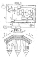
- FIG. 1 partially represents a possible arrangement of the transmission-reception means of an ultrasound system usable with an ultrasound probe according to the above definition and the diagram shows more particularly a transmission-reception channel 10 associated with one of the piezoelectric transducer elements T i from one of the groups constituting the probe.
- This transducer element is connected to a transmitter 11, known per se, responsible for transmitting to it, with each shot, an ultrasonic pulse at the chosen frequency. It is also connected to an amplifier 12 responsible for amplifying the echoes received subsequently by this same transducer.
- a means of shaping 13 (trigger for example) of a control pulse and connected to the input of an adder 14 which also receives on its other input the output signal of the amplifier 12.
- the output of the summer 14 is connected to the input of a first delay line 15 whose outputs are respectively connected to the inputs of a first multiplexer 16.
- the output of the latter is connected to the input of a second line to delays 18 whose outputs are respectively connected to the inputs of a second multiplexer 19.
- the "available" delays at the outputs of the delay lines 15 and 18 differ by an order of magnitude, so that one can obtain any delay (in the range of delays necessary to obtain a desired sector scan) and with the required precision, by addressing the multiplexers 16 and 19, each selecting an output of the corresponding delay line.
- the output of the multiplexer 19 is connected, on the one hand, to an input of an amplifier-summing SOM, receiving on other inputs the delayed signals coming from other similar transmission-reception channels and, on the other hand on the other hand, at the trigger input 22 of a pulse generator 23 responsible for developing, on each shot, an excitation pulse from the transmitter 11, delayed by a desired time with respect to the pulse delivered by the shaping means 13, this time being determined by the state of the multiplexers 16 and 19.
- the control software determines the duration of the excitation pulse by a control link 24 between the microprocessor-sequencer 26 and the generator 23.
- This microprocessor-sequencer 26 and an associated program memory 27 constitute the essential part of the software for controlling the different channels 10.
- the microprocessor thus controls an address generator 30 which controls the two multiplexers 16 and 19 of each channel (addressing links 31 and 3 2).
- the microprocessor is coupled to the memory 27 in order to select therein the reading of the instructions corresponding to a given sequencing resulting from the combination of the parameters chosen by the operator, in particular the frequency of the ultrasound.
- the processor organizes the reading of a certain number of instructions from the program memory, governing the timing of the ultrasonic shots, their orientations (that is to say the corresponding delay laws). to determine the electronic sector scan, the waiting times between shots, ect ...
- the processor 26 For the excitation of a transmitter 11, the processor 26 emits a firing order transmitted by the connecting wire 35 by means of shaping 13 and this order is delayed as a function of the prior positioning of the multiplexers 16 and 19 of the channel corresponding transceiver 10. This command triggers the pulse generator 23 which excites the transmitter 11 during a time interval controlled by the control software. On reception, the echoes picked up by the same transducer element T i are applied to the input of the amplifier 12 and directed towards the set of delay lines 15, 18, to undergo the same delays there before being applied at the corresponding input of the SOM amplifier-summator, thus achieving focus on reception.
- the output signals of the SOM amplifier-summator are processed (in particular windowed) before being used as video signals from a television receiver on which the image is reconstructed line by line into several adjacent angular sectors corresponding to the number of groups of transducer elements defined in the probe.
- FIG. 2 illustrates a possible embodiment of an ultrasonic probe according to the invention, designed to operate with the system of FIG. 1.
- the probe comprises three groups G1, G2 and G3 of transducer elements T i aligned along consecutive portions of a convex contour formed here of consecutive straight portions d1, d2 and d3, forming obtuse angles between them.
- each group G1, G2 or G3 comprises the same number of transducer elements and each transducer element T i is coupled to a transmission-reception channel 10 in accordance with FIG. 1.
- the outputs of the channels corresponding to the elements of each group are respectively connected to the inputs of three summing amplifiers SOM1, SOM2, and SOM3, so that the output signals of these three amplifiers can be used simultaneously.
- the control means of the transmission-reception channels that is to say essentially the processor 26 and the program memory 27
- the system is designed to generate three shots of ultrasound simultaneously, each shot using all the elements of a group G1, G2, G3 by associating each time with each group a predetermined delay law, defining both the focal characteristics of the ultrasound beam emitted and its orientation relative to the emissive surface of the corresponding group.
- the signals collected by the transducer elements of each group are delayed with respect to each other, by application of the same delay laws, before being added by the corresponding amplifier-summator SOM1, SOM2 or SOM3.
- the output signals of these amplifiers are processed in a conventional manner to produce three distinct video signals applied substantially simultaneously to a television monitor (not shown) to modulate three scanning lines respectively registering in three adjacent sectors of the image.
- the frame rate has been multiplied by the number of groups without significantly increasing the complexity of the associated electronic circuits since the number of transducer elements is approximately equal to that of a linear strip operating in "phase array".
- a linear strip operating in "phase array"
- such a conventional linear strip requires 64 transducer elements to electronically scan an angular sector of 90 °, with significant delays for certain transducer elements.
- the same angular sector is scanned three times faster by association of three adjacent angular sectors of 30 ° scanned, each by a group G1, G2 or G3 of 22 transducer elements (a total of 66 channels of transmission-reception 10).
- the delay laws relating to each group implement much lower delay values, therefore delay lines which are easier to build with the required precision and therefore less expensive.
- each group can indeed assign to each group a scan of 45 ° or a total opening of 135 °. If an inter-element pitch equal to the wavelength of the ultrasound and 32 elements per group is chosen, the width of a group is 16 mm for an operating frequency of 3 MHz and the entire emitting surface of the probe falls within an average radius of 22 mm.
- the associated ultrasound system of course comprises 96 transmission-reception channels. To avoid or limit the interference between the echoes coming from simultaneous shots made from the three groups, it is advantageous to choose the delay laws so that the directions of the three shots always make angles of 45 ° with respect to each other.
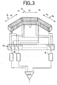
- FIG. 3 illustrates another embodiment for which the frame rate is the same as in a conventional system but with approximately three times less electronic processing circuits.
- the actual probe is the same as before, that is to say that each group G1, G2 and G3 has the same number of transducer elements.
- the transceiver means comprise only a number of transceiver channels 10 equal to the number of transducer elements of a group while sequential switching means, in the form of a multiplexer 35 , are inserted between the groups G1, G2 and G3 and the transmission-reception channels 10 (only 22 in the example described, the signal outputs of these channels being connected to a single amplifier- summing device SOM) to interconnect cyclically and in a given order, the transducer elements T i of the groups and said transmission-reception channels 10.
- the multiplexer 35 is for example made up of a plurality of analog gates connected so as to have three inputs for one output.
- the processor 26 and the memory 27 control, by example, the multiplexer as follows.
- all the elements of group G1 are connected to the transmission-reception channels 10 during all the time of the transmission-reception sequences ensuring a first scan of a sector of 30 °.
- the group G2 is substituted for the group G1 by switching the multiplexer and the transducer elements of the group G2 are connected to the transmission-reception channels during the time of a second scan of a sector of 30 ° adjacent to the previous one.
- all the elements of group G3 are connected to the same transmission-reception channels for the time of a third scan of an adjacent 30 ° sector.
- FIG. 4 where the probe has been modified so that the two lateral groups G1 and G3 located symmetrically on either side of a central group G2 each have a number of transducer elements equal to half the number of transducer elements of said central group.
- This configuration has certain advantages when it is desired that the central zone of the image be of very good quality while retaining a large angular field, the lateral zones then being used mainly for tracking.
- the central group G2 can cover an angular field of only 30 ° and have 64 transducer elements while the lateral groups G1 and G3 can cover an angular field of 45 ° each but have only 32 elements per group.
- Sequential switching means in the form of a multiplexer 36, are interposed between the probe and the transmission-reception means of the ultrasound system, which then comprise as many transmission-reception channels 10 as the central group G2 comprises transducer elements T i .
- This multiplexer 36 has two inputs for one output per switching unit. The inputs are connected to the probe to connect in turn and cyclically the output wires of the transducer elements of the central group G2 to the different transmission-reception channels 10 then the output wires of the transducer elements of the lateral groups G1 and G3 with these same transmission-reception channels 10.
- the successive switching operations of the multiplexer are controlled by the ultrasound system control software essentially comprising the processor 26 and the program memory 27.
- FIG. 5 schematically shows in profile a probe similar to that of FIG. 2 in which the three emissive faces of the groups G1, G2 and G3 are coated with a layer 40 of material, for example an elastometer material, materializing an external surface continuous convex with constant radius of curvature in the plane of the region to be imaged, i.e. the plane of the drawing.
- a layer 40 of material for example an elastometer material, materializing an external surface continuous convex with constant radius of curvature in the plane of the region to be imaged, i.e. the plane of the drawing.
- a layer of elastomeric material 40a can be placed on the surface of the central group G2.
- the convex external surface of the layer of elastomeric material material izes a convex external surface of radii of constant curvature and center O, connecting continuously to the curved emissive surfaces of groups G1 and G2.
- the elastomeric material thus arranged has a "lens" effect providing average focusing in the direction perpendicular to the image plane.
- the opposite configuration to that of FIG. 6 can also give good results.
- the two lateral groups G1, G3 would have their transducer elements arranged along straight portions and the central group G2 would have their elements arranged along a curved portion, for example an arc of a circle, the elastomeric material mentioned above. covering the emissive surfaces of the transducer elements of groups G1 and G3.
Landscapes
- Engineering & Computer Science (AREA)
- Physics & Mathematics (AREA)
- Acoustics & Sound (AREA)
- Radar, Positioning & Navigation (AREA)
- Remote Sensing (AREA)
- Multimedia (AREA)
- Computer Networks & Wireless Communication (AREA)
- General Physics & Mathematics (AREA)
- Investigating Or Analyzing Materials By The Use Of Ultrasonic Waves (AREA)
- Ultra Sonic Daignosis Equipment (AREA)
- Measurement Of Velocity Or Position Using Acoustic Or Ultrasonic Waves (AREA)
Applications Claiming Priority (2)
| Application Number | Priority Date | Filing Date | Title |
|---|---|---|---|
| FR8414708A FR2570837B1 (fr) | 1984-09-25 | 1984-09-25 | Sonde a ultrasons pour balayage sectoriel electronique et echographe incorporant une telle sonde |
| FR8414708 | 1984-09-25 |
Related Parent Applications (1)
| Application Number | Title | Priority Date | Filing Date |
|---|---|---|---|
| EP85401859.5 Division | 1985-09-24 |
Publications (1)
| Publication Number | Publication Date |
|---|---|
| EP0311150A1 true EP0311150A1 (de) | 1989-04-12 |
Family
ID=9308049
Family Applications (2)
| Application Number | Title | Priority Date | Filing Date |
|---|---|---|---|
| EP88119008A Withdrawn EP0311150A1 (de) | 1984-09-25 | 1985-09-24 | Ultraschallsonde zur elektronischen Sektorabtastung und damit ausgestattetes Echoskop |
| EP85401859A Withdrawn EP0177407A1 (de) | 1984-09-25 | 1985-09-24 | Ultraschallsonde zur elektronischen Sektorabtastung und damit ausgestattetes Echoskop |
Family Applications After (1)
| Application Number | Title | Priority Date | Filing Date |
|---|---|---|---|
| EP85401859A Withdrawn EP0177407A1 (de) | 1984-09-25 | 1985-09-24 | Ultraschallsonde zur elektronischen Sektorabtastung und damit ausgestattetes Echoskop |
Country Status (3)
| Country | Link |
|---|---|
| US (1) | US4694700A (de) |
| EP (2) | EP0311150A1 (de) |
| FR (1) | FR2570837B1 (de) |
Cited By (2)
| Publication number | Priority date | Publication date | Assignee | Title |
|---|---|---|---|---|
| FR2836556A1 (fr) * | 2002-02-22 | 2003-08-29 | Marais Atel Du | Dispositif a ultrasons permettant de capter et reproduire des formes tridimensionnelles a partir de cibles pour mesurer des volumes |
| CN105283913A (zh) * | 2013-02-28 | 2016-01-27 | 通用电气公司 | 在asic上用于超声波束成形的德尔塔延迟方法 |
Families Citing this family (14)
| Publication number | Priority date | Publication date | Assignee | Title |
|---|---|---|---|---|
| US4831601A (en) * | 1986-10-31 | 1989-05-16 | Siemens Aktiengesellschaft | Apparatus for transmitting and receiving ultrasonic signals |
| US4888720A (en) * | 1987-12-07 | 1989-12-19 | Fryer Glenn E | Tunnel measuring apparatus and method |
| FR2628539B1 (fr) * | 1988-03-11 | 1991-12-20 | Cgr Ultrasonic | Sonde, dispositif d'imagerie utilisant une telle sonde et procede mettant en oeuvre un tel dispositif |
| US5078147A (en) * | 1990-01-25 | 1992-01-07 | Vivo Corporation | Method of noninvasive ultrasonic detection of nerve root inflammation |
| US7497828B1 (en) * | 1992-01-10 | 2009-03-03 | Wilk Ultrasound Of Canada, Inc. | Ultrasonic medical device and associated method |
| US5337289A (en) * | 1993-07-16 | 1994-08-09 | The United States Of America As Represented By The Department Of Energy | Phased-array ultrasonic surface contour mapping system and method for solids hoppers and the like |
| US8162859B2 (en) * | 2005-06-09 | 2012-04-24 | General Patent , LLC | Shock wave treatment device and method of use |
| EP1736799B8 (de) * | 2005-06-16 | 2013-05-29 | Kabushiki Kaisha Toshiba | Verfahren zur Optimierung von Ultraschallübertragung/-empfang, entsprechendes Programm und diagnostisches Ultraschallgerät |
| KR20080093281A (ko) * | 2007-04-16 | 2008-10-21 | 주식회사 메디슨 | 초음파 진단용 프로브 |
| EP3103396B1 (de) * | 2015-06-10 | 2018-10-24 | Helmholtz Zentrum München Deutsches Forschungszentrum für Gesundheit und Umwelt GmbH | Vorrichtung und verfahren zur hybriden optoakustischen tomografie und ultraschallsonografie |
| WO2017106834A1 (en) * | 2015-12-18 | 2017-06-22 | Ursus Medical, Llc | Ultrasound beamforming system and method with reconfigurable aperture |
| DE102019106427B4 (de) * | 2019-03-13 | 2022-04-28 | Bundesrepublik Deutschland, vertreten durch den Bundesminister für Wirtschaft und Energie, dieser vertreten durch den Präsidenten der Bundesanstalt für Materialforschung und –prüfung (BAM) | Wandler und Wandleranordnung für Ultraschall-Prüfkopfsysteme, Ultraschall-Prüfkopfsystem und Prüfverfahren |
| FR3142340A1 (fr) | 2022-11-30 | 2024-05-31 | Echopen Factory | Sonde échographique polyvalente à transducteur mut à balayage mécanique |
| FR3142339B1 (fr) | 2022-11-30 | 2024-10-11 | Echopen Factory | Sonde échographique polyvalente à plusieurs transducteurs monoéléments à balayage mécanique oscillant |
Citations (4)
| Publication number | Priority date | Publication date | Assignee | Title |
|---|---|---|---|---|
| GB2079102A (en) * | 1980-06-27 | 1982-01-13 | Matsushita Electric Industrial Co Ltd | Arc scan transducer array having a diverging lens |
| US4344327A (en) * | 1979-12-28 | 1982-08-17 | Aloka Co., Ltd. | Electronic scanning ultrasonic diagnostic system |
| US4409982A (en) * | 1980-10-20 | 1983-10-18 | Picker Corporation | Ultrasonic step scanning utilizing curvilinear transducer array |
| US4462092A (en) * | 1980-05-15 | 1984-07-24 | Matsushita Electric Industrial Company, Limited | Arc scan ultrasonic transducer array |
Family Cites Families (10)
| Publication number | Priority date | Publication date | Assignee | Title |
|---|---|---|---|---|
| IT987930B (it) * | 1972-11-02 | 1975-03-20 | Cecchettini Giancarlo | Apparecchio per ginnastica |
| DK134499B (da) * | 1974-11-19 | 1976-11-15 | Akad Tekn Videnskaber | Apparat til tilvejebringelse af et ultralydsnitbillede til brug ved måling af kød- og spækfordelingen på biologisk materiale. |
| CA1093674A (en) * | 1975-10-13 | 1981-01-13 | George Kossoff | Ultrasonic beam scanning |
| FR2332531A1 (fr) * | 1975-11-24 | 1977-06-17 | Commissariat Energie Atomique | Camera ultra-sonore |
| DE2657163A1 (de) * | 1976-12-17 | 1978-06-22 | Hugo Werner Prof Dr Buschmann | Geraet zur ultraschalluntersuchung im schnittbildverfahren mit kombinierter elektromechanischer und elektronischer aenderung der schallbuendelposition |
| US4200858A (en) * | 1976-12-28 | 1980-04-29 | Canon Kabushiki Kaisha | Acoustic wave scanning apparatus |
| DE2711098C3 (de) * | 1977-03-14 | 1980-04-10 | Siemens Ag, 1000 Berlin Und 8000 Muenchen | Vorrichtung zur Untersuchung von Körpern durch Ultraschallabtastung |
| US4276779A (en) * | 1979-03-29 | 1981-07-07 | Raytheon Company | Dynamically focussed array |
| JPS56155874A (en) * | 1980-05-06 | 1981-12-02 | Matsushita Electric Ind Co Ltd | Ultrasonic beam scanner |
| EP0134346B1 (de) * | 1983-08-25 | 1989-05-31 | Analogic Corporation | Ultraschallwandler |
-
1984
- 1984-09-25 FR FR8414708A patent/FR2570837B1/fr not_active Expired
-
1985
- 1985-09-24 EP EP88119008A patent/EP0311150A1/de not_active Withdrawn
- 1985-09-24 EP EP85401859A patent/EP0177407A1/de not_active Withdrawn
- 1985-09-25 US US06/779,855 patent/US4694700A/en not_active Expired - Fee Related
Patent Citations (5)
| Publication number | Priority date | Publication date | Assignee | Title |
|---|---|---|---|---|
| US4344327A (en) * | 1979-12-28 | 1982-08-17 | Aloka Co., Ltd. | Electronic scanning ultrasonic diagnostic system |
| US4344327B1 (en) * | 1979-12-28 | 1994-05-03 | Aloka Co Ltd | Electronic scanning ultrasonic diagnostic system |
| US4462092A (en) * | 1980-05-15 | 1984-07-24 | Matsushita Electric Industrial Company, Limited | Arc scan ultrasonic transducer array |
| GB2079102A (en) * | 1980-06-27 | 1982-01-13 | Matsushita Electric Industrial Co Ltd | Arc scan transducer array having a diverging lens |
| US4409982A (en) * | 1980-10-20 | 1983-10-18 | Picker Corporation | Ultrasonic step scanning utilizing curvilinear transducer array |
Cited By (3)
| Publication number | Priority date | Publication date | Assignee | Title |
|---|---|---|---|---|
| FR2836556A1 (fr) * | 2002-02-22 | 2003-08-29 | Marais Atel Du | Dispositif a ultrasons permettant de capter et reproduire des formes tridimensionnelles a partir de cibles pour mesurer des volumes |
| CN105283913A (zh) * | 2013-02-28 | 2016-01-27 | 通用电气公司 | 在asic上用于超声波束成形的德尔塔延迟方法 |
| CN105283913B (zh) * | 2013-02-28 | 2019-09-24 | 通用电气公司 | 在asic上用于超声波束成形的德尔塔延迟方法 |
Also Published As
| Publication number | Publication date |
|---|---|
| US4694700A (en) | 1987-09-22 |
| EP0177407A1 (de) | 1986-04-09 |
| FR2570837A1 (fr) | 1986-03-28 |
| FR2570837B1 (fr) | 1987-11-20 |
Similar Documents
| Publication | Publication Date | Title |
|---|---|---|
| EP0311150A1 (de) | Ultraschallsonde zur elektronischen Sektorabtastung und damit ausgestattetes Echoskop | |
| EP0150634B1 (de) | Ultraschallwandler für Echographie mit einer eine convexe Oberfläche formende Matrix von Wandlerelementen | |
| EP0119911B1 (de) | Verfahren zur Ultraschallabbildung mittels auf einer geraden Linie angeordneten Wandlerelemente | |
| EP0591061B1 (de) | Verfahren und Vorrichtung zur akustischen Prüfung mit Zeitumkehrsignalen | |
| EP0459583B1 (de) | Ultraschallbildgerät mit adaptiver Phasenaberrationskorrektur | |
| FR2763166A1 (fr) | Reseau de transducteurs a ultrasons et systeme d'imagerie utilisant un tel reseau | |
| FR2485738A1 (fr) | Reseau de transducteurs pour balayage en arc comportant une lentille divergente | |
| EP0383650A1 (de) | Verfahren und Vorrichtung zum Orten und Fokussieren von Wellen | |
| FR2763699A1 (fr) | Detecteur-optoelectronique | |
| EP0543445A1 (de) | Untersuchungsgerät von Medien mittels Ultraschall-Echographie | |
| FR2467413A1 (fr) | Procede et dispositif pour proceder a des examens a l'aide de faisceaux d'ultrasons | |
| EP0420346B1 (de) | Ultraschall-Echograph mit digitaler Einrichtung zur Formung des Strahlenbündels im Empfangsfall | |
| EP0733408A1 (de) | Ultraschallsensor und Messverfahren unter Verwendung eines derartigen Sensors | |
| EP0069677B1 (de) | Vorrichtung für Ultraschall-Echographie zur Sektorabtastung | |
| EP0106418B1 (de) | Gerät zum Untersuchen von Medien mittels Ultraschallechographie | |
| EP1350123A1 (de) | Verfahren, system und sonde zur bilderfassung | |
| EP0133135A2 (de) | Ultraschallmultisensor mit Sensoren von verschiedenen Grössen | |
| EP1430299B1 (de) | Vorrichtung zur strukturanalyse eines materials | |
| FR3065078B1 (fr) | Procede et dispositif de sondage ultrasonore par focalisation adaptative au moyen d'un objet solide reverberant | |
| FR2562676A1 (fr) | Dispositif pour le traitement des signaux modules recus par un systeme sonar | |
| FR2582107A1 (fr) | Procede et dispositif pour la determination de la signature d'emission a grande distance d'un ensemble d'emission sismique | |
| EP0054045B1 (de) | Empfangsgerät für eine, mit einer mehrfachelement-ultraschallsonde versehene, echographische vorrichtung | |
| FR2508665A1 (fr) | Procede d'imagerie ultrasonore dynamique pour imageur a sonde multi-elements | |
| CA1260602A (fr) | Procede pour ameliorer la restitution des images fournies par un sonar lateral et dispositif pour sa mise en oeuvre | |
| FR2482732A1 (fr) | Dispositif d'echographie a focalisation dynamique et a balayage sectoriel |
Legal Events
| Date | Code | Title | Description |
|---|---|---|---|
| PUAI | Public reference made under article 153(3) epc to a published international application that has entered the european phase |
Free format text: ORIGINAL CODE: 0009012 |
|
| AC | Divisional application: reference to earlier application |
Ref document number: 177407 Country of ref document: EP |
|
| AK | Designated contracting states |
Kind code of ref document: A1 Designated state(s): DE GB IT NL |
|
| 17P | Request for examination filed |
Effective date: 19890503 |
|
| 17Q | First examination report despatched |
Effective date: 19911031 |
|
| STAA | Information on the status of an ep patent application or granted ep patent |
Free format text: STATUS: THE APPLICATION IS DEEMED TO BE WITHDRAWN |
|
| 18D | Application deemed to be withdrawn |
Effective date: 19920311 |