EP0054045B1 - Empfangsgerät für eine, mit einer mehrfachelement-ultraschallsonde versehene, echographische vorrichtung - Google Patents
Empfangsgerät für eine, mit einer mehrfachelement-ultraschallsonde versehene, echographische vorrichtung Download PDFInfo
- Publication number
- EP0054045B1 EP0054045B1 EP81901690A EP81901690A EP0054045B1 EP 0054045 B1 EP0054045 B1 EP 0054045B1 EP 81901690 A EP81901690 A EP 81901690A EP 81901690 A EP81901690 A EP 81901690A EP 0054045 B1 EP0054045 B1 EP 0054045B1
- Authority
- EP
- European Patent Office
- Prior art keywords
- unit
- elements
- delay
- control circuit
- line length
- Prior art date
- Legal status (The legal status is an assumption and is not a legal conclusion. Google has not performed a legal analysis and makes no representation as to the accuracy of the status listed.)
- Expired
Links
- 239000000523 sample Substances 0.000 title claims abstract description 20
- 230000001934 delay Effects 0.000 description 6
- 238000001444 catalytic combustion detection Methods 0.000 description 5
- 238000002604 ultrasonography Methods 0.000 description 4
- 230000005284 excitation Effects 0.000 description 2
- 238000010200 validation analysis Methods 0.000 description 2
- 230000005540 biological transmission Effects 0.000 description 1
- 230000008878 coupling Effects 0.000 description 1
- 238000010168 coupling process Methods 0.000 description 1
- 238000005859 coupling reaction Methods 0.000 description 1
- 239000013078 crystal Substances 0.000 description 1
- 230000003111 delayed effect Effects 0.000 description 1
- 238000003745 diagnosis Methods 0.000 description 1
- 238000010586 diagram Methods 0.000 description 1
- 238000002592 echocardiography Methods 0.000 description 1
- 238000005516 engineering process Methods 0.000 description 1
- 238000005259 measurement Methods 0.000 description 1
- 230000002572 peristaltic effect Effects 0.000 description 1
Images

Classifications
-
- A—HUMAN NECESSITIES
- A61—MEDICAL OR VETERINARY SCIENCE; HYGIENE
- A61B—DIAGNOSIS; SURGERY; IDENTIFICATION
- A61B8/00—Diagnosis using ultrasonic, sonic or infrasonic waves
-
- G—PHYSICS
- G01—MEASURING; TESTING
- G01S—RADIO DIRECTION-FINDING; RADIO NAVIGATION; DETERMINING DISTANCE OR VELOCITY BY USE OF RADIO WAVES; LOCATING OR PRESENCE-DETECTING BY USE OF THE REFLECTION OR RERADIATION OF RADIO WAVES; ANALOGOUS ARRANGEMENTS USING OTHER WAVES
- G01S15/00—Systems using the reflection or reradiation of acoustic waves, e.g. sonar systems
- G01S15/88—Sonar systems specially adapted for specific applications
- G01S15/89—Sonar systems specially adapted for specific applications for mapping or imaging
- G01S15/8906—Short-range imaging systems; Acoustic microscope systems using pulse-echo techniques
- G01S15/8909—Short-range imaging systems; Acoustic microscope systems using pulse-echo techniques using a static transducer configuration
- G01S15/8915—Short-range imaging systems; Acoustic microscope systems using pulse-echo techniques using a static transducer configuration using a transducer array
- G01S15/8918—Short-range imaging systems; Acoustic microscope systems using pulse-echo techniques using a static transducer configuration using a transducer array the array being linear
-
- G—PHYSICS
- G01—MEASURING; TESTING
- G01S—RADIO DIRECTION-FINDING; RADIO NAVIGATION; DETERMINING DISTANCE OR VELOCITY BY USE OF RADIO WAVES; LOCATING OR PRESENCE-DETECTING BY USE OF THE REFLECTION OR RERADIATION OF RADIO WAVES; ANALOGOUS ARRANGEMENTS USING OTHER WAVES
- G01S7/00—Details of systems according to groups G01S13/00, G01S15/00, G01S17/00
- G01S7/52—Details of systems according to groups G01S13/00, G01S15/00, G01S17/00 of systems according to group G01S15/00
- G01S7/52017—Details of systems according to groups G01S13/00, G01S15/00, G01S17/00 of systems according to group G01S15/00 particularly adapted to short-range imaging
- G01S7/52023—Details of receivers
- G01S7/52025—Details of receivers for pulse systems
-
- G—PHYSICS
- G10—MUSICAL INSTRUMENTS; ACOUSTICS
- G10K—SOUND-PRODUCING DEVICES; METHODS OR DEVICES FOR PROTECTING AGAINST, OR FOR DAMPING, NOISE OR OTHER ACOUSTIC WAVES IN GENERAL; ACOUSTICS NOT OTHERWISE PROVIDED FOR
- G10K11/00—Methods or devices for transmitting, conducting or directing sound in general; Methods or devices for protecting against, or for damping, noise or other acoustic waves in general
- G10K11/18—Methods or devices for transmitting, conducting or directing sound
- G10K11/26—Sound-focusing or directing, e.g. scanning
- G10K11/34—Sound-focusing or directing, e.g. scanning using electrical steering of transducer arrays, e.g. beam steering
- G10K11/341—Circuits therefor
Definitions
- the present invention relates to a receiver device for an ultrasound scanner with multi-element ultrasonic probe. It relates more particularly to the field of ultrasonic medical diagnosis.
- piezoelectric transmitter-receiver devices These piezoelectric devices or probes allow ultrasonic waves to be emitted when the piezoelectric crystals are excited by electrical pulses at a predetermined emission frequency. The waves emitted propagate in the medium of which one seeks to produce an image. They are partly reflected by differences in acoustic impedance between the inhomogeneous media encountered. The reflections are called echoes. These are pressure waves that the piezoelectric probe translates into an electrical pulse, called response echo signals.
- the ultrasonic wave having a certain speed of propagation in the medium, each echo is received after the emission on a date which depends on the distance to the obstacle which returns it.
- the probe comprises N adjacent elements.
- the ultrasonic beam is generated by the excitation of P adjacent elements taken from among the N elements of the probe.
- predetermined time delays which vary from one element to another, it is possible to focus the ultrasonic energy of the beam at a determined point called the focus of examination.
- the time delay law applied to each transducer element of the probe is such that the focal point obtained can be angularly displaced around the axis of the probe.
- each echo signal received is transmitted to the signal processing device through a delay line adjustable by the electronic control circuit means.
- each delay line is capable of providing delays as small as possible and delays exceeding the second.
- the delay laws applied to these delay line elements must be such that the diferent signals transmitted to the processing device correspond at a given moment to the same echo reflected by the obstacle.
- CCD Charge Coupled Device
- any signal presented at the input is transmitted progressively at a certain rate of input analysis and at a crossing rate which are determined by a clock signal which can vary in wide frequency ranges which determine the dynamics and therefore the characteristics of the ultrasonic beam received.
- the clock frequency is diversified as a function of the reception angle and therefore of the transducer element concerned.
- the setting of the clock frequencies must be done quickly and with a given precision.
- the electronic circuits necessary for such an implementation increase the cost of the examination equipment. This is particularly the case where the frequency is adjusted in a synthesizer by means of an oscillator controlled by VCO voltage.
- Another problem posed by delay line service devices is temperature drift. Finally, it is also necessary to compensate for the voltage dependence.
- the invention relates to a receiver device of the kind mentioned last in the introduction.
- the invention therefore relates to a receiver device for an ultrasound system comprising an ultrasound probe comprising a plurality of transducer elements, a corresponding number of units of charge transfer elements interconnected respectively between each transducer and a summing means, said units being intended for store echo signals delivered according to a reception sequence predetermined by the transducer elements, and a control circuit controlling the storage and reading of the stored echo signals and determining, for each unit, a delay for triggering the storage, said circuit comprising a clock, characterized in that for each unit the control circuit comprises a delay means, a gate and a line length counter determining the duration during which the echo signals are admitted to the associated unit, each delay means being connected between said clock and the associated door, the output of which is connected to a command input for the associated unit as well as associated line length counter, the control circuit further comprising an operating control circuit delivering digital codes for programming each sequence, on the one hand, each of said delay means and, on the other hand, each of said length counters of line, each delay means and each line length counter comprising
- a probe 1 comprises a plurality of transducer elements 11 which, excited by a pulse generator comprising as many channels as there are transducers, emit an ultrasonic wave focused at point A.
- This probe constitutes a beam inclined under the angle a with the perpendicular to the linear probe.
- the sensor excitation pulse generator known in itself, has not been shown in the drawing.
- the wave concentrated at point A is partly re-emitted by it and returns in the form of an ultrasonic echo to the transducer elements 11 to 1N.
- the transducer element in response to the ultrasonic wave which it receives, generates a signal called echo signal X1 to XN which is transmitted to a summing-amplifier 8 through a delay line 71 to 7N. Delays on the delay line are controlled by a delay circuit 31 to 3N.
- Each delay circuit 31 to 3N receives on the one hand a timing command C1 to CN of a clock 6 and on the other hand, an operating command S1 to SN of an operating control circuit 2.
- Each delay line 71 to 7N receives the command D1 to DN of the delay signals 31 to 3N via the input-output logic 51 to 5N.
- Each of these logic units 51 to 5N receives a command B1 to BN from an input-output control circuit 4.
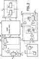
- FIG. 2 a particular embodiment is shown according to the invention.
- This figure shows a data acquisition channel receiving an echo signal X1 transmitted to the summing-amplifier 8.
- a channel comprises a delay line 71, an input-output logic 51, a delay circuit 31 which receives commands from the operating control circuit 2 not shown here, an input-output control circuit 4 and the clock 6.
- the operating control circuit supplies the signals EA1, EB1 and EC1 respectively to circuits 31 and 4.
- the operating control gives the so-called starting signal S1 to SN after sending the transmission pulse.
- a delay time counter 111 is thus activated.
- the counter 111 is loaded by its input EA1 at an initial value which is counted down to the zero value where it emits a signal of zero.
- This signal composed with the signal C1 supplied by the clock 6 in an AND gate, transmits the clock signal C1 to a divider 121.
- the divider 121 divides the frequency of the clock signal C1 by a factor Z.
- the signal with divided frequency is transmitted to a line length counter 131 which has been brought by control 2 by its input EB1 to a fixed value.
- the counter 131 makes it possible, according to the position of an electronic switch, to set the rate of the measurement signal X1 through logic 51 in the delay line 71.
- This electronic switch is here constituted by a flip-flop 14 in the circuit 4 input-output control.
- the flip-flop 14 generates a signal B1 to BN transmitted to the input-output logic 51.
- Signal B1 is composed via four gates AND at signal A1 provides flip-flops 15 and 16.
- the useful signal is completely recorded in one of the CCDs 71A or 71B of the delay line 71. And the cadence stops. It is only when all the line length counters 131 to 13N are reset to zero that the useful information can be extracted by applying the release signal F. When all the line counters 131 are at zero, an element electronic switching, here produced by a flip-flop 15, reverses and remains in this state as long as an output counter is running. During this time, the CCDs which previously received the useful signal are emptied in parallel. When they are all empty, the pace stops.
- the switch 14 and the switch 15 to release one or the other of the groups of CCDs A or B, that is to say, to release the CCDs 71 A to 7NA then prepare the other group for the entry of a new useful signal 71 B to 7NB.
- the output counter 17 is not reset to this state until the output has been completed.
- Another switch existing in the input-output command for example a flip-flop 16, allows the pulse to be provided at the output. It switches on the falling edge of the signal coming from the pilot clock 9 of the clock 6.
- the frequency of this clock has been divided by the sector Z / 2 in a divider 10. It is thus ensured that, whatever the instant of inversion of the electronic switch 15, the timing of the useful signal is done on a blank of the clock signal and not at the moment of the change of state of the switch 15.
- the use of the clock frequency signal divided by a factor Z / 2 gives the assurance that the inaccuracy of the time of delay will only be of the order of a cycle of the pilot frequency 9.
- the use of two CCDs 71 A and 71 B is advantageous in that while outputting previous useful information, it is possible simultaneously, but after having delayed the start of the recording, to enter new useful information.
- PCCD elements in English Peristaltic Charge Coupled Device
- PCCD elements are well known for their speed of operation (up to one hundred megahertz). They find application in the invention where they allow faster data rates.
Landscapes
- Engineering & Computer Science (AREA)
- Physics & Mathematics (AREA)
- Radar, Positioning & Navigation (AREA)
- Remote Sensing (AREA)
- Life Sciences & Earth Sciences (AREA)
- Acoustics & Sound (AREA)
- Health & Medical Sciences (AREA)
- Computer Networks & Wireless Communication (AREA)
- General Physics & Mathematics (AREA)
- Pathology (AREA)
- Surgery (AREA)
- Nuclear Medicine, Radiotherapy & Molecular Imaging (AREA)
- Multimedia (AREA)
- Radiology & Medical Imaging (AREA)
- Biomedical Technology (AREA)
- Heart & Thoracic Surgery (AREA)
- Medical Informatics (AREA)
- Molecular Biology (AREA)
- Biophysics (AREA)
- Animal Behavior & Ethology (AREA)
- General Health & Medical Sciences (AREA)
- Public Health (AREA)
- Veterinary Medicine (AREA)
- Ultra Sonic Daignosis Equipment (AREA)
- Investigating Or Analyzing Materials By The Use Of Ultrasonic Waves (AREA)
- Measurement Of Velocity Or Position Using Acoustic Or Ultrasonic Waves (AREA)
Claims (3)
Applications Claiming Priority (2)
| Application Number | Priority Date | Filing Date | Title |
|---|---|---|---|
| DE3023386A DE3023386C2 (de) | 1980-06-23 | 1980-06-23 | Schaltungsanordnung für eine Ultraschall-Untersuchungseinrichtung |
| DE3023386 | 1980-06-23 |
Publications (2)
| Publication Number | Publication Date |
|---|---|
| EP0054045A1 EP0054045A1 (de) | 1982-06-23 |
| EP0054045B1 true EP0054045B1 (de) | 1986-08-20 |
Family
ID=6105206
Family Applications (1)
| Application Number | Title | Priority Date | Filing Date |
|---|---|---|---|
| EP81901690A Expired EP0054045B1 (de) | 1980-06-23 | 1981-06-23 | Empfangsgerät für eine, mit einer mehrfachelement-ultraschallsonde versehene, echographische vorrichtung |
Country Status (5)
| Country | Link |
|---|---|
| US (1) | US4499902A (de) |
| EP (1) | EP0054045B1 (de) |
| JP (1) | JPS57500811A (de) |
| DE (1) | DE3023386C2 (de) |
| WO (1) | WO1982000061A1 (de) |
Families Citing this family (3)
| Publication number | Priority date | Publication date | Assignee | Title |
|---|---|---|---|---|
| JPS5939198A (ja) * | 1982-08-27 | 1984-03-03 | Victor Co Of Japan Ltd | マイクロホン装置 |
| DE3236218A1 (de) * | 1982-09-30 | 1984-04-05 | Dietmar 5840 Schwerte Demuth | Verfahren und vorrichtung zur digitalen ansteuerung einer verzoegerungskette fuer ein ultraschall-geraet |
| FR2846098B1 (fr) * | 2002-10-22 | 2005-01-14 | Thales Ultrasonics Sas | Dispositif evolutif de traitement rapide de signaux d'antennes a grand nombre d'elements |
Family Cites Families (9)
| Publication number | Priority date | Publication date | Assignee | Title |
|---|---|---|---|---|
| JPS5143879A (de) * | 1974-09-30 | 1976-04-14 | Tokyo Shibaura Electric Co | |
| JPS5540829B2 (de) * | 1975-01-13 | 1980-10-20 | ||
| US4001763A (en) * | 1975-02-03 | 1977-01-04 | Raytheon Company | Electronically stabilized beam former system |
| US4317370A (en) * | 1977-06-13 | 1982-03-02 | New York Institute Of Technology | Ultrasound imaging system |
| US4227417A (en) * | 1977-06-13 | 1980-10-14 | New York Institute Of Technology | Dynamic focusing apparatus and method |
| US4267584A (en) * | 1977-07-01 | 1981-05-12 | Siemens Gammasonics, Inc. | Permutating analog shift register variable delay system |
| US4173007A (en) * | 1977-07-01 | 1979-10-30 | G. D. Searle & Co. | Dynamically variable electronic delay lines for real time ultrasonic imaging systems |
| US4159462A (en) * | 1977-08-18 | 1979-06-26 | General Electric Company | Ultrasonic multi-sector scanner |
| US4257271A (en) * | 1979-01-02 | 1981-03-24 | New York Institute Of Technology | Selectable delay system |
-
1980
- 1980-06-23 DE DE3023386A patent/DE3023386C2/de not_active Expired
-
1981
- 1981-06-23 EP EP81901690A patent/EP0054045B1/de not_active Expired
- 1981-06-23 WO PCT/FR1981/000082 patent/WO1982000061A1/fr not_active Ceased
- 1981-06-23 JP JP56502109A patent/JPS57500811A/ja active Pending
- 1981-06-23 US US06/355,576 patent/US4499902A/en not_active Expired - Fee Related
Also Published As
| Publication number | Publication date |
|---|---|
| EP0054045A1 (de) | 1982-06-23 |
| DE3023386A1 (de) | 1982-01-14 |
| JPS57500811A (de) | 1982-05-13 |
| US4499902A (en) | 1985-02-19 |
| WO1982000061A1 (fr) | 1982-01-07 |
| DE3023386C2 (de) | 1983-10-27 |
Similar Documents
| Publication | Publication Date | Title |
|---|---|---|
| FR2461265A1 (fr) | Dispositif de formation d'image par ultrasons a commande numerique, notamment pour le diagnostic medical | |
| EP0541434B1 (de) | Verfahren und Vorrichtung zur Ultraschallprüfung von Werkzeugen | |
| EP0337287B1 (de) | Echofolger für ein Ultraschallmessgerät zum Feststellen der Position einer beweglichen Fläche | |
| EP0709673A1 (de) | Vorrichtung zur zerstörungsfreien Prüfung von rohrförmigen Hohlkörpers mit Ultraschall | |
| EP0001532B1 (de) | Ultraschallvorrichtung zum Sichtbarmachen eines dünnen Schnittes aus einem Körper | |
| FR2518638A1 (fr) | Procede et dispositif acoustiques pour la mesure de dimensions transversales d'un trou, notamment dans un puits | |
| US4023175A (en) | Imaging systems | |
| EP0459583A1 (de) | Ultraschallbildgerät mit adaptiver Phasenaberrationskorrektur | |
| EP0335759A1 (de) | Ultraschallwindmesser | |
| FR2589247A1 (fr) | Appareil d'exploration de milieux par echographie ultrasonore comprenant un reseau d'elements transducteurs piezoelectiques | |
| CA2270796C (fr) | Procede de controle ultrasonore en immersion de pieces a geometrie cylindrique | |
| EP0054045B1 (de) | Empfangsgerät für eine, mit einer mehrfachelement-ultraschallsonde versehene, echographische vorrichtung | |
| EP0311150A1 (de) | Ultraschallsonde zur elektronischen Sektorabtastung und damit ausgestattetes Echoskop | |
| CA1123953A (fr) | Dispositif d'enregistrement optique a commande numerique | |
| EP0082763A1 (de) | Überwachungssystem für eine Vielzahl von Behältern mit ultraschallgesicherten Verschlüssen | |
| EP0825453A1 (de) | Verfahren und Anordnung zur Bearbeitung von Signalen, welche durch ein Volumenstruktur reflektierte oder übertragene Wellen darstellen, um eine Forschung und Analyse der Struktur auszuführen | |
| WO2000045137A1 (fr) | Dipositif piezo-electrique de mesure de niveau de liquide | |
| EP1430299B1 (de) | Vorrichtung zur strukturanalyse eines materials | |
| FR2632733A1 (fr) | Suiveur d'echo pour appareil de mesure par ultrasons de la position d'une paroi mobile | |
| EP0040566B1 (de) | Echographisches Gerät mit dynamischer Fokussierung und Sektorabtastung | |
| EP0520563B1 (de) | Ultraschall-Echographie mit adaptiver Phasenaberrationkorrektur | |
| EP0502071B1 (de) | Gerät zur ultraschallprüfung der verkeilung eines werkstücks | |
| FR2582107A1 (fr) | Procede et dispositif pour la determination de la signature d'emission a grande distance d'un ensemble d'emission sismique | |
| FR2761781A1 (fr) | Systeme d'imagerie acoustique | |
| FR2660436A1 (fr) | Microscope acoustique pour analyser un objet en surface ou en profondeur. |
Legal Events
| Date | Code | Title | Description |
|---|---|---|---|
| PUAI | Public reference made under article 153(3) epc to a published international application that has entered the european phase |
Free format text: ORIGINAL CODE: 0009012 |
|
| 17P | Request for examination filed |
Effective date: 19820210 |
|
| AK | Designated contracting states |
Designated state(s): FR |
|
| GRAA | (expected) grant |
Free format text: ORIGINAL CODE: 0009210 |
|
| AK | Designated contracting states |
Kind code of ref document: B1 Designated state(s): FR |
|
| PLBE | No opposition filed within time limit |
Free format text: ORIGINAL CODE: 0009261 |
|
| STAA | Information on the status of an ep patent application or granted ep patent |
Free format text: STATUS: NO OPPOSITION FILED WITHIN TIME LIMIT |
|
| 26N | No opposition filed | ||
| PG25 | Lapsed in a contracting state [announced via postgrant information from national office to epo] |
Ref country code: FR Effective date: 19890630 |
|
| REG | Reference to a national code |
Ref country code: FR Ref legal event code: ST |