EP0311211A1 - Verfahren zum Steuern des Durchgangs einer Textilbahn durch eine Rotationssiebdruckmaschine - Google Patents
Verfahren zum Steuern des Durchgangs einer Textilbahn durch eine Rotationssiebdruckmaschine Download PDFInfo
- Publication number
- EP0311211A1 EP0311211A1 EP88202208A EP88202208A EP0311211A1 EP 0311211 A1 EP0311211 A1 EP 0311211A1 EP 88202208 A EP88202208 A EP 88202208A EP 88202208 A EP88202208 A EP 88202208A EP 0311211 A1 EP0311211 A1 EP 0311211A1
- Authority
- EP
- European Patent Office
- Prior art keywords
- substrate
- printing machine
- length
- leader
- buffer
- Prior art date
- Legal status (The legal status is an assumption and is not a legal conclusion. Google has not performed a legal analysis and makes no representation as to the accuracy of the status listed.)
- Granted
Links
- 238000009434 installation Methods 0.000 title claims abstract description 34
- 239000004744 fabric Substances 0.000 title claims abstract description 31
- 238000000034 method Methods 0.000 title claims abstract description 11
- 238000010022 rotary screen printing Methods 0.000 title claims abstract description 8
- 239000000758 substrate Substances 0.000 claims abstract description 84
- 238000007639 printing Methods 0.000 claims abstract description 52
- 238000012545 processing Methods 0.000 claims abstract description 24
- 238000001035 drying Methods 0.000 claims description 6
- 239000002699 waste material Substances 0.000 abstract description 6
- 238000009958 sewing Methods 0.000 description 3
- 230000001419 dependent effect Effects 0.000 description 2
- 238000004519 manufacturing process Methods 0.000 description 2
- 238000005259 measurement Methods 0.000 description 2
- 238000002203 pretreatment Methods 0.000 description 2
- 238000007650 screen-printing Methods 0.000 description 2
- 238000013459 approach Methods 0.000 description 1
- 230000005540 biological transmission Effects 0.000 description 1
- 239000003086 colorant Substances 0.000 description 1
- 230000001276 controlling effect Effects 0.000 description 1
- 239000000428 dust Substances 0.000 description 1
Images
Classifications
-
- B—PERFORMING OPERATIONS; TRANSPORTING
- B41—PRINTING; LINING MACHINES; TYPEWRITERS; STAMPS
- B41F—PRINTING MACHINES OR PRESSES
- B41F15/00—Screen printers
- B41F15/08—Machines
- B41F15/12—Machines with auxiliary equipment, e.g. for drying printed articles
-
- B—PERFORMING OPERATIONS; TRANSPORTING
- B41—PRINTING; LINING MACHINES; TYPEWRITERS; STAMPS
- B41F—PRINTING MACHINES OR PRESSES
- B41F15/00—Screen printers
- B41F15/08—Machines
- B41F15/0831—Machines for printing webs
- B41F15/0836—Machines for printing webs by means of cylindrical screens or screens in the form of endless belts
Definitions
- the present invention relates to a method for controlling the fabric through a rotary screen printing installation, whereby the substrate to be printed is wound from a stock roll via a wind-off roller and fed to the printing machine of the installation, and the substrate is then fed through a drying installation and wound up.
- a rotary screen printing installation of this type is generally known.
- the object of the present invention is to improve the control of the input such that the down times and/or lower production speeds are reduced.
- a further object of the present invention is the automatic registration of the total number of meter of fabric used and the automatic registration of the number of meters of fabric that is printed with first-choice quality.
- a pre-determined length of a fabric of low quality is fed into the installation for setting the printing machine, a portion being stored in a buffer, - the substrate to be printed is sewn to the leader, - the length of the print order is stored in the memory of an electronic processing unit, - the printing machine is set whilst emptying the buffer, - the intake of substrate is started at low speed, a signal for measuring the length of the substrate fed in being given to the processing unit when the seam between the leader and the substrate passes the wind-off roller, - a signal for measuring the length of the printed substrate of first quality is given to the processing unit when the seam has passed through the printing machine and the printing machine is set to first quality, - the measured length of substrate of first quality is compared with the length of the print order stored in the memory.
- leader being fabric of low quality
- the use of a leader has the advantage that the printing machine can be set (brought into register) on inexpensive fabric, so that the amount of waste of the substrate to be printed, which is mostly expensive, can be kept to a minimum.
- the quantity of leader required which is necessary for bringing the printing machine into register, is known from experience and dependent on the number of printing positions in operation or of colors required.
- the substrate to be printed is measured from the point when the seam between the leader and the substrate passes the wind-off roller, so that the total quantity of substrate fed in is measured.
- a further signal is given to the processing unit from the point when the printing machine is set to print with first quality, so that the length of substrate printed with first quality is also measured.
- the total quantity of substrate and the quantity of substrate of first quality are measured in the processing unit, the latter quantity being compared with the length of the print order previously entered in the processing unit.
- the machine can also be set for a minimum percentage of waste of the substrate to be printed, while, as a result of the presence of the buffer, the down times can be reduced or can be avoided.
- the method according to the invention can be further extended in that: - a signal is given by the electronic processing unit if the difference between the measured length of first quality and the length of the print order is less than a pre-determined value (a), - the speed of the printing machine is brought back to, or kept constant at, a pre-determined value and the speed of the intake is increased to a speed which is much higher than that of the printing machine, so that the buffer is filled, - the feed stops when the length of the substrate required for carrying out the print order has been fed into the intake, - the substrate is cut off and leader sewn firmly onto the trailing end of the substrate, - a signal is given to the processing unit when the seam between the substrate and the leader passes the wind-off roller, by which means the exact quantity of substrate used is known, - the buffer is filled with as much leader as is needed for setting the printing machine for carrying out the subsequent print order, - the printing machine is stopped when the seam between the substrate and the leader has exited from the drying installation
- the entire installation is thus filled with sufficient leader to set the printing machine for the following print phase. Since the trailing end of the substrate is again connected to leader, there are, moreover, no changed conditions in the printing installation, so that the final end of the substrate passing through the drying installation shows no deviations with respect to the preceding portion of the substrate.
- the quantity of substrate on the stock roll is measured during printing and, if the measured length is less than the value (a), the intake is accelerated for filling the buffer until the entire roll has been fed in, a new stock roll is placed in position and the new web is firmly sewn to the trailing end of the preceding web.
- the quantity of substrate on the stock roll at the end of the print order is less than a pre-determined value (b), it is also possible, according to the invention, to feed in the residual portion of the substrate. In this way, the number of stock rolls (docks) with a minimum quantity of residual substrate in the warehouse is reduced.
- the number of meters of fabric used is recorded automatically, it also being possible enter in the electronic processing unit from which docks the fabric was taken, so that stock control can also be automated.
- the substrate web runs taut through the buffer, and the buffer is then empty.
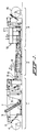
- the rotary screen printing installation consists of an intake section 1, a printing machine 2 and a take-off section 3.
- the intake section comprises a stock roll 4 of a substrate to be printed, which runs through the installation according to the web 5 in the direction of the arrow P.
- the web 5 runs from the stock roll 4 essentially via a wind-off roller 6 through a buffer 7, a pre-treatment installation 8 and a roller 9 via a curved surface 10 to the screen printing machine 2.
- the printing machine is provided with a number of parallel cylindrical stencils 12 rotatably bearing-mounted herein. In the embodiment shown, there are eight stencils, which each represent one print position. From the printing machine the web 5 then passes into the take-off section 3.
- This take-off section essentially comprises a drying installation 13, via which installation the web is wound, via tension adjusting devices and guide rollers, which are not described in more detail, on a stock roll 14.
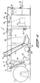
- FIG 2 the intake section 1 of the installation is shown on an enlarged scale and in more detail.
- the same parts are shown as far as possible with the same reference numbers as in Figure 1.
- Figure 2 again shows the stock roll 4 of the substrate to be printed, the substrate being wound off via the wind-off roller 6 located at the outer end of a swivelling lifting arm 15, which lifting arm is operated by a piston-cylinder assembly 16.
- the lifting arm 15, with the wind-off roller 6, rests against the stock roll 4.
- the wind-off roller 6, which is provided with a measuring device for the continuous measurement of the length of fabric passing over it, is driven by slip-free chain transmissions with the aid of a motor 17 and a reduction gear unit 18.
- the web 5 of the substrate to be printed then runs via a drive roller 19 into the buffer 7, which roller 19 is likewise driven by the motor 7 with a circumferential speed which is slightly greater that that of the wind-off roller 6.
- the web 5 runs taut through the buffer 7.
- the web then runs through a leveller 20 and a compensator or tension adjuster 21, which regulates the speed of the motor 17 depending on the tension of the fabric. From the compensator, the web 5 then runs to a fabric control device or stretcher 22.
- the web runs via the pretreatment installation 8 (for example for removing dust) to a drive roller 25, which is driven by a motor 23 and a reduction gear unit 24. From this drive roller 25, the web runs through a second compensator 26, which regulates the speed of the motor 23 depending on the tension of the fabric. Via this latter compensator, the web 5 is fed via the roller 9 over the curved surface 10, after which the web is fed into the printing machine 2.
- the intake section 1 of the rotary screen printing installation also contains a holder 27 for a roll 28 of a fabric of low quality, the so-called leader.
- this relatively inexpensive leader serves for setting the printing machine 2 so that, in this way, the loss of relatively expensive substrate as waste can be kept as small as possible.
- a sewing machine 29 is also provided for sewing the webs to one another when the stock roll is changed.
- the entire installation is filled with leader which extends from the roll 28 via guide rollers and the wind-off rollers 6 through the machine in accordance with the web 5 shown. If leader is fed into the installation from the roll 28, the lifting arm 15 is in the raised position shown in Figure 2. In this starting stage, the buffer 7 is filled with leader so that the web 5 is in loops in the buffer, as shown schematically in Figure 1.
- the length of the leader fed in depends on the number of print positions which are needed for carrying out the particular print order and is known from experience.
- the data for the print order now to be carried out i.e. the length of first quality, are entered into an electronic processing unit.
- the leader is then cut from the roll 28 and, with the aid of the sewing machine 29, the substrate from the stock roll 4 is firmly sewn to the trailing end of the leader fed into the installation.
- the printing machine 2 is now started at low speed, the printer setting the machine (bringing it into register) while this machine is using the low quality fabric stored in the buffer 7.
- the leveller 20 is reversed so that the fabric in front of the leveller, seen in the direction P of movement of the fabric, hangs slack, while beyond the leveller 20 the fabric is kept at tension as a consequence of the friction exerted on the fabric by the leveller.
- the leveller 20 can, for example, be controlled by a photoelectric cell which is fitted in the buffer and which records whether or not the buffer is filled. If the buffer is empty, the fabric runs taut through the buffer 7 and the leveller is set such that there is no difference in tension in the web over the leveller 20. In this situation the fabric is kept at tension by the compensator 26, which controls the drive motor 23.
- an acoustic signal is given by the processing unit.
- the printing speed is automatically brought back to a maximum of 40 m/min., or is kept constant if the printing speed is lower.
- the intake is now accelerated to a speed of about 100 m/min., so that the buffer is filled until the total number of meters of substrate to be printed for the particular order had been fed in. It will be clear that during this operation the leveller 20 is again reversed so that the fabric can be kept at tension beyond this leveller.
- the substrate is now cut at the intake and leader is sewn firmly to the trailing end of the substrate fed into the installation, this thus being carried out while the printing machine continues to run and uses substrate from the buffer.
- the leader is now fed in in synchronization with the speed of the printing machine.
- a signal is given to the processing unit, the precise number of meters of substrate fed in then being known.
- As much leader is fed into the buffer as is necessary to set the printing machine for carrying out the subsequent print order, which quantity is known from experience and is dependent on the number of print positions of the printing machine 2 which are to be used.
- the stockroll 4 with residual substrate can be removed and brought back to the stores, after which the installation is ready for carrying out the next print order.
- the quantity of substrate present on the stock roll is also measured, which can be effected, for example, via the angular position of the lifting arm 15 or by measuring the distance between the outer edge of the stock roll and the core of the roll. This value is also entered into the processing unit. If the quantity of substrate remaining on the roll after the print order is complete is less than a pre-determined minimum length, the residual portion of the substrate is automatically also printed until the entire roll has been used. The minimum residual stock which is still acceptable can be changed per print order and/or per roll. In this way it is avoided that a large number of rolls with too small a stock are left over.
- the processing unit establishes, via the measurement of the substrate stock, that this stock is less than 300 meters and the total print order is not yet complete with this, the intake is automatically accelerated to fill the buffer.
- the entire stock roll is rapidly fed in and the empty roll is then changed for the following roll and the new web is firmly sewn onto the trailing end of the substrate fed into the installation.
- the substrate from the new roll has been firmly sewn any substrate still present in the buffer is pulled through and the intake starts from the new stock roll, the substrate then again running taut through the buffer. In this way the stock roll can be changed without the printing machine having to be stopped.
- the warehouse stock control can also be automated.
Landscapes
- Engineering & Computer Science (AREA)
- Mechanical Engineering (AREA)
- Treatment Of Fiber Materials (AREA)
- Controlling Rewinding, Feeding, Winding, Or Abnormalities Of Webs (AREA)
- Screen Printers (AREA)
- Inking, Control Or Cleaning Of Printing Machines (AREA)
- Coloring (AREA)
Priority Applications (1)
| Application Number | Priority Date | Filing Date | Title |
|---|---|---|---|
| AT88202208T ATE67123T1 (de) | 1987-10-09 | 1988-10-04 | Verfahren zum steuern des durchgangs einer textilbahn durch eine rotationssiebdruckmaschine. |
Applications Claiming Priority (2)
| Application Number | Priority Date | Filing Date | Title |
|---|---|---|---|
| NL8702409 | 1987-10-09 | ||
| NL8702409A NL8702409A (nl) | 1987-10-09 | 1987-10-09 | Werkwijze voor het besturen van de doekdoorvoer in een rotatiezeefdrukinstallatie. |
Publications (2)
| Publication Number | Publication Date |
|---|---|
| EP0311211A1 true EP0311211A1 (de) | 1989-04-12 |
| EP0311211B1 EP0311211B1 (de) | 1991-09-11 |
Family
ID=19850731
Family Applications (1)
| Application Number | Title | Priority Date | Filing Date |
|---|---|---|---|
| EP88202208A Expired - Lifetime EP0311211B1 (de) | 1987-10-09 | 1988-10-04 | Verfahren zum Steuern des Durchgangs einer Textilbahn durch eine Rotationssiebdruckmaschine |
Country Status (6)
| Country | Link |
|---|---|
| US (1) | US4928585A (de) |
| EP (1) | EP0311211B1 (de) |
| JP (1) | JPH01133742A (de) |
| AT (1) | ATE67123T1 (de) |
| DE (1) | DE3864788D1 (de) |
| NL (1) | NL8702409A (de) |
Families Citing this family (2)
| Publication number | Priority date | Publication date | Assignee | Title |
|---|---|---|---|---|
| US5447680A (en) * | 1994-03-21 | 1995-09-05 | Mcdonnell Douglas Corporation | Fiber-reinforced, titanium based composites and method of forming without depletion zones |
| AR105863A1 (es) | 2015-08-31 | 2017-11-15 | Prec Planting Llc | Sistemas, métodos y aparatos para el control y monitoreo de implementos agrícolas multihileras |
Citations (1)
| Publication number | Priority date | Publication date | Assignee | Title |
|---|---|---|---|---|
| NL7301424A (de) * | 1972-02-08 | 1973-08-10 |
Family Cites Families (7)
| Publication number | Priority date | Publication date | Assignee | Title |
|---|---|---|---|---|
| US3292532A (en) * | 1964-05-01 | 1966-12-20 | J & C Carpet Company Inc | Apparatus and method for printing designs on web materials |
| GB1183177A (en) * | 1967-05-24 | 1970-03-04 | Vepa Ag | Process and Device for the Continuous Treatment of Textile Lengths |
| US3889595A (en) * | 1972-07-03 | 1975-06-17 | Precision Screen Machines | Continuous rotary screen printing method and apparatus |
| NL7315628A (nl) * | 1973-11-14 | 1975-05-16 | Stork Brabant Bv | Werkwijze en installatie voor het bedrukken van doeken. |
| US4101270A (en) * | 1975-06-20 | 1978-07-18 | Vepa Aktiengesellschaft | Process and apparatus for the continuous dyeing or printing of endless lengths of materials |
| JPS5584663A (en) * | 1978-12-20 | 1980-06-26 | Daiwa Spinning Co Ltd | Method and apparatus for automatic screen printing on towel material or the like |
| JPH0624843B2 (ja) * | 1984-02-02 | 1994-04-06 | 小松精練株式会社 | 自動スクリーン捺染装置 |
-
1987
- 1987-10-09 NL NL8702409A patent/NL8702409A/nl not_active Application Discontinuation
-
1988
- 1988-10-04 EP EP88202208A patent/EP0311211B1/de not_active Expired - Lifetime
- 1988-10-04 DE DE8888202208T patent/DE3864788D1/de not_active Expired - Fee Related
- 1988-10-04 AT AT88202208T patent/ATE67123T1/de not_active IP Right Cessation
- 1988-10-06 US US07/254,164 patent/US4928585A/en not_active Expired - Fee Related
- 1988-10-11 JP JP63256913A patent/JPH01133742A/ja active Pending
Patent Citations (1)
| Publication number | Priority date | Publication date | Assignee | Title |
|---|---|---|---|---|
| NL7301424A (de) * | 1972-02-08 | 1973-08-10 |
Also Published As
| Publication number | Publication date |
|---|---|
| NL8702409A (nl) | 1989-05-01 |
| DE3864788D1 (de) | 1991-10-17 |
| JPH01133742A (ja) | 1989-05-25 |
| ATE67123T1 (de) | 1991-09-15 |
| US4928585A (en) | 1990-05-29 |
| EP0311211B1 (de) | 1991-09-11 |
Similar Documents
| Publication | Publication Date | Title |
|---|---|---|
| US4077579A (en) | Edge alignment apparatus | |
| EP0454633B1 (de) | Aufrollvorrichtung mit Mitteln zur Änderung der Anzahl von Perforationen um jede Rolle während der Herstellung | |
| EP0101044B1 (de) | Verfahren und Vorrichtung zum Verbinden aufeinanderfolgender Bahnrollen zur Zufuhr zu einer Rotationspresse oder dergleichen | |
| RU2346822C2 (ru) | Машина с цифровым управлением для печати на тканях | |
| IT8948427A1 (it) | Procedimento ed apparecchiatura per accoppiare varie macchine per trattare materiali fotografici a nastro sensibili alla luce | |
| KR100511021B1 (ko) | 권취장치,특히슬리터-권취기에서제지웨브또는등가물의웨브와같은물질의쓰레딩방법및,이방법을실행하기위한장치 | |
| JP2617305B2 (ja) | 糸繰返し方法及び装置 | |
| US4614969A (en) | Process for manufacturing an endless tubular felt and apparatus for implementing the process | |
| CA2041372C (en) | Apparatus for changing the frequency of motion of a pusher | |
| GB2143215A (en) | Feeding webs | |
| JPS62130951A (ja) | ボビンを交換するための方法および装置並びにこの装置のための支承機構 | |
| JP2008056390A (ja) | 帯状体通し方法及びその装置 | |
| EP0166884A1 (de) | Verfahren und Vorrichtung zum Verbinden aufeinanderfolgender Papierbahnrollen | |
| US5229827A (en) | Image recording apparatus with sheet stackers | |
| GB2137964A (en) | Guiding Webs to Splicing Unit | |
| CA2328189A1 (en) | Method and apparatus for reeling a traveling paper web | |
| EP0311211B1 (de) | Verfahren zum Steuern des Durchgangs einer Textilbahn durch eine Rotationssiebdruckmaschine | |
| JP2637717B2 (ja) | 短尺経糸を製造する方法及び装置 | |
| FI75322B (fi) | Foerfarande och anordning foer att bilda lindningar i flera skikt av i fjaellformation ankommande plana, boejliga artiklar, foeretraedesvis tryckprodukter. | |
| EP0994975A1 (de) | Verfahren und vorrichtung zum schären mit einer konusschärmaschine | |
| JP2008056389A (ja) | 帯状体通し方法及びその装置 | |
| GB2044227A (en) | Centre-less winding | |
| US6533207B2 (en) | Method and arrangement for producing a roll from printed products | |
| DE69631401T2 (de) | Verfahren zum Vor- und Rückspulen photoempfindlichen Materials | |
| JPH0630949B2 (ja) | 製版原紙の着版装置 |
Legal Events
| Date | Code | Title | Description |
|---|---|---|---|
| PUAI | Public reference made under article 153(3) epc to a published international application that has entered the european phase |
Free format text: ORIGINAL CODE: 0009012 |
|
| AK | Designated contracting states |
Kind code of ref document: A1 Designated state(s): AT BE CH DE ES FR GB GR IT LI LU NL SE |
|
| 17P | Request for examination filed |
Effective date: 19890602 |
|
| 17Q | First examination report despatched |
Effective date: 19901030 |
|
| GRAA | (expected) grant |
Free format text: ORIGINAL CODE: 0009210 |
|
| STAA | Information on the status of an ep patent application or granted ep patent |
Free format text: STATUS: THE PATENT HAS BEEN GRANTED |
|
| AK | Designated contracting states |
Kind code of ref document: B1 Designated state(s): AT BE CH DE ES FR GB GR IT LI LU NL SE |
|
| PG25 | Lapsed in a contracting state [announced via postgrant information from national office to epo] |
Ref country code: ES Free format text: THE PATENT HAS BEEN ANNULLED BY A DECISION OF A NATIONAL AUTHORITY Effective date: 19910911 Ref country code: GR Free format text: LAPSE BECAUSE OF FAILURE TO SUBMIT A TRANSLATION OF THE DESCRIPTION OR TO PAY THE FEE WITHIN THE PRESCRIBED TIME-LIMIT Effective date: 19910911 Ref country code: SE Effective date: 19910911 Ref country code: BE Effective date: 19910911 |
|
| REF | Corresponds to: |
Ref document number: 67123 Country of ref document: AT Date of ref document: 19910915 Kind code of ref document: T |
|
| ITF | It: translation for a ep patent filed | ||
| REF | Corresponds to: |
Ref document number: 3864788 Country of ref document: DE Date of ref document: 19911017 |
|
| PG25 | Lapsed in a contracting state [announced via postgrant information from national office to epo] |
Ref country code: LU Free format text: LAPSE BECAUSE OF NON-PAYMENT OF DUE FEES Effective date: 19911031 |
|
| EN | Fr: translation not filed | ||
| PG25 | Lapsed in a contracting state [announced via postgrant information from national office to epo] |
Ref country code: FR Effective date: 19920131 |
|
| PLBI | Opposition filed |
Free format text: ORIGINAL CODE: 0009260 |
|
| 26 | Opposition filed |
Opponent name: ZIMMER, JOHANNES Effective date: 19920611 |
|
| NLR1 | Nl: opposition has been filed with the epo |
Opponent name: ZIMMER, JOHANNES. |
|
| PG25 | Lapsed in a contracting state [announced via postgrant information from national office to epo] |
Ref country code: GB Effective date: 19921004 |
|
| REG | Reference to a national code |
Ref country code: FR Ref legal event code: ST |
|
| GBPC | Gb: european patent ceased through non-payment of renewal fee |
Effective date: 19921004 |
|
| PLBJ | Opposition found inadmissible |
Free format text: ORIGINAL CODE: 0009275 |
|
| 26U | Opposition found inadmissible | ||
| NLXE | Nl: other communications concerning ep-patents (part 3 heading xe) |
Free format text: PAT.BUL.19/92 OPPOSITION 01 HAS BEEN DECLARED INADMISSABLE |
|
| PGFP | Annual fee paid to national office [announced via postgrant information from national office to epo] |
Ref country code: CH Payment date: 19960919 Year of fee payment: 9 |
|
| PGFP | Annual fee paid to national office [announced via postgrant information from national office to epo] |
Ref country code: AT Payment date: 19961028 Year of fee payment: 9 |
|
| PGFP | Annual fee paid to national office [announced via postgrant information from national office to epo] |
Ref country code: NL Payment date: 19961031 Year of fee payment: 9 |
|
| PGFP | Annual fee paid to national office [announced via postgrant information from national office to epo] |
Ref country code: DE Payment date: 19961230 Year of fee payment: 9 |
|
| PG25 | Lapsed in a contracting state [announced via postgrant information from national office to epo] |
Ref country code: AT Free format text: LAPSE BECAUSE OF NON-PAYMENT OF DUE FEES Effective date: 19971004 |
|
| PG25 | Lapsed in a contracting state [announced via postgrant information from national office to epo] |
Ref country code: LI Free format text: LAPSE BECAUSE OF NON-PAYMENT OF DUE FEES Effective date: 19971031 Ref country code: CH Free format text: LAPSE BECAUSE OF NON-PAYMENT OF DUE FEES Effective date: 19971031 |
|
| PG25 | Lapsed in a contracting state [announced via postgrant information from national office to epo] |
Ref country code: NL Free format text: LAPSE BECAUSE OF NON-PAYMENT OF DUE FEES Effective date: 19980501 |
|
| REG | Reference to a national code |
Ref country code: CH Ref legal event code: PL |
|
| NLV4 | Nl: lapsed or anulled due to non-payment of the annual fee |
Effective date: 19980501 |
|
| PG25 | Lapsed in a contracting state [announced via postgrant information from national office to epo] |
Ref country code: DE Free format text: LAPSE BECAUSE OF NON-PAYMENT OF DUE FEES Effective date: 19980701 |
|
| PG25 | Lapsed in a contracting state [announced via postgrant information from national office to epo] |
Ref country code: IT Free format text: LAPSE BECAUSE OF NON-PAYMENT OF DUE FEES;WARNING: LAPSES OF ITALIAN PATENTS WITH EFFECTIVE DATE BEFORE 2007 MAY HAVE OCCURRED AT ANY TIME BEFORE 2007. THE CORRECT EFFECTIVE DATE MAY BE DIFFERENT FROM THE ONE RECORDED. Effective date: 20051004 |
|
| PLAB | Opposition data, opponent's data or that of the opponent's representative modified |
Free format text: ORIGINAL CODE: 0009299OPPO |
|
| R26U | Opposition found inadmissible (corrected) |
Opponent name: ZIMMER, JOHANNES Effective date: 19931012 |