EP0311317A2 - Verbrennungsverfahren für spezifische Abgase mit schädlichen Stoffen - Google Patents
Verbrennungsverfahren für spezifische Abgase mit schädlichen Stoffen Download PDFInfo
- Publication number
- EP0311317A2 EP0311317A2 EP88309126A EP88309126A EP0311317A2 EP 0311317 A2 EP0311317 A2 EP 0311317A2 EP 88309126 A EP88309126 A EP 88309126A EP 88309126 A EP88309126 A EP 88309126A EP 0311317 A2 EP0311317 A2 EP 0311317A2
- Authority
- EP
- European Patent Office
- Prior art keywords
- exhaust gases
- combustion
- nozzle
- top end
- flame
- Prior art date
- Legal status (The legal status is an assumption and is not a legal conclusion. Google has not performed a legal analysis and makes no representation as to the accuracy of the status listed.)
- Withdrawn
Links
- 239000007789 gas Substances 0.000 title claims abstract description 93
- 239000000126 substance Substances 0.000 title claims description 21
- 230000002939 deleterious effect Effects 0.000 title claims description 20
- 238000009841 combustion method Methods 0.000 title description 6
- 238000002485 combustion reaction Methods 0.000 claims abstract description 56
- 230000004888 barrier function Effects 0.000 claims abstract description 28
- 238000000034 method Methods 0.000 claims abstract description 14
- 238000006243 chemical reaction Methods 0.000 claims abstract description 13
- 239000011261 inert gas Substances 0.000 claims description 12
- BLRPTPMANUNPDV-UHFFFAOYSA-N Silane Chemical compound [SiH4] BLRPTPMANUNPDV-UHFFFAOYSA-N 0.000 abstract description 20
- 229910000077 silane Inorganic materials 0.000 abstract description 19
- QGZKDVFQNNGYKY-UHFFFAOYSA-N Ammonia Chemical compound N QGZKDVFQNNGYKY-UHFFFAOYSA-N 0.000 description 10
- IJGRMHOSHXDMSA-UHFFFAOYSA-N Atomic nitrogen Chemical compound N#N IJGRMHOSHXDMSA-UHFFFAOYSA-N 0.000 description 8
- 238000000151 deposition Methods 0.000 description 8
- 230000008021 deposition Effects 0.000 description 7
- 230000000694 effects Effects 0.000 description 7
- RBFQJDQYXXHULB-UHFFFAOYSA-N arsane Chemical compound [AsH3] RBFQJDQYXXHULB-UHFFFAOYSA-N 0.000 description 5
- 238000000354 decomposition reaction Methods 0.000 description 5
- ATUOYWHBWRKTHZ-UHFFFAOYSA-N Propane Chemical compound CCC ATUOYWHBWRKTHZ-UHFFFAOYSA-N 0.000 description 4
- 229910001873 dinitrogen Inorganic materials 0.000 description 4
- VNWKTOKETHGBQD-UHFFFAOYSA-N methane Chemical compound C VNWKTOKETHGBQD-UHFFFAOYSA-N 0.000 description 4
- RWSOTUBLDIXVET-UHFFFAOYSA-N Dihydrogen sulfide Chemical compound S RWSOTUBLDIXVET-UHFFFAOYSA-N 0.000 description 3
- 229910021529 ammonia Inorganic materials 0.000 description 3
- 239000000945 filler Substances 0.000 description 3
- 229910000078 germane Inorganic materials 0.000 description 3
- UFHFLCQGNIYNRP-UHFFFAOYSA-N Hydrogen Chemical compound [H][H] UFHFLCQGNIYNRP-UHFFFAOYSA-N 0.000 description 2
- XYFCBTPGUUZFHI-UHFFFAOYSA-N Phosphine Chemical compound P XYFCBTPGUUZFHI-UHFFFAOYSA-N 0.000 description 2
- BUGBHKTXTAQXES-UHFFFAOYSA-N Selenium Chemical compound [Se] BUGBHKTXTAQXES-UHFFFAOYSA-N 0.000 description 2
- 229910000070 arsenic hydride Inorganic materials 0.000 description 2
- QVGXLLKOCUKJST-UHFFFAOYSA-N atomic oxygen Chemical compound [O] QVGXLLKOCUKJST-UHFFFAOYSA-N 0.000 description 2
- QUZPNFFHZPRKJD-UHFFFAOYSA-N germane Chemical compound [GeH4] QUZPNFFHZPRKJD-UHFFFAOYSA-N 0.000 description 2
- 229910052986 germanium hydride Inorganic materials 0.000 description 2
- 239000001257 hydrogen Substances 0.000 description 2
- 229910052739 hydrogen Inorganic materials 0.000 description 2
- 238000002156 mixing Methods 0.000 description 2
- 239000003345 natural gas Substances 0.000 description 2
- 229910052757 nitrogen Inorganic materials 0.000 description 2
- 229910000069 nitrogen hydride Inorganic materials 0.000 description 2
- 230000001473 noxious effect Effects 0.000 description 2
- 230000003647 oxidation Effects 0.000 description 2
- 238000007254 oxidation reaction Methods 0.000 description 2
- 239000001301 oxygen Substances 0.000 description 2
- 229910052760 oxygen Inorganic materials 0.000 description 2
- 239000001294 propane Substances 0.000 description 2
- 238000004891 communication Methods 0.000 description 1
- 230000000052 comparative effect Effects 0.000 description 1
- 238000007796 conventional method Methods 0.000 description 1
- 238000007865 diluting Methods 0.000 description 1
- 238000010790 dilution Methods 0.000 description 1
- 239000012895 dilution Substances 0.000 description 1
- 238000007599 discharging Methods 0.000 description 1
- PZPGRFITIJYNEJ-UHFFFAOYSA-N disilane Chemical compound [SiH3][SiH3] PZPGRFITIJYNEJ-UHFFFAOYSA-N 0.000 description 1
- 238000004817 gas chromatography Methods 0.000 description 1
- 238000010438 heat treatment Methods 0.000 description 1
- 229910000037 hydrogen sulfide Inorganic materials 0.000 description 1
- 239000004615 ingredient Substances 0.000 description 1
- 230000004807 localization Effects 0.000 description 1
- 238000004519 manufacturing process Methods 0.000 description 1
- 239000000463 material Substances 0.000 description 1
- 239000002184 metal Substances 0.000 description 1
- 229910000073 phosphorus hydride Inorganic materials 0.000 description 1
- 238000005201 scrubbing Methods 0.000 description 1
- SPVXKVOXSXTJOY-UHFFFAOYSA-N selane Chemical compound [SeH2] SPVXKVOXSXTJOY-UHFFFAOYSA-N 0.000 description 1
- 229910000058 selane Inorganic materials 0.000 description 1
- 239000004065 semiconductor Substances 0.000 description 1
- 231100000331 toxic Toxicity 0.000 description 1
- 230000002588 toxic effect Effects 0.000 description 1
- 231100000419 toxicity Toxicity 0.000 description 1
- 230000001988 toxicity Effects 0.000 description 1
Images

Classifications
-
- F—MECHANICAL ENGINEERING; LIGHTING; HEATING; WEAPONS; BLASTING
- F23—COMBUSTION APPARATUS; COMBUSTION PROCESSES
- F23G—CREMATION FURNACES; CONSUMING WASTE PRODUCTS BY COMBUSTION
- F23G7/00—Incinerators or other apparatus for consuming industrial waste, e.g. chemicals
- F23G7/06—Incinerators or other apparatus for consuming industrial waste, e.g. chemicals of waste gases or noxious gases, e.g. exhaust gases
- F23G7/061—Incinerators or other apparatus for consuming industrial waste, e.g. chemicals of waste gases or noxious gases, e.g. exhaust gases with supplementary heating
- F23G7/065—Incinerators or other apparatus for consuming industrial waste, e.g. chemicals of waste gases or noxious gases, e.g. exhaust gases with supplementary heating using gaseous or liquid fuel
-
- F—MECHANICAL ENGINEERING; LIGHTING; HEATING; WEAPONS; BLASTING
- F23—COMBUSTION APPARATUS; COMBUSTION PROCESSES
- F23G—CREMATION FURNACES; CONSUMING WASTE PRODUCTS BY COMBUSTION
- F23G2209/00—Specific waste
- F23G2209/14—Gaseous waste or fumes
- F23G2209/142—Halogen gases, e.g. silane
Definitions
- the present invention concerns a method for combustion of exhaust gases containing deleterious substances such as silane exhausted from reaction furnaces, etc.
- Exhaust gases discharged from reaction furnaces in various plants such as semiconductor production plants contain deleterious substances which are highly toxic and likely to cause pyrophoric danger in contact with air, such as silane (SIH4), disalane (Si2H6), phospine (PH3), arsine (AsH3), germane (GeH4), ammonia (NH3), hydrogen selenide (H2Se), hydrogen sulfide (H2S).
- silane Si2H6
- PH3 phospine
- AsH3 arsine
- GeH4 germane
- NH3 ammonia
- H2Se hydrogen selenide
- H2S hydrogen sulfide
- US-A-4,555,389 discloses a method of supplying an inert gas such as a nitrogen gas near the top end of the exhaust gas nozzle thereby forming an inert gas atmosphere, and burning the exhaust gases ahead of this atmosphere, thereby preventing the deposition of combustion oxides at the top end of the nozzle.
- an inert gas such as a nitrogen gas near the top end of the exhaust gas nozzle thereby forming an inert gas atmosphere
- burning the exhaust gases ahead of this atmosphere thereby preventing the deposition of combustion oxides at the top end of the nozzle.
- Another object of the present invention is to provide a combustion method for exhaust gases capable of attaining the above-mentioned purpose for exhaust gases containing a wide range of deleterious substances such as silane, disilane, phosphine, arsine, germane, ammonia, hydrogen selenide, hydrogen sulfide.
- the method of the invention is capable of maintaining a high decomposition rate upon combustion even when the concentration of the noxious substances is low and is also capable of preventing the deposition of oxides at the top end of the combustion nozzle.
- Deleterious substance that are contained in specific exhaust gases discharged from reaction furnaces from various plants and which can be disposed of by combustion include for example silane (SiH4), disalane (Si2H6), phospine (PH3), arsine (AsH3), germane (GeH4), ammonia (NH3), hydrogen selenide (H2Se) and hydrogen sulfide (H2S).
- the present inventors have made an earnest study of methods of burning the specific exhaust gases containing these deleterious substances by reaction with air in a combustion chamber and then applying after treatment in a scrubber, a bag filter, etc., to solve the problem of the deposition of oxides on an exhaust gas nozzle and, in addition, to dispose of these substances at a high rate of decomposition upon combustion over a range of various deleterious substances irrespective of their concentration.
- the flame barrier of the combustible gas formed around the top end of the exhaust gas nozzle consumes oxygen upon combustion around the top end of the nozzle to suppress the combustion of the exhaust gases at the top end of the nozzle, as well as to heat the exhaust gases as they pass through the flame barrier and burns the gases discharged ahead of the flame barrier, i.e., into air.
- the flame barrier in the present invention can provide both the effect of preventing the combustion of the exhaust gases at the top end of the nozzle and the effect of forcibly burning the exhaust gases ahead of the flame barrier, which can both prevent the deposition of oxides at the top end of the exhaust gas nozzle and provide improvements in the combustion efficiency.
- the specific exhaust gases containing deleterious substances may, preferably, be mixed with inert gas such as a nitrogen gas and previously diluted to a desired concentration before combustion treatment.
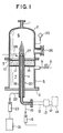
- the combustion device comprises a vertical cylindrical body 4 closed at the upper and the lower ends thereof by an upper member 2 having a discharge port 1 and a lower plate 3 respectively.
- the cylindrical body 4 is vertically partitioned at the intermediate its ends with a perforated plate 5 to constitute a combustion cylinder having a combustion chamber 6 in the upper portion and an air chamber 7 in the lower portion.
- the air chamber 7 is connected with an air supply pipe 9 having a solenoid valve 8.
- the air chamber 7 formed below the combustion chamber 6 is in communication with the combustion chamber 6 by way of apertures 19 in the perforated plate 5 thereby constituting an air supply section to the combustion chamber 6.
- An exhaust gas introduction pipe 11 is inserted from below the air chamber 7 in the axial direction of the cylindrical body 4 and the pipe 11 is disposed such that it penetrates the lower plate 3 and the perforated plate 5 and a top end nozzle thereof protrudes inside of the combustion chamber 6.
- the rear end of the exhaust gas introduction pipe 11 is conected by way of an exhaust gas pipe 12 with a gas supply section 13 for receiving specific exhaust gases from a reaction furnace 14 that contains silane gas, etc.
- the exhaust gas introduction pipe 11 is also connected with an inert gas mixing pipe 15, such that an inert gas is mixed into the exhaust gases in the exhaust gas introduction pipe 11 to dilute the exhaust gases.
- a flow rate controller 16 is disposed in the inert gas mixing pipe 15 so that the concentration and the flow rate of the exhaust gases jetted out from the top end nozzle of the exhaust gas introduction pipe 11 are controlled.
- the boundary between the combustion chamber 6 and the air chamber 7 is constituted only by the perforated plate 5, it may cause the localization of air flow from the air chamber 7 to the combustion chamber 6 to a specific position, or may cause a backfire danger in which the flame in the combustion chamber 6 enters into the air chamber 7.
- a porous filler layer 17 made of non-combustible but air-permeable material of an appropriate thickness is applied to the lower surface of the perforated plate 5.
- a metal gage or a lattice-like support member 18 is fitted to the lower surface of the filler layer 17 so that the filler does not fall.
- an outer pipe 19 is provided passing through the lower plate 3 and the perforated plate 5 of the air chamber 7 in the same manner as the exhaust gas introduction pipe 11 and spaced from the outer periphery of the exhaust gas introduction pipe 11 substantially in a coaxial manner to constitute a double-walled tubular combustion nozzle 20.
- a pipe 22 connected with a source 21 of combustible gas such as propane, natural gas or hydrogen is connected to the rear end of the outer pipe 19 by way of a flow rate controller 23 such that the flow rate and the flow speed of the combustible gas jetted out from the top end of the nozzle of the outer pipe 19 may be controlled.
- a view window 26 is disposed in the combustion chamber 6 so that the state of the inside, particularly state of the flame generated above the nozzle of the exhaust gas introduction pipe 11 and the outer pipe 19, can be observed.
- a pressure gauge 25 is fitted to the combustion chamber 6.
- An automatic ignition device 28 is preferably disposed near the upper jetting portion 27 of the double-walled tubular combustion nozzle 20 for the combustion of the combustible gases supplied from the outer tube 19.
- the combustible gas is supplied from the outer pipe 19 and burnt by the nozzle of the outer pipe 19 to form a flame barrier composed of the combustible gas around the top end of the nozzle of the exhaust gas introduction pipe 11.
- exhaust gas containing deleterious substances such as silane, etc. sent from the reaction furnace are supplied, after dilution, by way of the exhaust gas introduction pipe 11 and jetted out from the top end nozzle thereof passing through the inside of the flame barrier into the combustion chamber 6.
- the exhaust gases pass through the flame barrier without combustion since the periphery around the top end of the nozzle of the exhaust gas introduction pipe 11 is surrounded with the flame barrier of the combustible gas and oxygen required for the combustion of the exhaust gases is insufficient there and also due to the effect of the flow rate of the flame.
- FIG 2 shows the combustion method as disclosed in US-A-4,555,389 for the combustion of exhaust gases, by using the combustion device shown in Figure 1.
- an inert gas barrier is formed at the top end of a double-walled tubular combustion nozzle 20 by supplying an inert gas (for example, nitrogen) from an outer pipe 19 and, at the same time, diluted silane-containing exhaust gases are supplied in the same manner as the present invention from an exhaust gas introduction pipe 11, passed through the inside of and burnt ahead of the inert gas barrier.
- an inert gas for example, nitrogen
- Combustion processing data for the silane-containing exhaust gases are shown below in comparison between the present invention and conventional examples.
- silane when using the prior art inert gas curtain (nitrogen), silane is not burnt at all if the silane concentration is less than 0.33%, and the combustion ratio of silane can not attain 100% even at a silane concentration as high as 2.9%.
- complete combustion takes place according to the present invention even if the silane concentration is as low as 0.16% in exhaust gases.
- the flame barrier can provide both the effect of preventing the deposition of oxides and the effect of improving the combustion ratio, the structure of the device is not complicated and the existing device used for the conventional method can be utilized as it is.
Landscapes
- Engineering & Computer Science (AREA)
- Environmental & Geological Engineering (AREA)
- Mechanical Engineering (AREA)
- General Engineering & Computer Science (AREA)
- Incineration Of Waste (AREA)
Applications Claiming Priority (2)
| Application Number | Priority Date | Filing Date | Title |
|---|---|---|---|
| JP25226287A JPH0195214A (ja) | 1987-10-06 | 1987-10-06 | 特殊材料ガスの燃焼方法 |
| JP252262/87 | 1987-10-06 |
Publications (2)
| Publication Number | Publication Date |
|---|---|
| EP0311317A2 true EP0311317A2 (de) | 1989-04-12 |
| EP0311317A3 EP0311317A3 (de) | 1990-03-28 |
Family
ID=17234785
Family Applications (1)
| Application Number | Title | Priority Date | Filing Date |
|---|---|---|---|
| EP88309126A Withdrawn EP0311317A3 (de) | 1987-10-06 | 1988-09-30 | Verbrennungsverfahren für spezifische Abgase mit schädlichen Stoffen |
Country Status (2)
| Country | Link |
|---|---|
| EP (1) | EP0311317A3 (de) |
| JP (1) | JPH0195214A (de) |
Cited By (7)
| Publication number | Priority date | Publication date | Assignee | Title |
|---|---|---|---|---|
| EP0694735A1 (de) * | 1994-07-25 | 1996-01-31 | Alzeta Corporation | Zerstörung giftiger Substanzen durch Verbrennung |
| EP0735321A3 (de) * | 1995-03-30 | 1997-03-26 | Das Duennschicht Anlagen Sys | Verfahren und Einrichtung zur Reinigung von schadstoffhaltigen Abgasen durch chemische Umsetzung |
| EP0802370A3 (de) * | 1996-04-16 | 1997-12-10 | The BOC Group plc | Entsorgung schädlicher Substanzen aus Gasströmen |
| WO2006117531A1 (en) * | 2005-05-05 | 2006-11-09 | Edwards Limited | Gas combustion apparatus |
| WO2006123092A1 (en) * | 2005-05-16 | 2006-11-23 | Edwards Limited | Gas combustion apparatus |
| CN103471108A (zh) * | 2013-07-22 | 2013-12-25 | 北京航天动力研究所 | 笑气焚烧燃烧器 |
| WO2022171383A1 (de) * | 2021-02-12 | 2022-08-18 | Das Environmental Expert Gmbh | Verfahren und brenner zur thermischen entsorgung von schadstoffen in prozessgasen |
Families Citing this family (2)
| Publication number | Priority date | Publication date | Assignee | Title |
|---|---|---|---|---|
| US6017611A (en) * | 1998-02-20 | 2000-01-25 | Felix Schoeller Technical Papers, Inc. | Ink jet printable support material for thermal transfer |
| JP7027817B2 (ja) * | 2017-11-02 | 2022-03-02 | 株式会社Ihi | 燃焼装置及びボイラ |
Family Cites Families (7)
| Publication number | Priority date | Publication date | Assignee | Title |
|---|---|---|---|---|
| BE508951A (de) * | 1951-02-07 | |||
| US3365274A (en) * | 1964-07-13 | 1968-01-23 | Cabot Corp | Metal and metalloid oxide production |
| DE2241891C3 (de) * | 1972-08-25 | 1980-04-03 | Didier-Engineering Gmbh, 4300 Essen | Verfahren und Vorrichtung zur Verbrennung von bei der Reinigung von Koksofengasen anfallenden Ammoniakschwaden |
| JPS5984019A (ja) * | 1982-11-05 | 1984-05-15 | Toyo Sanso Kk | 排ガス処理におけるモノ・シランガス燃焼方法 |
| US4555389A (en) * | 1984-04-27 | 1985-11-26 | Toyo Sanso Co., Ltd. | Method of and apparatus for burning exhaust gases containing gaseous silane |
| JPS6387519A (ja) * | 1986-09-29 | 1988-04-18 | Mitsubishi Jushi Eng Kk | 半導体製造装置の排ガス燃焼方法 |
| FR2612606B1 (fr) * | 1987-03-18 | 1990-09-14 | Air Liquide | Procede et dispositif de destruction d'effluents gazeux toxiques |
-
1987
- 1987-10-06 JP JP25226287A patent/JPH0195214A/ja active Pending
-
1988
- 1988-09-30 EP EP88309126A patent/EP0311317A3/de not_active Withdrawn
Cited By (16)
| Publication number | Priority date | Publication date | Assignee | Title |
|---|---|---|---|---|
| EP0694735A1 (de) * | 1994-07-25 | 1996-01-31 | Alzeta Corporation | Zerstörung giftiger Substanzen durch Verbrennung |
| EP0735321A3 (de) * | 1995-03-30 | 1997-03-26 | Das Duennschicht Anlagen Sys | Verfahren und Einrichtung zur Reinigung von schadstoffhaltigen Abgasen durch chemische Umsetzung |
| EP0802370A3 (de) * | 1996-04-16 | 1997-12-10 | The BOC Group plc | Entsorgung schädlicher Substanzen aus Gasströmen |
| WO2006117531A1 (en) * | 2005-05-05 | 2006-11-09 | Edwards Limited | Gas combustion apparatus |
| CN101171455B (zh) * | 2005-05-05 | 2012-05-09 | 爱德华兹有限公司 | 气体燃烧设备 |
| TWI391611B (zh) * | 2005-05-05 | 2013-04-01 | Edwards Ltd | 氣體燃燒裝置 |
| US8647111B2 (en) | 2005-05-05 | 2014-02-11 | Edwards Limited | Gas combustion apparatus |
| US8662883B2 (en) | 2005-05-16 | 2014-03-04 | Edwards Limited | Gas combustion apparatus |
| WO2006123092A1 (en) * | 2005-05-16 | 2006-11-23 | Edwards Limited | Gas combustion apparatus |
| CN101175949B (zh) * | 2005-05-16 | 2011-08-31 | 爱德华兹有限公司 | 燃烧废气的设备和方法 |
| CN103471108A (zh) * | 2013-07-22 | 2013-12-25 | 北京航天动力研究所 | 笑气焚烧燃烧器 |
| CN103471108B (zh) * | 2013-07-22 | 2016-08-31 | 北京航天动力研究所 | 笑气焚烧燃烧器 |
| WO2022171383A1 (de) * | 2021-02-12 | 2022-08-18 | Das Environmental Expert Gmbh | Verfahren und brenner zur thermischen entsorgung von schadstoffen in prozessgasen |
| CN115210502A (zh) * | 2021-02-12 | 2022-10-18 | 达斯环境专家有限责任公司 | 用于热清除工艺气体中的有害物质的方法和燃烧器 |
| CN115210502B (zh) * | 2021-02-12 | 2025-02-18 | 达斯环境专家有限责任公司 | 用于热清除工艺气体中的有害物质的方法和燃烧器 |
| US12601479B2 (en) | 2021-02-12 | 2026-04-14 | Das Environmental Expert Gmbh | Process and burner for the thermal disposal of pollutants in process gases |
Also Published As
| Publication number | Publication date |
|---|---|
| EP0311317A3 (de) | 1990-03-28 |
| JPH0195214A (ja) | 1989-04-13 |
Similar Documents
| Publication | Publication Date | Title |
|---|---|---|
| US4555389A (en) | Method of and apparatus for burning exhaust gases containing gaseous silane | |
| DE69520313T2 (de) | Zerstörung giftiger Substanzen durch Verbrennung | |
| JP3467275B2 (ja) | 排ガス浄化装置 | |
| DE69615303T2 (de) | Vorrichtung und Verfahren zur Abgasreinigung | |
| EP0311317A2 (de) | Verbrennungsverfahren für spezifische Abgase mit schädlichen Stoffen | |
| KR101887248B1 (ko) | 연소 제해 장치 | |
| EP0754908A3 (de) | Verfahren und Vorrichtung zur Unterdrückung von Flammen-/Druckschwingungen bei einer Feuerung | |
| DE69600429T2 (de) | Verfahren zum Schmelzen von Verbrennungsaschen | |
| US20030152882A1 (en) | Burner for decomposing nonflammable materials | |
| JPH0268414A (ja) | 有毒性ガスの燃焼処理法及び装置 | |
| TWI271491B (en) | Burner and process for combustion of a gas capable of reacting to form solid products | |
| US4144313A (en) | Method of purifying gases by combustion | |
| JPS62134414A (ja) | 半導体製造排ガスの燃焼方法及び同燃焼装置 | |
| JP2881210B2 (ja) | 有毒性排ガスの処理方法及び装置 | |
| JPH0344993Y2 (de) | ||
| JP2742562B2 (ja) | 有毒性排ガスの燃焼処理方法 | |
| JP3453012B2 (ja) | 排ガス処理用燃焼ノズル | |
| EP1414549B1 (de) | Anordnung und verfahren zur reinigung von abgasen | |
| JPH02126014A (ja) | 有毒性ガスの燃焼処理方法及び装置 | |
| CA2397917C (en) | Treatment plant for refuse derived fuels | |
| JP2745074B2 (ja) | 逆火防止装置及びこれを含む排ガス燃焼処理装置 | |
| JP2008292077A (ja) | 排ガスの浄化装置 | |
| JP3993686B2 (ja) | 排ガス除害装置 | |
| JP2688658B2 (ja) | 排ガス熱焼処理装置における逆火防止装置 | |
| KR0170717B1 (ko) | 이중 배관의 배기 가스 유입관을 갖는 가스 스크러버 |
Legal Events
| Date | Code | Title | Description |
|---|---|---|---|
| PUAI | Public reference made under article 153(3) epc to a published international application that has entered the european phase |
Free format text: ORIGINAL CODE: 0009012 |
|
| AK | Designated contracting states |
Kind code of ref document: A2 Designated state(s): BE CH DE FR GB IT LI NL |
|
| PUAL | Search report despatched |
Free format text: ORIGINAL CODE: 0009013 |
|
| AK | Designated contracting states |
Kind code of ref document: A3 Designated state(s): BE CH DE FR GB IT LI NL |
|
| STAA | Information on the status of an ep patent application or granted ep patent |
Free format text: STATUS: THE APPLICATION IS DEEMED TO BE WITHDRAWN |
|
| 18D | Application deemed to be withdrawn |
Effective date: 19900929 |