EP0311478B1 - Vérin à vis à sécurité de surcharge pour élément déplaçable, tel qu'un siège - Google Patents
Vérin à vis à sécurité de surcharge pour élément déplaçable, tel qu'un siège Download PDFInfo
- Publication number
- EP0311478B1 EP0311478B1 EP88402412A EP88402412A EP0311478B1 EP 0311478 B1 EP0311478 B1 EP 0311478B1 EP 88402412 A EP88402412 A EP 88402412A EP 88402412 A EP88402412 A EP 88402412A EP 0311478 B1 EP0311478 B1 EP 0311478B1
- Authority
- EP
- European Patent Office
- Prior art keywords
- nut
- screw
- jack
- screw thread
- seat
- Prior art date
- Legal status (The legal status is an assumption and is not a legal conclusion. Google has not performed a legal analysis and makes no representation as to the accuracy of the status listed.)
- Expired - Lifetime
Links
- 239000000463 material Substances 0.000 claims description 11
- 229920003023 plastic Polymers 0.000 claims description 8
- 239000004033 plastic Substances 0.000 claims description 8
- 239000002131 composite material Substances 0.000 claims description 5
- 239000011295 pitch Substances 0.000 description 3
- 229910000831 Steel Inorganic materials 0.000 description 2
- 239000010959 steel Substances 0.000 description 2
- 229930182556 Polyacetal Natural products 0.000 description 1
- 230000000694 effects Effects 0.000 description 1
- 229920006324 polyoxymethylene Polymers 0.000 description 1
- 230000035939 shock Effects 0.000 description 1
- 238000003466 welding Methods 0.000 description 1
Images


Classifications
-
- B—PERFORMING OPERATIONS; TRANSPORTING
- B60—VEHICLES IN GENERAL
- B60N—SEATS SPECIALLY ADAPTED FOR VEHICLES; VEHICLE PASSENGER ACCOMMODATION NOT OTHERWISE PROVIDED FOR
- B60N2/00—Seats specially adapted for vehicles; Arrangement or mounting of seats in vehicles
- B60N2/02—Seats specially adapted for vehicles; Arrangement or mounting of seats in vehicles the seat or part thereof being movable, e.g. adjustable
- B60N2/04—Seats specially adapted for vehicles; Arrangement or mounting of seats in vehicles the seat or part thereof being movable, e.g. adjustable the whole seat being movable
- B60N2/06—Seats specially adapted for vehicles; Arrangement or mounting of seats in vehicles the seat or part thereof being movable, e.g. adjustable the whole seat being movable slidable
- B60N2/067—Seats specially adapted for vehicles; Arrangement or mounting of seats in vehicles the seat or part thereof being movable, e.g. adjustable the whole seat being movable slidable by linear actuators, e.g. linear screw mechanisms
-
- B—PERFORMING OPERATIONS; TRANSPORTING
- B60—VEHICLES IN GENERAL
- B60N—SEATS SPECIALLY ADAPTED FOR VEHICLES; VEHICLE PASSENGER ACCOMMODATION NOT OTHERWISE PROVIDED FOR
- B60N2/00—Seats specially adapted for vehicles; Arrangement or mounting of seats in vehicles
- B60N2/02—Seats specially adapted for vehicles; Arrangement or mounting of seats in vehicles the seat or part thereof being movable, e.g. adjustable
- B60N2/04—Seats specially adapted for vehicles; Arrangement or mounting of seats in vehicles the seat or part thereof being movable, e.g. adjustable the whole seat being movable
- B60N2/06—Seats specially adapted for vehicles; Arrangement or mounting of seats in vehicles the seat or part thereof being movable, e.g. adjustable the whole seat being movable slidable
- B60N2/07—Slide construction
- B60N2/0722—Constructive details
- B60N2/0732—Attachment of seat frame to the slide, e.g. eyelets
-
- F—MECHANICAL ENGINEERING; LIGHTING; HEATING; WEAPONS; BLASTING
- F16—ENGINEERING ELEMENTS AND UNITS; GENERAL MEASURES FOR PRODUCING AND MAINTAINING EFFECTIVE FUNCTIONING OF MACHINES OR INSTALLATIONS; THERMAL INSULATION IN GENERAL
- F16H—GEARING
- F16H25/00—Gearings comprising primarily only cams, cam-followers and screw-and-nut mechanisms
- F16H25/18—Gearings comprising primarily only cams, cam-followers and screw-and-nut mechanisms for conveying or interconverting oscillating or reciprocating motions
- F16H25/20—Screw mechanisms
- F16H25/24—Elements essential to such mechanisms, e.g. screws, nuts
- F16H25/2472—Safety nuts
-
- Y—GENERAL TAGGING OF NEW TECHNOLOGICAL DEVELOPMENTS; GENERAL TAGGING OF CROSS-SECTIONAL TECHNOLOGIES SPANNING OVER SEVERAL SECTIONS OF THE IPC; TECHNICAL SUBJECTS COVERED BY FORMER USPC CROSS-REFERENCE ART COLLECTIONS [XRACs] AND DIGESTS
- Y10—TECHNICAL SUBJECTS COVERED BY FORMER USPC
- Y10T—TECHNICAL SUBJECTS COVERED BY FORMER US CLASSIFICATION
- Y10T74/00—Machine element or mechanism
- Y10T74/18—Mechanical movements
- Y10T74/18568—Reciprocating or oscillating to or from alternating rotary
- Y10T74/18576—Reciprocating or oscillating to or from alternating rotary including screw and nut
- Y10T74/18696—Reciprocating or oscillating to or from alternating rotary including screw and nut including means to selectively transmit power [e.g., clutch, etc.]
Definitions
- the present invention relates to a screw jack with overload security intended for the adjustment of a movable element such as for example a seat of a motor vehicle.
- Document GB-A-2042061 discloses a device for adjusting the position of a movable element in a vehicle, comprising a tubular primary screw jack movable in rotation and in translation, provided with an external thread and an internal thread of opposite pitch, a fixed secondary screw, engaged in the internal thread of the primary screw, and a nut secured to the displaceable element, this nut meshing with the external thread of the primary screw.
- This telescopic cylinder makes it possible to obtain a large stroke under a small volume, but has the drawback consisting in a percentage of very high losses by friction (approximately 50%) between, on the one hand the tubular screw and the fixed nut, and on the other hand the tubular screw and the secondary screw.
- the object of the invention is therefore to produce a jack of the type mentioned above, in which the efficiency is considerably improved by a significant reduction in friction losses, while retaining sufficient mechanical strength in the event of overload, for example following a violent shock if the movable element associated with this jack is a vehicle seat.
- the jack is characterized in that the nut is composite and comprises a first nut made of a plastic material with a good coefficient of friction, and a second nut made of a mechanically resistant material.
- the second nut can be made of steel.
- the first nut meshes without play on the thread of the primary screw, while the second nut is provided with a thread having a play with that of the primary screw. This play is absorbed when the force exerted on the jack exceeds a maximum bearable value without breaking by the first nut.
- a seat 1 for example of a motor vehicle, mounted on a fixed floor 2 and movable longitudinally thereon by means of a set 3 of slides.
- the assembly 3 comprises a slide 6 secured to the seat 1 and which carries a seat belt fastener 4 (not shown) and a slide 5 fixed to the floor 2 by screws 7, and on which the slide 6 can be moved longitudinally in same time as seat 1 to adjust the position of it.
- the slide 6 is equipped with a telescopic cylinder V with overload security and which allows the longitudinal position of the seat 1 to be adjusted.
- the cylinder V is described below with reference more particularly to FIGS. 2 to 5.
- This jack V comprises a tubular primary screw 10, which can be driven in rotation and in translation by means known per se and not shown, such as those described in the aforementioned document, preferably motorized.
- the primary screw 10 is provided with an external thread 10a and an internal thread 10b whose pitches are opposite, the internal thread 10b being formed only over a part of the length of the screw 10 from one of its ends.
- the jack V also comprises a fixed secondary screw 11 engaged in the internal thread 10b, with which it is engaged and one end of which 11a is articulated on a flange 12 fixed to the floor 2 of the vehicle.
- the jack V comprises a nut 9 meshing with the external thread 10a of the primary screw 10.
- the nut 9 is housed in a cage 13 fixed to the slide 6 by any suitable means, for example by welding points 13a.
- the nut 9 is composite and comprises a first nut 9a made of a plastic material with a good coefficient of friction, such as for example a polyacetal, and a second nut 9b made of a material mechanically much more resistant than the plastic of the nut 9a, for example steel.
- the material of which the nut 9a is made is chosen so that it can withstand the usual axial forces of approximately 100 daN, while the material of the nut 9B is chosen so that it can withstand exceptional axial forces of up to 2000 daN without breaking.
- the screws 10 and 11 and the nut 9 have a common axis X parallel to the slide 6.
- the two nuts 9a and 9b are placed side by side in the cage 13, the nut 9b being placed on one side or the other thereof.
- the nut 9a is produced with a thread which meshes without play on the thread 10a of the screw 10, while the second nut 9b is provided with a thread 9c presenting a clearance J (Fig. 5) with that of the primary screw 10.
- the set J is shared between the sets J1 and J2 so as to ensure the same properties in both directions of travel.
- the thread 9c of the nut 9b then cooperates with the thread 10a so that the nut 9b, held by the cage 13 secured to the slide 6, resists this brutal overload and prevents the seat 1 of the screws 10 from being torn off and 11, thus ensuring the security sought in such a case.
- the second embodiment of the screw jack according to the invention differs from the previous one essentially in that the second resistant nut here forms an integral part of the cage containing the first nut.
- the nut 9d of plastic material is contained in a cage 14, one of its openings 15, 16 through which the primary screw 10 passes, is delimited by a periphery 9e in the form of a thread.
- This thread 9e has a projecting end 17 axially offset by one pitch relative to the diametrically opposite part of the thread, the thickness of the thread of the 9th periphery determining the clearances J1 and J2.
- the screw jack according to the invention is capable of receiving numerous applications apart from that described above for a seat of a motor vehicle, any movable element capable of receiving exceptional overloads which can be fitted with this jack.
Landscapes
- Engineering & Computer Science (AREA)
- Mechanical Engineering (AREA)
- Aviation & Aerospace Engineering (AREA)
- Transportation (AREA)
- General Engineering & Computer Science (AREA)
- Seats For Vehicles (AREA)
- Transmission Devices (AREA)
Description
- La présente invention a pour objet un vérin à vis à sécurité de surcharge destiné au réglage d'un élément déplaçable tel que par exemple un siège de véhicule automobile.
- On connaît, par le document GB-A-2042061 un dispositif de réglage de la position d'un élément déplaçable dans un véhicule, comprenant un vérin à vis primaire tubulaire mobile en rotation et en translation, pourvue d'un filetage extérieur et d'un filetage intérieur de pas contraires, une vis secondaire fixe, engagée dans le filetage intérieur de la vis primaire, et un écrou solidaire de l'élément déplaçable, cet écrou engrenant avec le filetage extérieur de la vis primaire.
- Ce vérin téléscopique permet d'obtenir une course importante sous un faible volume, mais présente l'inconvénient consistant dans un pourcentage de pertes très élevées par frottements (environ 50%) entre, d'une part la vis tubulaire et l' écrou fixe, et d'autre part la vis tubulaire et la vis secondaire.
- L'invention a donc pour but de réaliser un vérin du type mentionné ci-dessus, dans lequel le rendement est considérablement amélioré par une diminution importante des pertes par frottements, et ce tout en conservant une résistance mécanique suffisante en cas de surcharge, par exemple à la suite d'un choc violent si l'élément déplaçable associé à ce vérin est un siège de véhicule.
- Suivant l'invention, le vérin est caractérisé en ce que l'écrou est composite et comprend un premier écrou en une matière plastique à bon coefficient de frottement, et un second écrou en une matière mécaniquement résistante.
- En effet, l'utilisation d'une matière plastique appropriée à bon coefficient de frottement, permet de diminuer considérablement les pertes et d'augmenter le rendement. Mais la résistance d'une telle matière plastique est insuffisante lorsque le vérin subit des efforts très élevés, par exemple à l'occasion d'une collision lorsque le vérin est utilisé pour le réglage longitudinal d'un siège de véhicule. Le second écrou assure alors la sécurité du dispositif en absorbant cet effort exceptionnel.
- A titre d'exemple le second écrou peut être réalisé en acier.
- Suivant une particularité de l'invention, le premier écrou engrène sans jeu sur le filetage de la vis primaire, tandis que le second écrou est muni d'un filetage présentant un jeu avec celui de la vis primaire. Ce jeu est absorbé lorsque l'effort exercé sur le vérin dépasse une valeur maximum supportable sans rupture par le premier écrou.
- Ainsi, en cas de surcharge consécutive à un choc brutal, le premier écrou cède et la surcharge est absorbée par le second écrou après rattrapage du jeu entre celui-ci et le filetage de la vis primaire.
- D'autres particularités et avantages de l'invention apparaitront au cours de la description qui va suivre, faite en référence aux dessins annexés qui en illustrent deux formes de réalisation à titre d'exemples non limitatifs.
- ― la Fig. 1 est une vue en élévation latérale simplifiée d'un siège de véhicule automobile muni d'un vérin à vis selon l'invention pour le réglage longitudinal de ce siège;
- ― la Fig. 2 est une vue en élévation longitudinale à échelle agrandie du dispositif de vérin téléscopique à vis équipant le siège de la Fig. 1;
- ― la Fig. 3 est une vue en coupe axiale d'une première forme de réalisation du vérin à vis selon l'invention suivant 3-3 de la Fig. 4;
- ― la Fig. 4 est une vue en coupe transversale du vérin à vis suivant 4-4 de la Fig. 3;
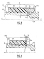
- ― la Fig. 5 est une vue en coupe axiale partielle à échelle agrandie du vérin à vis des Figs 3 et 4, au niveau de son écrou composite;
- ― la Fig. 6 est une vue en coupe axiale partielle analogue à la Fig. 5 d'une seconde forme de réalisation du vérin à vis selon l'invention;
- ― la Fig. 7 est une vue en perspective de l'écrou du vérin à vis de la Fig. 6.
- On voit à la Fig. 1 un siège 1, par exemple de véhicule automobile, monté sur un plancher fixe 2 et déplaçable longitudinalement sur celui-ci au moyen d'un ensemble 3 de glissières. L'ensemble 3 comprend un coulisseau 6 solidaire du siège 1 et qui porte une attache 4 de ceinture de sécurité (non représentée) et une glissière 5 fixée au plancher 2 par des vis 7, et sur laquelle le coulisseau 6 peut être déplacé longitudinalement en même temps que le siège 1 pour régler la position de celui-ci.
- Le coulisseau 6 est équipé d'un vérin télescopique V à sécurité de surcharge et qui permet le réglage de la position longitudinale du siège 1. Le vérin V est décrit ci-après en référence plus particulièrement aux figures 2 à 5.
- Ce vérin V comprend une vis primaire tubulaire 10, qui peut être entraînée en rotation et en translation par des moyens connus en soi et non représentés, tels que ceux décrits dans le document précité, de préférence motorisés. La vis primaire 10 est pourvue d'un filetage extérieur 10a et d'un filetage intérieur 10b dont les pas sont contraires, le filetage intérieur 10b n'étant formé que sur une partie de la longueur de la vis 10 à partir de l'une de ses extrémités.
- Le vérin V comprend également une vis secondaire fixe 11 engagée dans le filetage intérieur 10b, avec lequel elle est en prise et dont une extrémité 11a est articulée sur une bride 12 fixée au plancher 2 du véhicule. Enfin le vérin V comprend un écrou 9 engrenant avec le filetage extérieur 10a de la vis primaire 10. L'écrou 9 est logé dans une cage 13 fixée sur le coulisseau 6 par tout moyen approprié, par exemple par des points de soudure 13a.
- L'écrou 9 est composite et comprend un premier écrou 9a réalisé en une matière plastique à bon coefficient de frottement, tel que par exemple un polyacétal, et un second écrou 9b constitué en une matière mécaniquement beaucoup plus résistante que le plastique de l'écrou 9a, par exemple de l'acier.
- A titre indicatif numérique, la matière dont est constitué l'écrou 9a est choisie de manière que celui-ci puisse résister à des efforts axiaux habituels de 100 daN environ, tandis que la matière de l'écrou 9B est choisie pour que celui-ci puisse résister sans rupture à des efforts axiaux exceptionnels pouvant atteindre 2000 daN.
- Les vis 10 et 11 et l'écrou 9 ont un axe commun X parallèle au coulisseau 6.
- Les deux écrous 9a et 9b sont placés côte à côte dans la cage 13, l'écrou 9b étant placé d'un côté ou de l'autre de celui-ci.
- L'écrou 9a est réalisé avec un filetage qui engrène sans jeu sur le filetage 10a de la vis 10, tandis que le second écrou 9b est muni d'un filetage 9c présentant un jeu J (Fig. 5) avec celui de la vis primaire 10.
- Avantageusement, le jeu J est partagé entre les jeux J1 et J2 de façon à assurer les mêmes propriétés dans les deux sens de marche.
- L'effet technique du vérin à vis qui vient d'être décrit est le suivant: en fonctionnement normal c'est-dire lorsque l'élément déplaçable dont la position doit être réglée par le vérin V, par exemple un siège 1 de véhicule automobile, ne subit que des efforts axiaux d'amplitude normale, ceux-ci sont absorbés par l'écrou 9a dont le frottement sur la vis primaire 10 est très faible, ce qui assure au vérin un excellent rendement. Par contre, en cas de surcharge axiale exceptionnelle, notamment provoquée par une collision du véhicule équipé du siège 1, l'écrou plastique 9a cède et l'écrou 9b prend le relais après rattrapage du jeu J1 ou J2. Le filetage 9c de l'écrou 9b coopère alors avec le filetage 10a de telle sorte que l'écrou 9b, maintenu par la cage 13 solidaire du coulisseau 6, résiste à cette surcharge brutale et empêche l'arrachage du siège 1 des vis 10 et 11, assurant ainsi la sécurité recherchée dans un tel cas.
- La seconde forme de réalisation du vérin à vis selon l'invention, illustrée aux figures 6 et 7, diffère de la précédente essentiellement par le fait que le second écrou résistant fait ici partie intégrante de la cage contenant le premier écrou.
- En effet, dans ce mode de réalisation l'écrou 9d en matière plastique est contenu dans une cage 14 dont l'une 15 de ses ouvertures 15, 16 traversée par la vis primaire 10 est délimitée par un pourtour 9e en forme de filet. Ce filet 9e présente une extrémité saillante 17 décalée axialement d'un pas par rapport à la partie diamétralement opposée du filet, l'épaisseur du filet du pourtour 9e déterminant les jeux J1 et J2.
- En cas de surcharge exceptionnelle exercée axialement sur le vérin, cette surcharge est absorbée par le filet 9e formant écrou de sécurité et après rattrapage du jeu J1 ou J2.
- L'invention n'est pas limitée au deux formes de réalisation décrites ci-dessus et peut comporter des variantes d'exécution dans le cadre des revendications annexées. De plus le vérin à vis conforme à l'invention est susceptible de recevoir de nombreuses applications en dehors de celle décrite ci-dessus pour un siège de véhicule automobile, tout élément déplaçable susceptible de recevoir des surcharges exceptionnelles pouvant être équipé de ce vérin.
Claims (4)
Applications Claiming Priority (2)
| Application Number | Priority Date | Filing Date | Title |
|---|---|---|---|
| FR8713917 | 1987-10-08 | ||
| FR8713917A FR2621666B1 (fr) | 1987-10-08 | 1987-10-08 | Verin a vis a securite de surcharge pour element deplacable, tel qu'un siege |
Publications (2)
| Publication Number | Publication Date |
|---|---|
| EP0311478A1 EP0311478A1 (fr) | 1989-04-12 |
| EP0311478B1 true EP0311478B1 (fr) | 1991-07-17 |
Family
ID=9355634
Family Applications (1)
| Application Number | Title | Priority Date | Filing Date |
|---|---|---|---|
| EP88402412A Expired - Lifetime EP0311478B1 (fr) | 1987-10-08 | 1988-09-23 | Vérin à vis à sécurité de surcharge pour élément déplaçable, tel qu'un siège |
Country Status (9)
| Country | Link |
|---|---|
| US (1) | US4872903A (fr) |
| EP (1) | EP0311478B1 (fr) |
| JP (1) | JPH01127596A (fr) |
| BR (1) | BR8805151A (fr) |
| CA (1) | CA1289449C (fr) |
| DE (1) | DE3863738D1 (fr) |
| ES (1) | ES2025313B3 (fr) |
| FR (1) | FR2621666B1 (fr) |
| MX (1) | MX170166B (fr) |
Families Citing this family (45)
| Publication number | Priority date | Publication date | Assignee | Title |
|---|---|---|---|---|
| US5325732A (en) * | 1989-12-15 | 1994-07-05 | Vogel Ferdinand L | Motion-transmitting combination comprising a castable, self-lubricating composite and methods of manufacture thereof |
| DE4019482A1 (de) * | 1990-06-19 | 1992-01-09 | Diehl Gmbh & Co | Ruderstelleinrichtung |
| US5117700A (en) * | 1991-02-25 | 1992-06-02 | Ross-Hime Designs, Incorporated | Miniature linear actuator |
| JPH0742859Y2 (ja) * | 1991-08-30 | 1995-10-04 | 池田物産株式会社 | パワーシートスライド装置 |
| US5425282A (en) * | 1991-10-21 | 1995-06-20 | Luigs; Willi | Manipulator |
| EP0549082B1 (fr) * | 1991-12-13 | 1996-12-18 | Brose Fahrzeugteile GmbH & Co. KG | Glissière |
| ES2098571T3 (es) * | 1992-02-18 | 1997-05-01 | Krzysztof Dudzik | Robot de brazo. |
| US5261644A (en) * | 1992-10-08 | 1993-11-16 | Seeburn Metal Products Limited | Plastic jack |
| US5553825A (en) * | 1992-11-30 | 1996-09-10 | Rasmussen; C. Martin | Mechanical camper jack |
| US5620166A (en) * | 1994-08-02 | 1997-04-15 | Lord; Bruce A. | Stem and nut with bearing for use in a motor operated valve |
| DK1134454T3 (da) * | 1994-12-23 | 2004-08-02 | Linak As | En mötrikenhed til en lineær aktuator |
| US5860319A (en) * | 1996-12-19 | 1999-01-19 | Lear Corporation | Reduced noise drive block for vehicle seat adjuster |
| US5797293A (en) * | 1996-12-19 | 1998-08-25 | Lear Corporation | Plastic drive block for vehicle seat adjuster |
| US5797574A (en) * | 1996-12-23 | 1998-08-25 | Lear Corporation | Drive nut apparatus for vehicle seat adjuster |
| US5884970A (en) * | 1997-06-09 | 1999-03-23 | Counterbalance Corporation | Recliner apparatus |
| US5984353A (en) * | 1997-07-02 | 1999-11-16 | Rasmussen; C. Martin | Quick-release arrangement for a camper jack system |
| US5971482A (en) * | 1997-10-02 | 1999-10-26 | Invacare Corporation | Constant center of gravity tiltable chair of a wheelchair |
| US6053064A (en) * | 1998-05-01 | 2000-04-25 | L & P Property Management Company | Lumbar support screw actuator |
| US6338523B1 (en) | 1999-11-23 | 2002-01-15 | Happijac Company | Sliding mechanisms and systems |
| US6981728B2 (en) | 1999-11-23 | 2006-01-03 | Happijac Company | Sliding mechanisms and systems |
| FR2837148B1 (fr) * | 2002-03-18 | 2004-07-02 | Faurecia Sieges Automobile | Mecanisme de reglage pour glissiere de siege de vehicule automobile ainsi que glissiere et siege equipes d'un tel mecanisme |
| DE10235086B4 (de) * | 2002-07-31 | 2009-10-29 | Johnson Controls Gmbh | Sicherheitseinrichtung für Fahrzeugsitze |
| DE20214565U1 (de) * | 2002-09-20 | 2004-03-04 | Dewert Antriebs- Und Systemtechnik Gmbh & Co Kg | Elektromotorischer Möbelantrieb |
| US6976721B2 (en) | 2003-03-05 | 2005-12-20 | Happijac Company | Slide-out mechanisms and systems |
| EP1800025B1 (fr) * | 2004-09-29 | 2013-01-16 | Linak A/S | Actionneur lineaire |
| FR2876756B1 (fr) * | 2004-10-19 | 2007-01-05 | Patrick Lambert | Verin a vis |
| EP1674764B1 (fr) * | 2004-12-22 | 2010-06-30 | Ab Skf | Ecrou d'engrenage pour dispositif actionneur linéaire |
| FR2901780B1 (fr) * | 2006-05-30 | 2009-03-06 | Sefac Sa | Dispositif de levage a ecrou parachute |
| US7802953B2 (en) * | 2007-03-16 | 2010-09-28 | Robert Stephen | Inset panel fastener |
| US20090155017A1 (en) * | 2007-11-16 | 2009-06-18 | Tiodize Co., Inc. | Secure composite fastener |
| US8393601B2 (en) | 2008-10-04 | 2013-03-12 | Applied Concepts Aircraft Solutions, Inc. | Vibration isolation fastener insert |
| DE202009001847U1 (de) | 2009-02-11 | 2010-07-01 | Brose Fahrzeugteile Gmbh & Co. Kommanditgesellschaft, Coburg | Spindelantrieb für eine Sitzlängsverstellung eines Kraftfahrzeugsitzes |
| CN102705463A (zh) * | 2012-06-13 | 2012-10-03 | 天润曲轴股份有限公司 | 一种差动螺旋微调装置 |
| US9140279B2 (en) | 2012-09-25 | 2015-09-22 | The Young Engineers, Inc. | Magnetic mount |
| EP2716935A1 (fr) * | 2012-10-03 | 2014-04-09 | Linak A/S | Actionneur linéaire |
| JP6189034B2 (ja) * | 2012-12-26 | 2017-08-30 | シロキ工業株式会社 | シートスライド装置 |
| JP6364915B2 (ja) * | 2014-04-18 | 2018-08-01 | アイシン精機株式会社 | 車両用シートスライド装置 |
| JP6548892B2 (ja) * | 2014-11-17 | 2019-07-24 | シロキ工業株式会社 | ナットの製造方法 |
| US10493867B2 (en) | 2015-03-24 | 2019-12-03 | Adient Luxembourg Holding S.à.r.l. | Adjusting device for a vehicle seat and vehicle seat |
| DE102015212448B4 (de) * | 2015-07-02 | 2020-07-02 | Zf Friedrichshafen Ag | Spindelantrieb und Aktuator mit einem Spindelantrieb |
| DE102018116897A1 (de) | 2018-07-12 | 2020-01-16 | Schaeffler Technologies AG & Co. KG | Kugelgewindetrieb |
| US11168770B2 (en) * | 2019-05-23 | 2021-11-09 | Brose Fahrzeugteile Gmbh & Co. Kommanditgesellschaft, Bamberg | Vehicle drive mechanism |
| KR102291150B1 (ko) * | 2020-02-18 | 2021-08-18 | 현대트랜시스 주식회사 | 시트용 레일의 리드 너트 보강구조 |
| KR102793679B1 (ko) * | 2022-05-09 | 2025-04-09 | 현대트랜시스 주식회사 | 차량용 시트 이동 장치 |
| WO2026068995A1 (fr) * | 2024-09-30 | 2026-04-02 | Safran Seats Usa Llc | Dossier télescopique pour sièges |
Family Cites Families (8)
| Publication number | Priority date | Publication date | Assignee | Title |
|---|---|---|---|---|
| US2215107A (en) * | 1937-12-11 | 1940-09-17 | Mulka Friedrich | Screw feed mechanism |
| DE853082C (de) * | 1942-03-03 | 1952-10-20 | Bisterfeld & Stolting | Spindelmutter, bestehend aus einem metallischen Grundkoerper mit einem eingesetzten Kunststoffgewinde |
| GB652199A (en) * | 1948-12-23 | 1951-04-18 | Mb Wild & Co Ltd | Improvements relating to screw-jack and like mechanisms |
| GB1068231A (en) * | 1964-01-23 | 1967-05-10 | British Aircraft Corp Ltd | Improvements in screw-and-nut mechanisms incorporating recirculating ball screws |
| CH437700A (fr) * | 1965-07-22 | 1967-06-15 | Villars Julio | Elévateur pour automobiles |
| US3799292A (en) * | 1972-01-05 | 1974-03-26 | Astro Dynamics Inc | Screw-nut and nut follower-controlled lift apparatus and components |
| FR2447494A1 (fr) * | 1979-01-24 | 1980-08-22 | Mecanismes Comp Ind De | Dispositif de reglage de la position d'un element deplacable dans un vehicule, tel que le siege de celui-ci |
| DE2906172C2 (de) * | 1979-02-17 | 1984-04-12 | Gebr. Hofmann Gmbh & Co Kg Maschinenfabrik, 6100 Darmstadt | Sicherheitseinrichtung für eine spindelbetriebene Hebeeinrichtung, insbesondere Zwei-Säulen-Kraftfahrzeug-Hebebühne |
-
1987
- 1987-10-08 FR FR8713917A patent/FR2621666B1/fr not_active Expired - Fee Related
-
1988
- 1988-08-08 MX MX012587A patent/MX170166B/es unknown
- 1988-09-23 EP EP88402412A patent/EP0311478B1/fr not_active Expired - Lifetime
- 1988-09-23 ES ES88402412T patent/ES2025313B3/es not_active Expired - Lifetime
- 1988-09-23 DE DE8888402412T patent/DE3863738D1/de not_active Expired - Lifetime
- 1988-10-03 US US07/252,216 patent/US4872903A/en not_active Expired - Fee Related
- 1988-10-03 CA CA000579102A patent/CA1289449C/fr not_active Expired - Fee Related
- 1988-10-06 BR BR8805151A patent/BR8805151A/pt unknown
- 1988-10-07 JP JP63252174A patent/JPH01127596A/ja active Pending
Also Published As
| Publication number | Publication date |
|---|---|
| DE3863738D1 (de) | 1991-08-22 |
| JPH01127596A (ja) | 1989-05-19 |
| CA1289449C (fr) | 1991-09-24 |
| US4872903A (en) | 1989-10-10 |
| BR8805151A (pt) | 1989-05-16 |
| FR2621666A1 (fr) | 1989-04-14 |
| FR2621666B1 (fr) | 1990-02-23 |
| ES2025313B3 (es) | 1992-03-16 |
| EP0311478A1 (fr) | 1989-04-12 |
| MX170166B (es) | 1993-08-10 |
Similar Documents
| Publication | Publication Date | Title |
|---|---|---|
| EP0311478B1 (fr) | Vérin à vis à sécurité de surcharge pour élément déplaçable, tel qu'un siège | |
| EP0755844B1 (fr) | Dispositif d'absorption d'énergie et de guidage pour colonne de direction de véhicule automobile | |
| EP0586409B1 (fr) | Ensemble tubulaire telescopique a cannelures | |
| EP1400405B1 (fr) | Projecteur comportant des moyens d'absorption d'énergie | |
| BE1011465A6 (fr) | Helice de propulsion. | |
| FR2626227A1 (fr) | Limiteur d'effort pour systemes de ceinture de securite | |
| WO2009080973A2 (fr) | Dispositif et ensemble d'absorption d'énergie renforcés | |
| FR2536125A1 (fr) | Dispositif pour rendre uniforme la course d'un embrayage hydraulique, notamment d'un vehicule automobile | |
| EP0655383B1 (fr) | Dispositif d'absorption d'énergie pour colonne de direction de véhicule automobile | |
| EP2172369B1 (fr) | Dispositif de protection d'une piece de carrosserie de vehicule automobile | |
| EP1747124B1 (fr) | Suort de butee d'un caot avant d'un vehicule automobile | |
| EP0216678A1 (fr) | Sous-ensemble télescopique pour colonne de direction | |
| EP0685374A1 (fr) | Moto-réducteur, notamment pour un dispositif d'essuie-glace de véhicule | |
| WO2008149043A2 (fr) | Ensemble d'absorption d'énergie comprenant un dispositif anti-retour | |
| EP0424204B1 (fr) | Mécanisme de liaison entre une poignée d'ouverture et une tringle de commande d'une serrure de porte de véhicule | |
| FR2885574A1 (fr) | Pedalier de vehicule automobile apte, en cas de choc frontal sur le vehicule, a se retracter | |
| EP0336837A1 (fr) | Dispositif de blocage automatique de tubes téléscopiques en position déployée | |
| FR2671316A1 (fr) | Ensemble pare-chocs pour vehicules. | |
| EP2038163A2 (fr) | Dispositif de protection contre un choc frontal d'une cassette de refroidissement d'un vehicule | |
| EP1211380A1 (fr) | Treuil à vis sans fin pour store ou volet roulant | |
| FR2887210A1 (fr) | Dispositif absorbeur d'energie pour poutre pare-chocs de vehicule automobile | |
| FR2891236A1 (fr) | Capot de vehicule automobile destine a fermer un compartiment moteur contenant des pieces rigides | |
| FR2776240A1 (fr) | Dispositif de remorquage d'un vehicule automobile comprenant un anneau escamotable en cas de choc | |
| EP0667277B1 (fr) | Système anti-remontée de l'axe volant d'une colonne de direction | |
| FR2496036A3 (fr) | Armature metallique pour un volant de direction |
Legal Events
| Date | Code | Title | Description |
|---|---|---|---|
| PUAI | Public reference made under article 153(3) epc to a published international application that has entered the european phase |
Free format text: ORIGINAL CODE: 0009012 |
|
| AK | Designated contracting states |
Kind code of ref document: A1 Designated state(s): DE ES GB IT SE |
|
| 17P | Request for examination filed |
Effective date: 19890721 |
|
| RAP1 | Party data changed (applicant data changed or rights of an application transferred) |
Owner name: ROCKWELL AUTOMOTIVE BODY SYSTEMS-FRANCE EN ABREGE: |
|
| 17Q | First examination report despatched |
Effective date: 19901102 |
|
| ITF | It: translation for a ep patent filed | ||
| GRAA | (expected) grant |
Free format text: ORIGINAL CODE: 0009210 |
|
| AK | Designated contracting states |
Kind code of ref document: B1 Designated state(s): DE ES GB IT SE |
|
| GBT | Gb: translation of ep patent filed (gb section 77(6)(a)/1977) | ||
| REF | Corresponds to: |
Ref document number: 3863738 Country of ref document: DE Date of ref document: 19910822 |
|
| REG | Reference to a national code |
Ref country code: ES Ref legal event code: FG2A Ref document number: 2025313 Country of ref document: ES Kind code of ref document: B3 |
|
| PLBE | No opposition filed within time limit |
Free format text: ORIGINAL CODE: 0009261 |
|
| STAA | Information on the status of an ep patent application or granted ep patent |
Free format text: STATUS: NO OPPOSITION FILED WITHIN TIME LIMIT |
|
| 26N | No opposition filed | ||
| PGFP | Annual fee paid to national office [announced via postgrant information from national office to epo] |
Ref country code: SE Payment date: 19920929 Year of fee payment: 5 |
|
| PGFP | Annual fee paid to national office [announced via postgrant information from national office to epo] |
Ref country code: ES Payment date: 19920930 Year of fee payment: 5 |
|
| PGFP | Annual fee paid to national office [announced via postgrant information from national office to epo] |
Ref country code: GB Payment date: 19930923 Year of fee payment: 6 |
|
| PG25 | Lapsed in a contracting state [announced via postgrant information from national office to epo] |
Ref country code: SE Effective date: 19930924 Ref country code: ES Free format text: LAPSE BECAUSE OF EXPIRATION OF PROTECTION Effective date: 19930924 |
|
| PGFP | Annual fee paid to national office [announced via postgrant information from national office to epo] |
Ref country code: DE Payment date: 19940727 Year of fee payment: 7 |
|
| PG25 | Lapsed in a contracting state [announced via postgrant information from national office to epo] |
Ref country code: GB Effective date: 19940923 |
|
| EUG | Se: european patent has lapsed |
Ref document number: 88402412.6 Effective date: 19940410 |
|
| GBPC | Gb: european patent ceased through non-payment of renewal fee |
Effective date: 19940923 |
|
| PG25 | Lapsed in a contracting state [announced via postgrant information from national office to epo] |
Ref country code: DE Effective date: 19960601 |
|
| REG | Reference to a national code |
Ref country code: ES Ref legal event code: FD2A Effective date: 19991007 |
|
| PG25 | Lapsed in a contracting state [announced via postgrant information from national office to epo] |
Ref country code: IT Free format text: LAPSE BECAUSE OF NON-PAYMENT OF DUE FEES Effective date: 20050923 |