EP0311800A2 - Verfahren zum Steuern der Wickelspannung einer Fadenschar beim Bilden eines Wickels - Google Patents
Verfahren zum Steuern der Wickelspannung einer Fadenschar beim Bilden eines Wickels Download PDFInfo
- Publication number
- EP0311800A2 EP0311800A2 EP88114992A EP88114992A EP0311800A2 EP 0311800 A2 EP0311800 A2 EP 0311800A2 EP 88114992 A EP88114992 A EP 88114992A EP 88114992 A EP88114992 A EP 88114992A EP 0311800 A2 EP0311800 A2 EP 0311800A2
- Authority
- EP
- European Patent Office
- Prior art keywords
- winder
- winding
- speed
- dancer roller
- thread sheet
- Prior art date
- Legal status (The legal status is an assumption and is not a legal conclusion. Google has not performed a legal analysis and makes no representation as to the accuracy of the status listed.)
- Granted
Links
- 238000000034 method Methods 0.000 title claims abstract description 8
- 230000001105 regulatory effect Effects 0.000 title claims description 4
- 230000015572 biosynthetic process Effects 0.000 title 1
- 238000004804 winding Methods 0.000 claims abstract description 34
- 230000001276 controlling effect Effects 0.000 claims description 3
- 238000005259 measurement Methods 0.000 claims description 3
- 230000000284 resting effect Effects 0.000 claims description 3
- 238000010276 construction Methods 0.000 claims description 2
- 230000003068 static effect Effects 0.000 abstract description 7
- 239000000463 material Substances 0.000 description 3
- 238000002604 ultrasonography Methods 0.000 description 3
- 230000002093 peripheral effect Effects 0.000 description 2
- 239000004753 textile Substances 0.000 description 2
- 230000006978 adaptation Effects 0.000 description 1
- 238000001514 detection method Methods 0.000 description 1
- 238000010586 diagram Methods 0.000 description 1
Images
Classifications
-
- D—TEXTILES; PAPER
- D02—YARNS; MECHANICAL FINISHING OF YARNS OR ROPES; WARPING OR BEAMING
- D02H—WARPING, BEAMING OR LEASING
- D02H13/00—Details of machines of the preceding groups
- D02H13/12—Variable-speed driving mechanisms
- D02H13/14—Variable-speed driving mechanisms controlled automatically by tension in the warp
-
- B—PERFORMING OPERATIONS; TRANSPORTING
- B65—CONVEYING; PACKING; STORING; HANDLING THIN OR FILAMENTARY MATERIAL
- B65H—HANDLING THIN OR FILAMENTARY MATERIAL, e.g. SHEETS, WEBS, CABLES
- B65H23/00—Registering, tensioning, smoothing or guiding webs
- B65H23/04—Registering, tensioning, smoothing or guiding webs longitudinally
- B65H23/18—Registering, tensioning, smoothing or guiding webs longitudinally by controlling or regulating the web-advancing mechanism, e.g. mechanism acting on the running web
- B65H23/195—Registering, tensioning, smoothing or guiding webs longitudinally by controlling or regulating the web-advancing mechanism, e.g. mechanism acting on the running web in winding mechanisms or in connection with winding operations
- B65H23/1955—Registering, tensioning, smoothing or guiding webs longitudinally by controlling or regulating the web-advancing mechanism, e.g. mechanism acting on the running web in winding mechanisms or in connection with winding operations and controlling web tension
-
- B—PERFORMING OPERATIONS; TRANSPORTING
- B65—CONVEYING; PACKING; STORING; HANDLING THIN OR FILAMENTARY MATERIAL
- B65H—HANDLING THIN OR FILAMENTARY MATERIAL, e.g. SHEETS, WEBS, CABLES
- B65H23/00—Registering, tensioning, smoothing or guiding webs
- B65H23/04—Registering, tensioning, smoothing or guiding webs longitudinally
- B65H23/18—Registering, tensioning, smoothing or guiding webs longitudinally by controlling or regulating the web-advancing mechanism, e.g. mechanism acting on the running web
- B65H23/195—Registering, tensioning, smoothing or guiding webs longitudinally by controlling or regulating the web-advancing mechanism, e.g. mechanism acting on the running web in winding mechanisms or in connection with winding operations
- B65H23/198—Registering, tensioning, smoothing or guiding webs longitudinally by controlling or regulating the web-advancing mechanism, e.g. mechanism acting on the running web in winding mechanisms or in connection with winding operations motor-controlled (Controlling electrical drive motors therefor)
-
- B—PERFORMING OPERATIONS; TRANSPORTING
- B65—CONVEYING; PACKING; STORING; HANDLING THIN OR FILAMENTARY MATERIAL
- B65H—HANDLING THIN OR FILAMENTARY MATERIAL, e.g. SHEETS, WEBS, CABLES
- B65H2701/00—Handled material; Storage means
- B65H2701/30—Handled filamentary material
- B65H2701/38—Thread sheet, e.g. sheet of parallel yarns or wires
Definitions
- the invention relates to a method for controlling the winding tension of a family of threads when forming a winding, in which the family of threads is fed to a driven winder via a driven pair of transport rollers and a dancer roller, in which the family of threads is further loaded, preferably pneumatically, on the dancer roller on the one hand and by a Circumferential speed difference between the pair of transport rollers and the winder is tensioned, on the other hand, and the winder speed is regulated relative to the transport roller speed with the aid of a programmable logic controller (PLC control).
- PLC control programmable logic controller
- the textile thread sheet to be wound is fed to the actual winder with the winding tree via a pair of transport rollers and a dancer roller.
- the winding tension of the thread sheet is generated by loading the dancer roller, in particular by pneumatic action on the dancer roller.
- the corresponding counter tension is obtained by setting a difference in the peripheral speed of the pair of transport rollers and the winding beam.
- the dancer roller can basically perform movements following a changing tension of the thread coulter when the winder is operating, but in order to maintain a winding tension that is as constant as possible, it is necessary to specify a static resting point or working point of the dancer roller by the mechanical construction of the system and to keep it as precisely as possible during operation , the dancer roller is therefore only allowed to be very minimal Remove amounts on the order of 1 cm or less from the area of the specified static resting point. It is therefore not suitable for a basic control or rough correction of the winder speed in relation to the delivery speed of the thread group, that is to say the transport rollers which are in principle driven independently of the winder.
- the invention has for its object to adjust the speed of the winding drive to the growing diameter of the winding so that the dancer roller is deflected as little as possible from the predetermined static point of rest.
- the control system should be designed in such a way that manual regulation is not necessary; in particular, it should also be possible to start a winding process independently of the winding diameter without manual presetting.
- the solution according to the invention for the above-mentioned method for controlling the winding tension consists in that the actual diameter of the winding is determined by ultrasonic distance measurement, converted into an analog output signal and fed to an analog input of a programmable logic controller as a controlled variable or rough correction value for the winding speed and that the signal of an analog dancer roll control with PID behavior is additionally supplied to the speed setpoint signal of the winding drive.
- the actual diameter of the roll By scanning the actual diameter of the roll according to the invention with the aid of an ultrasonic range finder with an analog output signal and by forwarding This signal to a programmable logic controller enables a rough adjustment of the speed of the winding drive to the current winding diameter. If necessary, the actual diameter is determined from the ultrasound signal, checked for plausibility (e.g. a question is asked as to whether the winder is empty or there is a faulty measurement) and processed to an average. A pre-control value for the winder speed is calculated from the current diameter found in this way and the target value for the material speed.
- plausibility e.g. a question is asked as to whether the winder is empty or there is a faulty measurement
- the aforementioned rough adjustment of winder speed and winder diameter in relation to the delivery speed of the thread sheet is supplemented according to the invention by a fine adjustment.
- the dancer roller which can be deflected from its static point of rest to a small extent during operation, serves this purpose.
- the residual errors remaining for fine tuning as well as dynamic deviations and out-of-roundness of the growing reel, but also changes in the elasticity of the wound material, are eliminated by an analogous position control of the dancer roll with PID behavior by adding the signal of this control additively to the speed pre-control determined in the above-mentioned coarse adjustment.
- Setpoint signal of the winding drive is supplied.
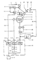
- the textile thread sheet 1 to be wound is passed in the direction of the arrow 2 via a pair of transport rollers 3 and a dancer roller 4 to a winding 5 which is being formed in a winder which is denoted overall by 6.
- the winding tension FW of the thread sheet 1 is generated by acting on the dancer roller 4 with the aid of a pneumatic cylinder 7.
- the associated counter-voltage is obtained by setting a difference between the delivery speed of the pair of transport rollers 3 and the peripheral speed of the winding 5 that is being formed.
- the pair of transport rollers has a drive 8, in particular a controlled direct current motor delivering an output speed n1.
- the winder 6 has a drive 8 which is independent of the drive 8 of the pair of transport rollers, in particular also a controlled DC motor which supplies the output speed n2.
- the actual diameter of the winding 5 growing in the winder 6 is scanned with the aid of an ultrasound range finder or ultrasound sensor 10.
- This ultrasonic sensor 10 is intended to conduct an analog output signal on line 11 to a programmable logic controller (PLC), designated as a whole at 12, at its input 13. From the distance signal from the sensor 10, the actual diameter of the winding 5 is digitized in the PLC controller 12 in an analog / digital converter 14 and as the mean value of the actual diameter for the rough adjustment of a pilot control setpoint 16 Ratio of the speed of the transport roller pair 3 and the winder 6 used.
- PLC programmable logic controller
- a master setpoint is specified at an input 17 of the PLC controller 12 as the speed of the drive 8 of the pair of transport rollers 3.
- the digitized master setpoint is fed via a line 20 to the control part 21 of the drive 8 via a digital / analog converter 18 and an output 19 of the PLC control 12.
- the setpoint is fed from the input 17 via the n1 / n2 computer in the pilot control setpoint part 16 to an analog-digital converter 22 and via an output 23 of the PLC controller 12 and a line 24 to the control part 25 of the drive 9 of the winder 6.
- the speed of the winder drive 9 is adapted to the growing diameter of the winder 5 in such a way that the dancer roller 4 is deflected as little as possible from its predetermined static rest point. Since the current winding diameter constantly enters the speed ratio n1 / n2 via the PLC control 12, the winding process can be started with any winding diameter without mechanical presetting.
- the dancer roller 4 is usually mounted on the free end of an arm 26, while the arm 26 can be moved back and forth in the direction of the arrow 27 about a pivot bearing 28.
- the deflection position by the angle w from the static rest point shown is detected by a potentiometer 29.
- the potentiometer signal is fed to a PID controller 31 via a power 30.
- the output signal of the PID controller 31 is superimposed on the analog signal of the pilot control setpoint 16 coming from the output 23 of the PLC control 12 in such a way that possible deflections of the dancer roller 4 are regulated to a minimum by an angle w in the direction of arrow 27 from the predetermined rest position.
Landscapes
- Engineering & Computer Science (AREA)
- Textile Engineering (AREA)
- Controlling Rewinding, Feeding, Winding, Or Abnormalities Of Webs (AREA)
- Unwinding Of Filamentary Materials (AREA)
- Tension Adjustment In Filamentary Materials (AREA)
- Warping, Beaming, Or Leasing (AREA)
Abstract
Description
- Die Erfindung betrifft ein Verfahren zum Steuern der Wickelspannung einer Fadenschar beim Bilden eines Wickels, bei dem die Fadenschar über ein angetriebenes Transportwalzenpaar und eine Tänzerwalze einem angetriebenen Wickler zugeführt wird, bei dem ferner die Fadenschar durch, vorzugsweise pneumatisches, Belasten der Tänzerwalze einerseits sowie durch eine Umfangsgeschwindigkeitsdifferenz von Transportwalzenpaar und Wickler andererseits gespannt wird und bei dem die Wicklerdrehzahl relativ zur Transportwalzendrehzahl mit Hilfe einer speicherprogrammierbaren Steuerung (SPS-Steuerung) geregelt wird.
- Beim Bilden von Kettbäumen, Schärbäumen oder dergleichen wird die aufzuwickelnde textile Fadenschar über ein Transportwalzenpaar und eine Tänzerwalze dem eigentlichen Wickler mit dem Wickelbaum zugeführt. Die Aufwickelspannung der Fadenschar wird durch Belastung der Tänzerwalze, insbesondere durch pneumatisches Beaufschlagen der Tänzerwalze, erzeugt. Die entsprechende Gegenspannung wird durch Einstellen einer Differenz der Umfangsgeschwindigkeit von Transportwalzenpaar und Wickelbaum erhalten.
- Die Tänzerwalze kann zwar bei Betrieb des Wicklers grundsätzlich einer wechselnden Spannung der Fadenschar folgend Bewegungen ausführen, zum Einhalten einer möglichst konstanten Wickelspannung ist es aber erforderlich, einen statischen Ruhepunkt bzw. Arbeitspunkt der Tänzerwalze durch die mechanische Konstruktion der Anlage vorzugeben und bei Betrieb möglichst genau einzuhalten, die Tänzerwalze darf sich also nur um ganz minimale Beträge in der Größenordnung von höchstens 1 cm, aus dem Bereich des vorgegebenen statischen Ruhepunkts entfernen. Sie ist daher für eine grundsätzliche Regelung bzw. Grob-Korrektur der Wicklerdrehzahl in Bezug auf die Liefergeschwindigkeit der Fadenschar, das heißt der im Prinzip unabhängig vom Wickler angetriebenen Transportwalzen, nicht geeignet.
- Der Erfindung liegt die Aufgabe zugrunde, die Drehzahl des Wickelantriebs auf den wachsenden Durchmesser des Wickels so abzustimmen, daß die Tänzerwalze möglichst wenig aus dem vorgegebenen statischen Ruhepunkt ausgelenkt wird. Die Steuerung soll so ausgebildet werden, daß eine manuelle Regulierung nicht erforderlich ist, insbesondere soll auch der Start eines Wickelvorgangs unabhängig vom Wickeldurchmesser ohne manuelle Voreinstellung möglich sein.
- Die erfindungsgemäße Lösung besteht für das eingangs genannte Verfahren zum Steuern der Wickelspannung darin, daß der Ist-Durchmesser des Wickels durch Ultraschall-Entfernungsmessung ermittelt, in ein analoges Ausgangssignal umgewandelt sowie als Regelgröße bzw. Grob-Korrekturwert der Wicklerdrehzahl einem Analogeingang einer speicherprogrammierbaren Steuerung zugeführt wird und daß das Signal einer analogen Tänzerwalzenregelung mit PID-Verhalten additiv dem Drehzahl-Sollwert-Signal des Wickelantriebs zugeführt wird.
- Durch das erfindungsgemäße Abtasten des Ist-Durchmessers des Wickels mit Hilfe eines Ultraschall-Entfernungsmessers mit analogem Ausgangssignal und durch Weiterleitung dieses Signals an eine speicherprogrammierbare Steuerung wird eine Grobabstimmung der Drehzahl des Wickelantriebs auf den aktuellen Wickeldurchmesser ermöglicht. Gegebenenfalls wird der Ist-Durchmesser aus dem Ultraschall-Signal ermittelt, auf Plausibilität überprüft (z. B. wird gefragt, ob der Wickler leer ist oder eine Fehlmessung vorliegt) und zu einem Mittelwert verarbeitet. Aus dem so gefundenen aktuellen Durchmesser und dem Sollwert für die Materialgeschwindigkeit wird ein Vorsteuerwert für die Wicklerdrehzahl errechnet.
- Die vorgenannte Grobabstimmung von Wicklerdrehzahl und Wicklerdurchmesser in Bezug auf die Liefergeschwindigkeit der Fadenschar wird erfindungsgemäß durch eine Feinabstimmung ergänzt. Hierzu dient die wenig, aber doch in geringem Maße bei Betrieb aus ihrem statischen Ruhepunkt auszulenkende Tänzerwalze. Der für eine Feinabstimmung verbleibende Restfehler sowie dynamische Abweichungen und Unrundheiten des wachsenden Wickels, aber auch Elastizitätsveränderungen des gewickelten Materials werden durch eine analoge Lagenregelung der Tänzerwalze mit PID-Verhalten beseitigt, indem das Signal dieser Regelung additiv dem bei der vorgenannten Grobabstimmung ermittelten Drehzahl-Vorsteuer-Sollwert-Signal des Wickelantriebs zugeführt wird.
- Anhand der schematischen Darstellung eines Wirkschaltbildes als Ausführungsbeispiel einer Wickelsteuerung mit Ultraschall-Durchmesser-Erfassung werden Einzelheiten der Erfindung erläutert.
- Die aufzuwickelnde textile Fadenschar 1 wird in Pfeilrichtung 2 über ein Transportwalzenpaar 3 und eine Tänzerwalze 4 auf einen sich bildenden Wickel 5 eines insgesamt mit 6 bezeichneten Wicklers geleitet. Die Aufwickel-Spannung FW der Fadenschar 1 wird durch Beaufschlagung der Tänzerwalze 4 mit Hilfe eines Pneumatikzylinders 7 erzeugt. Die zugehörige Gegenspannung wird durch Einstellung einer Differenz der Liefergeschwindigkeit des Transportwalzenpaars 3 und der Umfangsgeschwindigkeit des sich bildenden Wickels 5 erhalten Das Transportwalzenpaar besitzt einen Antrieb 8, insbesondere einen eine Ausgangsdrehzahl n1 liefernden gesteuerten Gleichstrommotor. Der Wickler 6 besitzt einen vom Antrieb 8 des Transportwalzenpaars unabhängigen Antrieb 8, insbesondere ebenfalls einen gesteuerten Gleichstrommotor, der die Ausgangsdrehzahl n2 liefert. Der Ist-Durchmesser des im Wickler 6 wachsenden Wickels 5 wird mit Hilfe eines Ultraschall-Entfernungsmessers bzw. Ultraschall-Sensors 10 abgetastet. Dieser Ultraschall-Sensor 10 soll ein analoges Ausgangssignal auf der Leitung 11 zu einer insgesamt mit 12 bezeichneten speicherprogrammierbaren Steuerung (SPS) an deren Eingang 13 leiten. Aus dem Entfernungssignal des Sensors 10 wird in der SPS-Steuerung 12 der Ist-Durchmesser des Wickels 5 in einem Analog/Digital-Wandler 14 digitalisiert und als Mittelwert des Ist-Durchmessers zur Grobabstimmung eines Vorsteuersollwertes 16 des Verhältnisses der Drehzahl des Transportwalzenpaars 3 und des Wicklers 6 verwendet.
- Als Drehzahl des Antriebs 8 des Transportwalzenpaars 3 wird ein Leitsollwert an einer Eingabe 17 der SPS-Steuerung 12 vorgegeben. Der digitalisierte Leitsollwert wird über einen Digital/Analog-Wandler 18 und einen Ausgang 19 der SPS-Steuerung 12 über eine Leitung 20 dem Steuerteil 21 des Antriebs 8 zugeführt. Zugleich wird der Sollwert von der Eingabe 17 über den n1/n2-Rechner im Vorsteuersollwertteil 16 einem Analog-Digital-Wandler 22 und über einen Ausgang 23 der SPS-Steuerung 12 sowie eine Leitung 24 dem Steuerteil 25 des Antriebs 9 des Wicklers 6 zugeführt.
- Da der Vorsteuersollwert 16 ständig durch die von dem Ultraschall-Sensor 10 kommenden Signale entsprechend dem aktuellen Wickeldurchmesser korrigiert werden, wird schon auf diese einfache Weise eine recht gute Anpassung der Wicklerdrehzahl n2 an die Transportwalzendrehzahl n1 dem jeweilig gewickelten Material entsprechend erreicht.
- Bei der vorgenannten Grob-Abstimmung wird die Drehzahl des Wicklerantriebs 9 so dem wachsenden Durchmesser des Wickels 5 angepaßt, daß die Tänzerwalze 4 möglichst wenig aus ihrem vorgegebenen statischen Ruhepunkt ausgelenkt wird. Da der aktuelle Wickeldurchmesser ständig über die SPS-Steuerung 12 in das Drehzahlverhältnis n1/n2 eingeht, kann der Wickelvorgang bei jedem Wickeldurchmesser ohne mechanische Voreinstellung gestartet werden.
- Die Tänzerwalze 4 wird üblich am freien Ende eines Arms 26 gelagert, während der Arm 26 in Pfeilrichtung 27 um ein Schwenklager 28 hin und her zu bewegen ist. Die Auslenkposition um den Winkel w aus dem dargestellten statischen Ruhepunkt wird über ein Potentiometer 29 erfaßt. Das Potentiometersignal wird über eine Leistung 30 einem PID-Regler 31 zugeführt. Das Ausgangssignal des PID-Reglers 31 wird dem vom Ausgang 23 der SPS-Steuerung 12 kommenden Analogsignal des Vorsteuer-Sollwertes 16 so überlagert, daß eventuelle Auslenkungen der Tänzerwalze 4 um einen Winkel w in Pfeilrichtung 27 aus der vorgegebenen Ruheposition auf ein Minimum geregelt werden. Auf diese Weise können nach der Grob-Abstimmung durch den Ultraschall-Sensor 10 noch verbleibende Restfehler sowie dynamische Abweichungen, die von Unrundheiten des Wickels 5 oder von Elastizitätsschwankungen der Fadenschar 1 herrühren können, wird durch die analoge PID-Tänzerlagenregelung beseitigt, wenn das Signal des PID-Reglers 31 additiv dem Drehzahl-Sollwert--Signal des Vorsteuer-Sollwert-Bildners 16 zugeführt wird.
-
- 1 = Fadenschar
- 2 = Pfeil
- 3 = Transportwalzenpaar
- 4 = Tänzerwalze
- 5 = Wickel
- 6 = Wickler
- 7 = Pneumatikzylinder
- 8 = Antrieb (3)
- 9 = Antrieb (6)
- 10 = Ultraschall-Sensor
- 11 = Leitung
- 12 = SPS-Steuerung
- 13 = Analogeingang (12)
- 14 = Analog/Digital-Wandler
- 15 = Mittlerer Ist-Durchmesser
- 16 = Vorsteuer-Sollwert n1/n2
- 17 = Eingabe (12)
- 18 = Digital/Analog-Wandler
- 19 = Analog-Ausgang (12)
- 20 = Leitung
- 21 = Steuerteil (8)
- 22 = Analog/Digital-Ausgang (12)
- 23 = Analog-Ausgang (12)
- 24 = Leitung
- 25 = Steuerteil (9)
- 26 = Arm (4)
- 27 = Pfeil
- 28 = Schwenklage
- 29 = Potentiometer
- 30 = Leitung
- 31 = PID-Regler
Claims (2)
dadurch gekennzeichnet,
daß der Ist-Durchmesser des im Wickler (6) gebildeten Wickels (5) durch Ultraschall-Entfernungsmessung (10) analog ermittelt sowie als Regelgröße bzw. Grob-Korrekturwert des Drehzahl-Sollwert-Signals des Wicklerantriebs (6) einem Analogeingang (13) der speicherprogrammierbaren Steuerung (12) zugeführt wird und daß ein an einer analogen Tänzerwalzenregelung mit PID-Verhalten erhaltenes Signal zur Feinabstimmung zu dem Drehzahl-Sollwert-Signal des Wickelantriebs (6) addiert wird.
dadurch gekennzeichnet,
daß die Feinabstimmung so getroffen wird, daß ein für die jeweilige mechanische Konstruktion typischer Ruhepunkt der Tänzerwalze (4) eingehalten wird.
Applications Claiming Priority (2)
| Application Number | Priority Date | Filing Date | Title |
|---|---|---|---|
| DE3734433 | 1987-10-12 | ||
| DE19873734433 DE3734433A1 (de) | 1987-10-12 | 1987-10-12 | Verfahren zum steuern der wickelspannung einer fadenschar beim bilden eines wickels |
Publications (3)
| Publication Number | Publication Date |
|---|---|
| EP0311800A2 true EP0311800A2 (de) | 1989-04-19 |
| EP0311800A3 EP0311800A3 (en) | 1989-11-29 |
| EP0311800B1 EP0311800B1 (de) | 1992-06-17 |
Family
ID=6338126
Family Applications (1)
| Application Number | Title | Priority Date | Filing Date |
|---|---|---|---|
| EP88114992A Expired - Lifetime EP0311800B1 (de) | 1987-10-12 | 1988-09-14 | Verfahren zum Steuern der Wickelspannung einer Fadenschar beim Bilden eines Wickels |
Country Status (4)
| Country | Link |
|---|---|
| US (1) | US4966333A (de) |
| EP (1) | EP0311800B1 (de) |
| JP (1) | JPH01133871A (de) |
| DE (2) | DE3734433A1 (de) |
Cited By (5)
| Publication number | Priority date | Publication date | Assignee | Title |
|---|---|---|---|---|
| EP0442030A1 (de) * | 1990-01-26 | 1991-08-21 | McCOY-ELLISON, INC. | Vorrichtung zur Steuerung des Bremsvorgangs einer Textilmaterialführwalze |
| ES2062957A2 (es) * | 1992-06-30 | 1994-12-16 | Lucio Grilli | Metodo y aparato para someter a operaciones de acabado como esmeriladoo similar cuerpos de revolucion como ollas o similares. |
| CN102275771A (zh) * | 2011-07-19 | 2011-12-14 | 吴江金时利织造有限公司 | 选线机构 |
| EP2371748A3 (de) * | 2010-04-03 | 2012-03-28 | Robert Bosch GmbH | Verfahren zur Bestimmung wenigstens eines Reglerparameters eines Tänzerlage-Regelglieds |
| CN109292510A (zh) * | 2018-09-21 | 2019-02-01 | 航宸石家庄新材料科技有限公司 | 一种展宽碳纤维编织机用恒张力卷取装置 |
Families Citing this family (22)
| Publication number | Priority date | Publication date | Assignee | Title |
|---|---|---|---|---|
| JP2900057B2 (ja) * | 1990-04-12 | 1999-06-02 | 日本マイヤー株式会社 | 経編機における編糸上がり検知方法 |
| US5098029A (en) * | 1990-06-01 | 1992-03-24 | Eastman Kodak Company | Apparatus and method for minimizing web cinching during unwinding of rolls of web materials of indeterminate length |
| US5160098A (en) * | 1990-11-21 | 1992-11-03 | Durkos Larry G | Tension control system and method |
| EP0582826B1 (de) * | 1992-07-13 | 1995-10-04 | Siemens Aktiengesellschaft | Regeleinrichtung für den Antrieb eines Haspels |
| DE59505965D1 (de) * | 1994-06-06 | 1999-06-24 | Barmag Spinnzwirn Gmbh | Aufspulmaschine für einen mit konstanter geschwindigkeit laufenden faden |
| DE19537325C1 (de) * | 1995-10-06 | 1996-11-28 | Memminger Iro Gmbh | Fadenliefergerät mit elektronischer Ansteuerung |
| DE19538478A1 (de) * | 1995-10-16 | 1997-04-17 | Sucker Mueller Hacoba Gmbh | Verfahren und Vorrichtung zum Aufwickeln einer Fadenschar |
| US5791542A (en) * | 1996-07-17 | 1998-08-11 | Lawson-Hemphill, Inc. | Yarn test system which moves yarn at high speed under constant, adjustable tension |
| US5825374A (en) * | 1997-03-12 | 1998-10-20 | Raster Graphics, Inc. | Apparatus and method for advancing a web |
| JP3603031B2 (ja) * | 2001-01-31 | 2004-12-15 | 株式会社島精機製作所 | 給糸装置 |
| JP4016030B2 (ja) * | 2002-07-24 | 2007-12-05 | 株式会社島精機製作所 | 横編機の給糸装置 |
| ES2226582B1 (es) * | 2004-06-04 | 2006-07-01 | Vives Vidal, Vivesa, S.A. | Procedimiento para la fabricacion de un tejido de urdimbre para una prenda de vestir y tejido elastico obtenido. |
| DE102004052735A1 (de) * | 2004-10-30 | 2006-05-04 | Moenus Textilmaschinen Gmbh | Verfahren zum Zetteln und Zettelvorrichtung |
| CN100592233C (zh) * | 2008-09-22 | 2010-02-24 | 济南二机床集团有限公司 | 应用超声波传感器实现开卷张力自动控制的方法 |
| JP5624947B2 (ja) * | 2011-06-03 | 2014-11-12 | 富士フイルム株式会社 | 磁気テープの巻取方法、磁気テープの巻取装置、磁気テープカートリッジの製造方法 |
| JP2015117125A (ja) * | 2013-12-20 | 2015-06-25 | セイコーエプソン株式会社 | 媒体搬送制御方法およびプリンター |
| JP6277711B2 (ja) * | 2013-12-24 | 2018-02-14 | セイコーエプソン株式会社 | 媒体搬送制御方法およびプリンター |
| CN103950771A (zh) * | 2014-05-04 | 2014-07-30 | 杭州电子科技大学 | 一种薄膜生产中张力控制装置及其控制方法 |
| CN104973455B (zh) * | 2015-07-06 | 2018-09-18 | 浙江康立自控科技有限公司 | 一种基于fft控制算法的纱线张力控制方法和控制系统 |
| CN106144722B (zh) * | 2016-08-22 | 2018-07-27 | 中山市精友包装机械有限公司 | 一种用于卷绕机上的张力控制系统 |
| CN108975041B (zh) * | 2018-09-03 | 2020-11-20 | 重庆东登科技有限公司 | 卷材收卷张力实时检测调节系统 |
| CN113247692B (zh) * | 2021-06-07 | 2021-09-17 | 山东科技职业学院 | 计算机通信线缆匀张力输送装置 |
Family Cites Families (15)
| Publication number | Priority date | Publication date | Assignee | Title |
|---|---|---|---|---|
| US3244954A (en) * | 1962-01-30 | 1966-04-05 | Minnesota Mining & Mfg | Tape tension motor control circuit |
| US3671824A (en) * | 1970-12-03 | 1972-06-20 | Gen Electric | Speed control system for a rotating element of changing diameter |
| US3862723A (en) * | 1971-04-26 | 1975-01-28 | British Insulated Callenders | Winding apparatus for elongated flexible material |
| US3898436A (en) * | 1974-03-22 | 1975-08-05 | Armco Steel Corp | Coil diameter control system |
| DE2732420A1 (de) * | 1977-07-18 | 1979-02-01 | Akzo Gmbh | Elektronisch gesteuertes aufwickelaggregat |
| SU914455A1 (ru) * | 1980-03-12 | 1982-03-23 | Igor Ya Voronetskij | Устройство для регулирования натяжения пленочного материала при намотке в рулон 1 |
| JPS5738260A (en) * | 1980-08-15 | 1982-03-02 | Fuji Photo Film Co Ltd | Device for controlling speed of winder |
| JPS5941906B2 (ja) * | 1980-08-28 | 1984-10-11 | 古河電気工業株式会社 | 線材の巻取制御方法 |
| DE3128538C2 (de) * | 1981-07-18 | 1985-03-14 | Karl Mayer Textil-Maschinen-Fabrik Gmbh, 6053 Obertshausen | Schäranlage |
| JPS58135050A (ja) * | 1982-01-31 | 1983-08-11 | Tsudakoma Ind Co Ltd | 張力制御装置 |
| US4565334A (en) * | 1982-10-22 | 1986-01-21 | Kennecott Corporation | Electrohydraulic drive for process line winders, unwinders and other equipment |
| JPS5992848A (ja) * | 1982-11-17 | 1984-05-29 | Fuji Electric Co Ltd | 巻取り機の制御方式 |
| JPS6137652A (ja) * | 1984-07-31 | 1986-02-22 | Kataoka Kikai Seisakusho:Kk | 巻取張力制御装置 |
| US4566642A (en) * | 1984-12-07 | 1986-01-28 | Rieter Machine Works Ltd. | Method and apparatus for monitoring chuck overspeed |
| JPS61148654A (ja) * | 1984-12-21 | 1986-07-07 | Fujitsu Ltd | テ−プ送り装置 |
-
1987
- 1987-10-12 DE DE19873734433 patent/DE3734433A1/de not_active Withdrawn
-
1988
- 1988-09-14 DE DE8888114992T patent/DE3872146D1/de not_active Expired - Fee Related
- 1988-09-14 EP EP88114992A patent/EP0311800B1/de not_active Expired - Lifetime
- 1988-10-11 US US07/255,876 patent/US4966333A/en not_active Expired - Fee Related
- 1988-10-12 JP JP63255061A patent/JPH01133871A/ja active Pending
Cited By (5)
| Publication number | Priority date | Publication date | Assignee | Title |
|---|---|---|---|---|
| EP0442030A1 (de) * | 1990-01-26 | 1991-08-21 | McCOY-ELLISON, INC. | Vorrichtung zur Steuerung des Bremsvorgangs einer Textilmaterialführwalze |
| ES2062957A2 (es) * | 1992-06-30 | 1994-12-16 | Lucio Grilli | Metodo y aparato para someter a operaciones de acabado como esmeriladoo similar cuerpos de revolucion como ollas o similares. |
| EP2371748A3 (de) * | 2010-04-03 | 2012-03-28 | Robert Bosch GmbH | Verfahren zur Bestimmung wenigstens eines Reglerparameters eines Tänzerlage-Regelglieds |
| CN102275771A (zh) * | 2011-07-19 | 2011-12-14 | 吴江金时利织造有限公司 | 选线机构 |
| CN109292510A (zh) * | 2018-09-21 | 2019-02-01 | 航宸石家庄新材料科技有限公司 | 一种展宽碳纤维编织机用恒张力卷取装置 |
Also Published As
| Publication number | Publication date |
|---|---|
| JPH01133871A (ja) | 1989-05-25 |
| EP0311800B1 (de) | 1992-06-17 |
| DE3872146D1 (de) | 1992-07-23 |
| EP0311800A3 (en) | 1989-11-29 |
| DE3734433A1 (de) | 1989-04-20 |
| US4966333A (en) | 1990-10-30 |
Similar Documents
| Publication | Publication Date | Title |
|---|---|---|
| EP0311800B1 (de) | Verfahren zum Steuern der Wickelspannung einer Fadenschar beim Bilden eines Wickels | |
| EP2371748B1 (de) | Verfahren zur Bestimmung wenigstens eines Reglerparameters eines Tänzerlage-Regelglieds | |
| EP2392529B1 (de) | Regelung der Bahnspannung einer Warenbahn | |
| DE112014005964B4 (de) | Vorrichtung zum Steuern eines Transports zwischen Walzen | |
| EP0593946A2 (de) | Vorrichtung zum Aufwickeln einer Bahn | |
| EP1086264B1 (de) | Regulierstreckwerk | |
| DE112014006275B4 (de) | Walze-zu-Walze-Fördersteuerungsvorrichtung | |
| DE4141256C2 (de) | Verfahren zur Korrektur der dynamischen Unwucht eines drehbaren Körpers und Vorrichtung zur Durchführung des Verfahrens | |
| EP1707656B1 (de) | Verfahren und Anordnung zum Betrieb eines Spulengatters für eine Wickelanlage sowie ein Spulengatter | |
| DE19648896A1 (de) | Stanzen-Umführungssteuersystem mit gedämpftem Nachfolger | |
| DE2443383C3 (de) | Regeleinrichtung für die Schleifschlitten-Zustellgeschwindigkeit an Rundschleifmaschinen | |
| EP3230501A1 (de) | Verfahren und vorrichtung zum beschicken einer anlage mit fasern | |
| EP0116831A1 (de) | Elektrische Regelungsanordnung für einen Walzenantriebsmotor eines Rohrwalzwerkes | |
| EP0423067A1 (de) | Konusschärmaschine und Schärverfahren | |
| DE60216713T2 (de) | Verfahren und Vorrichtung zur Steuerung von Schussfadenbremsvorrichtungen zum automatischen Einstellen der Fadenspannung in Webmaschinen | |
| CH694402A5 (de) | Verfahren und Vorrichtung zur Steuerung des Verzuges an einem Streckwerk für textiles Fasermaterial. | |
| DE3602745A1 (de) | Zugspannungsregeleinrichtung fuer wickelvorrichtung | |
| DE19520955C2 (de) | Regelanordnung für Abwickeleinrichtungen für Bahnen | |
| DE2712029A1 (de) | Nocken(wellen)schleifmaschine | |
| DE9112257U1 (de) | Konusschärmaschine | |
| DE10253489A1 (de) | Verfahren zur Steuerung einer Auflagekraft zwischen einer Andrückwalze und einem Fadenwickel | |
| DE4326187A1 (de) | Wechselrichter für ein Wickelsystem und Verfahren zum Steuern desselben | |
| DE2821396A1 (de) | Anordnung zur betriebsmaessigen erfassung der veraenderung der walzlinienhoehe bei einer walzstrasse | |
| DE2165691B2 (de) | Kontaktloser Winkelstellungsgeber, insbesondere zur Fadenspannungsregelung bei Wicklerantrieben | |
| DE2827536A1 (de) | Verfahren und vorrichtung zum baeumen von faeden |
Legal Events
| Date | Code | Title | Description |
|---|---|---|---|
| PUAI | Public reference made under article 153(3) epc to a published international application that has entered the european phase |
Free format text: ORIGINAL CODE: 0009012 |
|
| AK | Designated contracting states |
Kind code of ref document: A2 Designated state(s): DE FR GB IT |
|
| PUAL | Search report despatched |
Free format text: ORIGINAL CODE: 0009013 |
|
| AK | Designated contracting states |
Kind code of ref document: A3 Designated state(s): DE FR GB IT |
|
| 17P | Request for examination filed |
Effective date: 19891229 |
|
| 17Q | First examination report despatched |
Effective date: 19910809 |
|
| GRAA | (expected) grant |
Free format text: ORIGINAL CODE: 0009210 |
|
| AK | Designated contracting states |
Kind code of ref document: B1 Designated state(s): DE FR GB IT |
|
| REF | Corresponds to: |
Ref document number: 3872146 Country of ref document: DE Date of ref document: 19920723 |
|
| ITF | It: translation for a ep patent filed | ||
| GBT | Gb: translation of ep patent filed (gb section 77(6)(a)/1977) | ||
| ET | Fr: translation filed | ||
| PLBE | No opposition filed within time limit |
Free format text: ORIGINAL CODE: 0009261 |
|
| STAA | Information on the status of an ep patent application or granted ep patent |
Free format text: STATUS: NO OPPOSITION FILED WITHIN TIME LIMIT |
|
| 26N | No opposition filed | ||
| PGFP | Annual fee paid to national office [announced via postgrant information from national office to epo] |
Ref country code: GB Payment date: 19940818 Year of fee payment: 7 |
|
| PGFP | Annual fee paid to national office [announced via postgrant information from national office to epo] |
Ref country code: FR Payment date: 19940902 Year of fee payment: 7 |
|
| PGFP | Annual fee paid to national office [announced via postgrant information from national office to epo] |
Ref country code: DE Payment date: 19941010 Year of fee payment: 7 |
|
| PG25 | Lapsed in a contracting state [announced via postgrant information from national office to epo] |
Ref country code: GB Effective date: 19950914 |
|
| GBPC | Gb: european patent ceased through non-payment of renewal fee |
Effective date: 19950914 |
|
| PG25 | Lapsed in a contracting state [announced via postgrant information from national office to epo] |
Ref country code: FR Effective date: 19960531 |
|
| PG25 | Lapsed in a contracting state [announced via postgrant information from national office to epo] |
Ref country code: DE Effective date: 19960601 |
|
| REG | Reference to a national code |
Ref country code: FR Ref legal event code: ST |
|
| PG25 | Lapsed in a contracting state [announced via postgrant information from national office to epo] |
Ref country code: IT Free format text: LAPSE BECAUSE OF NON-PAYMENT OF DUE FEES;WARNING: LAPSES OF ITALIAN PATENTS WITH EFFECTIVE DATE BEFORE 2007 MAY HAVE OCCURRED AT ANY TIME BEFORE 2007. THE CORRECT EFFECTIVE DATE MAY BE DIFFERENT FROM THE ONE RECORDED. Effective date: 20050914 |