EP0311848A2 - Hämodialysegerät mit Schutzsystem gegen falsche Zusammensetzung der Dialysierflüssigkeit - Google Patents
Hämodialysegerät mit Schutzsystem gegen falsche Zusammensetzung der Dialysierflüssigkeit Download PDFInfo
- Publication number
- EP0311848A2 EP0311848A2 EP88116103A EP88116103A EP0311848A2 EP 0311848 A2 EP0311848 A2 EP 0311848A2 EP 88116103 A EP88116103 A EP 88116103A EP 88116103 A EP88116103 A EP 88116103A EP 0311848 A2 EP0311848 A2 EP 0311848A2
- Authority
- EP
- European Patent Office
- Prior art keywords
- concentrate
- conductivity
- dialysis
- suction
- mixing
- Prior art date
- Legal status (The legal status is an assumption and is not a legal conclusion. Google has not performed a legal analysis and makes no representation as to the accuracy of the status listed.)
- Granted
Links
- 239000000385 dialysis solution Substances 0.000 title claims abstract description 23
- 238000001631 haemodialysis Methods 0.000 title claims abstract description 12
- 230000000322 hemodialysis Effects 0.000 title claims abstract description 12
- 239000000203 mixture Substances 0.000 title claims description 13
- 239000012141 concentrate Substances 0.000 claims abstract description 80
- 238000012544 monitoring process Methods 0.000 claims abstract description 17
- XLYOFNOQVPJJNP-UHFFFAOYSA-N water Substances O XLYOFNOQVPJJNP-UHFFFAOYSA-N 0.000 claims abstract description 10
- 238000000502 dialysis Methods 0.000 claims description 23
- 239000000463 material Substances 0.000 claims description 2
- 230000015607 signal release Effects 0.000 claims 1
- 239000007788 liquid Substances 0.000 description 10
- 239000002184 metal Substances 0.000 description 10
- 239000000243 solution Substances 0.000 description 6
- BVKZGUZCCUSVTD-UHFFFAOYSA-M Bicarbonate Chemical compound OC([O-])=O BVKZGUZCCUSVTD-UHFFFAOYSA-M 0.000 description 4
- 239000002253 acid Substances 0.000 description 3
- 238000005259 measurement Methods 0.000 description 2
- 238000007789 sealing Methods 0.000 description 2
- 239000008280 blood Substances 0.000 description 1
- 210000004369 blood Anatomy 0.000 description 1
- 238000001514 detection method Methods 0.000 description 1
- 239000013505 freshwater Substances 0.000 description 1
- 239000012528 membrane Substances 0.000 description 1
- 238000000034 method Methods 0.000 description 1
- 230000001681 protective effect Effects 0.000 description 1
- 125000006850 spacer group Chemical group 0.000 description 1
- 230000007704 transition Effects 0.000 description 1
Images

Classifications
-
- A—HUMAN NECESSITIES
- A61—MEDICAL OR VETERINARY SCIENCE; HYGIENE
- A61M—DEVICES FOR INTRODUCING MEDIA INTO, OR ONTO, THE BODY; DEVICES FOR TRANSDUCING BODY MEDIA OR FOR TAKING MEDIA FROM THE BODY; DEVICES FOR PRODUCING OR ENDING SLEEP OR STUPOR
- A61M1/00—Suction or pumping devices for medical purposes; Devices for carrying-off, for treatment of, or for carrying-over, body-liquids; Drainage systems
- A61M1/14—Dialysis systems; Artificial kidneys; Blood oxygenators ; Reciprocating systems for treatment of body fluids, e.g. single needle systems for hemofiltration or pheresis
- A61M1/16—Dialysis systems; Artificial kidneys; Blood oxygenators ; Reciprocating systems for treatment of body fluids, e.g. single needle systems for hemofiltration or pheresis with membranes
- A61M1/1654—Dialysates therefor
- A61M1/1656—Apparatus for preparing dialysates
-
- A—HUMAN NECESSITIES
- A61—MEDICAL OR VETERINARY SCIENCE; HYGIENE
- A61M—DEVICES FOR INTRODUCING MEDIA INTO, OR ONTO, THE BODY; DEVICES FOR TRANSDUCING BODY MEDIA OR FOR TAKING MEDIA FROM THE BODY; DEVICES FOR PRODUCING OR ENDING SLEEP OR STUPOR
- A61M1/00—Suction or pumping devices for medical purposes; Devices for carrying-off, for treatment of, or for carrying-over, body-liquids; Drainage systems
- A61M1/14—Dialysis systems; Artificial kidneys; Blood oxygenators ; Reciprocating systems for treatment of body fluids, e.g. single needle systems for hemofiltration or pheresis
- A61M1/16—Dialysis systems; Artificial kidneys; Blood oxygenators ; Reciprocating systems for treatment of body fluids, e.g. single needle systems for hemofiltration or pheresis with membranes
- A61M1/1654—Dialysates therefor
- A61M1/1656—Apparatus for preparing dialysates
- A61M1/1668—Details of containers
Definitions
- the invention relates to a device for hemodialysis with a mixing device that produces dialysis fluid for a dialyzer by mixing at least one dialysis concentrate supplied from a container via a suction line with treated water, and with a monitoring system that is independent of the mixing system and monitors the conductivity of the dialysis fluid based protection system which prevents dialysis fluid with a composition which is dangerous for the patient from reaching the dialyzer, as is known for example from EP-A 160 272.
- Hemodialysis machines usually have a mixing device which produces dialysis liquid by mixing at least one dialysis concentrate with treated water for the dialyzer.
- the mixing device has suction plugs for the suction lines of the concentrate containers.
- EP-A 160 272 it is known from EP-A 160 272 mentioned at the outset to combine a volumetric mixing system with an independent protection system based on the conductivity monitoring of the dialysis fluid. This system offers sufficient protection against dialysis with wrong ones Dialysis fluid composition, even in the event of any first error.
- the dialysis liquid must be prepared by mixing water with two concentrates.
- the concentrates are provided in containers (canisters). Since there are now several different concentrates in a dialysis station, confusing concentrate containers can pose an additional risk. It has been shown that there are possibilities of confusion which lead to a composition of the dialysis fluid which is dangerous for the patient and which cannot be recognized by the conductivity protection system.
- coded plugs for connecting the concentrate containers to the suction plugs, which ensure an unmistakable connection of the desired concentrate container to the associated suction plug.
- system of the coded plugs presupposes that the mixing device or the device and the concentrate container come from the same manufacturer, since no standardization has yet been carried out. The security provided by coded plugs is therefore no longer guaranteed if there are other types of concentrate containers.
- the invention is based on the object, starting from the devices for hemodialysis described at the outset, with a mixing device which produces dialysis liquid for a dialyzer by mixing at least one dialysis concentrate with treated water, which is supplied via a suction line from a container, and with a water which is independent of the mixing system, based on the monitoring of the conductivity of the dialysis fluid protection system, which prevents dialysis fluid with a composition which is dangerous for the patient from reaching the dialyzer, in such a way that effective protection against that with incorrect composition of the dialysis fluid against the use of an incorrect dialysis concentrate can be achieved .
- an additional conductivity cell is arranged in the suction line, the output signal of which is switched to a monitoring stage of the protection system at which the desired conductivity is preset when the dialysis concentrate container is connected correctly and which has an alarm or emits a control signal if the measured conductivity deviates from the preset value due to an incorrect connection of the dialysis concentrate container.
- each concentrate has a specific conductivity, i.e. the conductivity "identifies" the concentrate, it is ensured that the connection of an incorrect concentrate container is recognized immediately.
- the invention therefore creates an effective protection system against dialysis with the wrong composition of the dialysis fluid due to incorrectly connected concentrate containers.
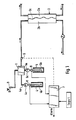
- Fig. 1 an embodiment for a device for hemodialysis according to the invention is shown.
- the device has a mixing device 1 which produces dialysis liquid for a dialyzer 2.
- This dialyzer 2 consists in a known manner of a blood part 2a and a dialysis liquid part 2b, which are separated by a membrane 2c.
- the dialysis fluid is passed through in a known manner Mixture of two dialysis concentrates with treated water produced in the mixing device 1.
- the treated water is withdrawn at 3.
- the concentrates are accommodated in containers 4 and 5, into which the intake pipes 4b, 5b are immersed and which are connected to the assigned concentrate intake plugs on the mixing device 1 via intake hoses 4a and 5a.
- the concentrates are conveyed from the containers 4 and 5 into the mixing device via concentrate pumps 4c and 5c, respectively.
- the concentrate pumps 4c, 5c and the fresh water supply device are controlled by a control device, not shown, which is known from the prior art.
- the so-called “acid concentrate”, an approximately 4-molar acid concentrate solution, is said to be in one concentrate container, and the other container contains a bicarbonate concentrate (1-molar solution).
- the first concentrate in a ratio of 1:35 and the bicarbonate concentrate in a ratio of 1:26 must be added to the finished solution.
- the protection system prevents, in a known manner, dialysis fluid with a composition which is dangerous for the patient from being sent to the dialyzer 2 arrives.
- the suction part 4a, 4b; 5a, 5b each have a conductivity cell 8, 9, the output signal of which is connected to the monitoring stage 7.
- the conductivity of the 1-molar bicarbonate solution and the approx. 4-molar acid concentrate solution differ so much from one another that even after taking into account all the tolerances to be taken into account, there remains a clear difference in conductivity.
- temperature compensation can also be dispensed with, since the deviations caused thereby are only in the order of magnitude of approximately 20-30%.
- mix-ups can be reliably identified, especially those that would lead to a dialysis fluid with a conductivity in the expected range, that is, the higher-level protection system with the measuring cell 6 would not respond because the measured conductivity of the dialysis fluid is in the target range.
- the signal deviations occurring in the monitoring stage can trigger a switching or control process in the mixing device and / or an alarm signal.
- the invention is not restricted to the concentrate example given. It can be used with all concentrates that have a significantly different conductivity to one another.
- the electrodes of the conductivity cells are integrated in the concentrate suction lines so that they can simultaneously serve as level sensors for the concentrate containers.
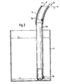
- FIG. 2 shows the concentrate container 4 of FIG. 1 in an enlarged schematic illustration.
- the concentrate container is connected to the mixing device 1 by means of the feed hose 4a.
- the suction pipe 4b which is made of a plastic material and which has the suction opening in the lower region, indicated by the arrows.
- the first electrode 8a of the conductivity cell is attached to the outside of the plastic tube.
- the second electrode 8b is located in the feed tube 4a, which is not immersed in the concentrate solution.
- a measurement signal for the conductivity is set at the terminals 10 as soon as the concentrate liquid column reaches the second electrode 8b. If the level in the container drops below the level of the first electrode 8a, this signal is interrupted and an alarm signal can be generated before the central container is empty.
- Such fill level monitors in the concentrate container are known per se; In the known case, contactless proximity switches are additionally provided for the detection of the fill level. In the case of the invention, however, the simultaneous use of electrodes 8a, b for conductivity measurement and for filling level monitoring is essential.
- FIG. 3 shows a partially sectioned representation of a complete intake pipe which, in contrast to the intake pipe according to FIG. 2, does not have a conductivity cell as such, but in which the conductivity is registered in the monitoring circuit 7 via an electrically conductive metal pipe 11 and its radial outlet openings 12 and is displayed and which also serve as a level meter.
- the supply hose 4a merges into an intermediate clamping piece 13 at its front end, which in turn is connected to the output pipe 4b.
- This transition point is surrounded by a handle 14, which consists of a plastic.
- an electrically conductive metal pipe 11 Over almost the entire area of the suction pipe 4b, this is surrounded by an electrically conductive metal pipe 11, which is also connected at its rear end to the intermediate clamping piece 13 in an electrically insulated manner.
- the electrically conductive metal tube 11 serves as an electrode and is connected to a contact line 15 located in the feed hose 4a via a contact spring 16 arranged in the handle 14.
- the handle 14 is sealed against the metal tube 11 by means of a sealing washer 17 so that no concentrate liquid can get into the interior of the handle 14.
- This sealing washer 17 is fixed by a spacer ring 18.
- a locking element 19 is provided in the handle 14, which can be pivoted via a pin 20 and can be snapped into a handle opening 21.
- the latching element 18 when actuated, it can be removed together with the electrically conductive metal tube 11 from the holder of the handle 14, and another suction tube and / or metal tube can be used.
- each coding socket has a different shape or a different cross section, for example circular or rectangular.
- a corresponding conductivity is registered in the monitoring circuit 7.
- the contact line 15 and the metal tube 11 are live. If the concentrate level now drops below the suction openings 12, there is no longer any conductivity between the concentrate in the liquid container and the metal tube 11, so that the absence of the conductivity is reported via the contact line 15 to the monitoring circuit 7, which generates a corresponding alarm signal before the concentrate container is empty .
- the electrical conductivity thus simultaneously serves to monitor the fill level, since the suction openings 12 at the front end of the metal tube 11 assume the function of a conductivity cell.
Landscapes
- Health & Medical Sciences (AREA)
- Heart & Thoracic Surgery (AREA)
- Urology & Nephrology (AREA)
- Anesthesiology (AREA)
- Vascular Medicine (AREA)
- Engineering & Computer Science (AREA)
- Emergency Medicine (AREA)
- Biomedical Technology (AREA)
- Hematology (AREA)
- Life Sciences & Earth Sciences (AREA)
- Animal Behavior & Ethology (AREA)
- General Health & Medical Sciences (AREA)
- Public Health (AREA)
- Veterinary Medicine (AREA)
- External Artificial Organs (AREA)
Abstract
Description
- Die Erfindung bezieht sich auf eine Vorrichtung für die Hämodialyse mit einer Mischeinrichtung, die Dialysierflüssigkeit für einen Dialysator durch Mischung mindestens eines über eine Ansaugleitung aus einem Behälter zugeführten Dialysekonzentrates mit aufbereitetem Wasser herstellt, und mit einem vom Mischsystem unabhängigen, auf der Überwachung der Leitfähigkeit der Dialysierflüssigkeit beruhenden Schutzsystem, das verhindert, daß Dialysierflüssigkeit mit einer für den Patienten gefährlicher Zusammensetzung zum Dialysator gelangt, wie beispielsweise aus der EP-A 160 272 bekannt.
- Hämodialysegeräte besitzen üblicherweise eine Misch-Einrichtung, die Dialysierflüssigkeit durch Mischung mindestens eines Dialysekonzentrates mit aufbereitetem Wasser für den Dialysator herstellt. Die Misch-Einrichtung besitzt dabei Ansaugstecker für die Ansaugleitungen der Konzentratbehälter.
- Da solche Mischeinrichtungen versagen können, wird durch die gültigen Sicherheitsnormen ein vom Mischsystem unabhängiges Schutzsystem gefordert, das verhindert, daß Dialysierflüssigkeit mit für den Patienten gefährlichen Zusammensetzung zum Dialysator gelangt. Die Kontrolle der Leitfähigkeit der Dialysierflüssigkeit gilt dabei als hinreichendes Schutzsystem (VDE 750/Teil 206).
- Es ist beispielsweise aus der eingangs erwähnten EP-A 160 272 bekannt, ein volumetrisches Mischsystem mit einem unabhängigen Schutzsystem auf der Basis der Leitfähigkeitsüberwachung der Dialysierflüssigkeit zu kombinieren. Dieses System bietet hinreichend Schutz vor der Dialyse mit falscher
Dialysierflüssigkeitszusammensetzung, auch für den Fall eines beliebigen ersten Fehlers. - Aus medizinischen Gründen hat in den letzten Jahren die Hamodialyse mit bicarbonathaltiger Dialysierflüssigkeit Verbreitung gefunden. Aus Gründen der Stabilität muß in diesem Fall die Dialysierflüssigkeit durch Mischung von Wasser mit zwei Konzentraten hergestellt werden.
- Neben den Fällen, daß zwei verschiedene Konzentrate mit unterschiedlichen Mischungsverhältnissen mit Wasser gemischt werden sollen, gibt es auch Misch-Einrichtungen, bei denen nur bestimmtes Konzentrat mit vorgegebenem Mischverhältnis eingemischt wird.
- In der Regel werden die Konzentrate in Behältern (Kanistern) bereitgestellt. Da nun mehrere unterschiedliche Konzentrate in einer Dialysestation vorhanden sind, kann durch Verwechslung von Konzentrat-Behältern eine zusätzliche Gefährdung auftreten. Es wurde gezeigt, daß es Möglichkeiten der Verwechslung gibt, die zu einer für den Patienten gefährlichen Zusammensetzung der Dialysierflüssigkeit führen, die durch das Leitfähigkeits-Schutzsystem nicht erkannt werden können.
- Zur Vermeidung solcher Gefährdungen ist es bekannt, zum Anschluß der Konzentratbehälter an die Ansaugstecker "kodierte Stecker" vorzusehen, die einen unverwechselbaren Anschluß des gewünschten Konzentratbehälters an den zugehörigen Ansaugstecker sicherstellen. Das System der kodierten Stecker setzt jedoch voraus, daß die Mischeinrichtung bzw. das Gerät und die Konzentratbehäter von demselben Hersteller stammen, da insoweit noch keine Normierung vorgenommen worden ist. Die Sicherheit durch kodierte Stecker ist daher nicht mehr gegeben, wenn Konzentratbehälter anderer Bauart vorhanden sind.
- Es ist ferner bekannt, ein Schutzsystem auf pH-Elektrodenbasis vorzusehen.
- Ein solches Schutzsystem hat jedoch nur bedingten Wert, da seine Funktion unter den üblichen Bedingungen des Hämodialysebetriebes nicht wie die übrigen Schutzsysteme vor Beginn einer Hämodialysebehandlung auf Funktion prüfbar ist. Dazu kommt, daß die Lebensdauer von pH-Elektroden unter den Bedingungen der Hämodialyse in der Regel kleiner als ein Jahr sind.
- Der Erfindung liegt die Aufgabe zugrunde, ausgehend von den eingangs bezeichneten Vorrichtungen für die Hämodialyse mit einer Mischeinrichtung, die Dialysierflüssigkeit für einen Dialysator durch Mischung mindestens eines, über eine Ansaugleitung aus einem Behälter zugeführten Dialysekonzentrates mit aufbereitetem Wasser herstellt, und mit einem vom Mischsystem unabhängigen, auf der Überwachung der Leitfähigkeit der Dialysierflüssigkeit beruhenden Schutzsystem, das verhindert, daß Dialysierflüssigkeit mit einer für den Patienten gefährlichen Zusammensetzung zum Dialysator gelangt, diese so auszubilden, daß ein wirksamer Schutz gegen die mit falscher Zusammensetzung der Dialysierflüssigkeit gegen die Verwendung eines falschen Dialysekonzentrats erzielt werden kann.
- Die Lösung dieser Aufgabe gelingt gemäß der Erfindung dadurch, daß in der Ansaugleitung eine zusätzliche Leitfähigkeitszelle angeordnet ist, deren Ausgangssignal auf eine Überwachungsstufe des Schutzsystems geschaltet ist, an der die Soll-Leitfähigkeit bei richtigem Anschluß des Dialyse-Konzentratbehälters voreingestellt ist und die ein Alarm- oder Steuersignal abgibt, wenn die gemessene Leitfähigkeit aufgrund eines falschen Anschlusses des Dialyse-Konzentratbehälters von dem voreingestellten Wert abweicht.
- Da jedes Konzentrat eine spezifische Leitfähigkeit hat, d.h. die Leitfähigkeit das Konzentrat "identifiziert", ist sichergestellt, daß der Anschluß eines falschen Konzentratbehälters sofort erkannt wird.
- Gleiches gilt, wenn zwei Konzentratbehälter mit unterschiedlichen Konzentraten vertauscht angeschlossen wurden.
- Die Erfindung schafft daher ein wirksames Schutzsystem gegen Dialyse mit falscher Zusammensetzung der Dialysierflüssigkeit aufgrund von falsch angeschlossenen Konzentratbehältern.
- Anhand von in den Zeichnungen dargestellten Ausführungsbeispielen wird die Erfindung näher erläutert.
- Es zeigen :
- 1. Fig. 1 eine schematische Darstellung eines Hämodialysegerätes, bei der die Erfindung Anwendung findet,
- 2. Fig. 2 eine schematische Darstellung eines der Konzentratbehälter der Figur 1.
- 3. Fig.3 eine teilweise geschnittene Darstellung einer kompletten Ausgangsrohrleitung.
- In Fig. 1 ist eine Ausführungsform für eine Vorrichtung für die Hämodialyse nach der Erfindung dargestellt. Die Vorrichtung weist eine Mischeinrichtung 1 auf, die Dialysierflüssigkeit für einen Dialysator 2 herstellt. Dieser Dialysator 2 besteht in bekannter Weise aus einem Blutteil 2a und einem Dialysierflüssigkeitsteil 2b, die durch eine Membran 2c abgetrennt sind.
- Die Dialysierflüssigkeit wird in bekannter Weise durch Mischung von zwei Dialysekonzentraten mit aufbereitetem Wasser in der Mischeinrichtung 1 hergestellt. Das aufbereitete Wasser wird bei 3 entnommen. Die Konzentrate sind in Behältern 4 und 5 untergebracht, in die Ansaugrohre 4b, 5b eintauchen und die über Ansaug-Schläuche 4a und 5a mit den zugeordneten Konzentratansaugsteckern an der Mischeinrichtung 1 verbunden sind.
- Die Konzentrate werden aus den Behältern 4 und 5 jeweils über Konzentratpumpen 4c und 5c in die Mischeinrichtung gefördert. Die Konzentratpumpen 4c, 5c sowie die Frischwasserzuführungseinrichtung werden von einer nicht gezeigten Steuereinrichtung gesteuert, was aus dem Stand der Technik bekannt ist.
- In einem Konzentratbehälter soll sich beispielsweise das sogenannte "Säurekonzentrat", eine ca. 4-molare Säurekonzentratlösung, in dem anderen Behälter ein Bicarbonatkonzentrat (1-molare Lösung) befinden. Um die richtige Zusammensetzung der Dialysierflüssigkeit zu erhalten, muß das erste Konzentrat im Verhältnis 1 : 35, das Bicarbonatkonzentrat im Verhältnis 1 : 26 zur fertigen Lösung zugemischt werden.
- Da auf einer Dialysestation unterschiedliche Konzentrate vorhanden sind, kann durch eine Verwechslung von Konzentraten insoweit eine zusätzliche Gefährdung auftreten.
- Mit 6 ist ein Leitfähigkeitsmeßgerät eines vom Mischsystem unabhängigen Schutzsystems bezeichnet, dessen Ausgangssignal auf eine Überwachungsschaltung 7 geschaltet ist. Das Schutzsystem verhindert in bekannter Weise, daß Dialysierflüssigkeit mit für den Patienten gefährlicher Zusammensetzung zum Dialysator 2 gelangt.
- Es wurde jedoch angezeigt, daß es Möglichkeiten der Verwechslung von Konzentratbehältern gibt, die zu einer für den Patienten gefährlichen Zusammensetzung der Dialysierflüssigkeit führen, die durch das Leitfähigkeitsschutzsystem mit der Zelle 6 nicht erkannt werden können.
- Um diese zusätzliche Gefährdung wirksam auszuschließen, ist in dem Ansaugteil 4a, 4b; 5a, 5b jeweils eine Leitfähigkeitszelle 8, 9 angeordnet, deren Ausgangssignal auf die Überwachungsstufe 7 geschaltet ist. Die Leitfähigkeit der 1-molaren Bicarbonatlösung und der ca. 4-molaren Säurekonzentratlösung unterscheiden sich voneinander so stark, daß selbst nach Berücksichtigung aller einzubeziehenden Toleranzen ein deutlicher Leitfähigkeitsunterschied bleibt. So kann z.B. auch auf eine Temperaturkompensation verzichtet werden, da die dadurch hervorgerufenen Abweichungen nur in der Größenordnung von etwa 20 - 30 % liegen.
- Wertet man statt der Absolutleitfähigkeit des einzelnen Konzentrates deren Verhältnis aus, so sinkt der Einfluß unterschiedlicher Temperaturen auf wenige % unter der Annahme, daß beide Konzentrate dieselbe Temperatur haben, was in der Regel gegeben ist.
- Durch Vergleich der von den Leitfähigkeitszellen abgegebenen Ausgangssignale mit den voreingestellten Soll-Leitfähigkeitswerten können daher Konzentratverwechslungen sicher erkannt werden, insbesondere jene, die zu einer Dialysierflüssigkeit mit einer Leitfähigkeit im Erwartungsbereich führen würden, d.h. die das übergeordnete Schutzsystem mit der Meßzelle 6 nicht ansprechen lassen würden, weil die gemessene Leitfähigkeit der Dialysierflüssigkeit im Sollbereich liegt.
- Die auftretenden Signal-Abweichungen in der Überwachungsstufe können einen Schalt- bzw. Steuervorgang in der Mischeinrichtung und/oder ein Alarmsignal auslösen.
- Das Ziel einer einfachen und sicheren Schutzanordnung gegen Konzentratverwechslungen ist somit erreicht.
- Die Erfindung ist nicht auf das angegebene Konzentratbeispiel beschränkt. Sie kann Anwendung finden bei allen Konzentraten, die eine deutlich unterschiedliche Leitfähigkeit zueinander aufweisen.
- Es ist auch möglich, mit dem erfindungsgemäßen Prinzip solche Mischeinrichtungen zusätzlich zu überwachen, die nur einen Konzentratansaugstecker haben. Der jeweils gemessene Leitfähigkeitswert des angeschlossenen Konzentrates wird dann mit dem in der Überwachungsstufe eingestellten Sollwert des Leitfähigkeitswertes des tatsächlich auszuschließenden Konzentrates verglichen.
- Nach einer vorteilhaften Ausgestaltung der Erfindung, die in Fig. 2 dargestellt ist, werden die Elektroden der Leitfähigkeitszellen in den Konzentratansaugleitungen so integriert, daß sie gleichzeitig als Füllstandssensoren für die Konzentratbehälter dienen können.
- Die Fig. 2 zeigt den Konzentratbehälter 4 der Fig. 1 in vergrößerter schematischer Darstellung. Der Konzentratbehälter ist mittels des Zuführschlauches 4a an die Mischeinrichtung 1 angeschlossen. In das Konzentrat taucht das Ansaugrohr 4b ein, das aus einem Kunststoffmaterial hergestellt ist und das im unteren Bereich, angedeutet durch die Pfeile, die Ansaugöffnung besitzt. Oberhalb dieser Ansaugöffnungen ist an der Außenseite des Kunststoffrohres die erste Elektrode 8a der Leitfähigkeitszelle angebracht. Die zweite Elektrode 8b befindet sich im Zuführschlauch 4a, der nicht in die Konzentratlösung eintaucht.
- Wird im Betrieb Konzentrat in das Innere des Ansaugrohres 4b angesaugt, so stellt sich an den Klemmen 10 ein Meßsignal für die Leitfähigkeit ein, sobald die Konzentratflüssigkeitssäule die zweite Elektrode 8b erreicht. Sinkt der Füllstand im Behälter unter das Niveau der ersten Elektrode 8a, so wird dieses Signal unterbrochen und es kann ein Alarmsignal erzeugt werden, bevor der Konzentralbehälter leer ist.
- Derartige Füllstandsüberwachungen im Konzentratbehälter sind an sich bekannt; im bekannten Fall werden kontaktlose Nährungsschalter für die Erfassung des Füllstandes zusätzlich vorgesehen. Im Fall der Erfindung ist jedoch die gleichzeitige Verwendung der Elektroden 8a, b zur Leitfähigkeitsmessung und zur Füllstandsüberwachung wesentlich.
- Die Fig. 3 zeigt eine teilweise geschnittene Darstellung eines kompletten Ansaugrohres, die im Unterschied zur Ansaugrohrleitung gemäß Fig.2 keine Leitfähigkeitszelle als solche aufweist, sondern bei der die Leitfähigkeit über ein elektrisch leitendes Metallrohr 11 und dessen radiale Ausgangsöffnungen 12 in der Überwachungsschaltung 7 registriert und angezeigt wird und die gleichzeitig als Füllstandsmesser dienen. Entsprechend dieser Ausführungsform geht der Zuführschlauch 4a an seinem vorderen Ende in ein Zwischenklemmstück 13 über, welches wiederum mit dem Ausgangsrohr 4b verbunden ist. Diese Übergangsstelle ist von einem Griffstück 14 umgeben, das aus einem Kunststoff besteht. Über nahezu den gesamten Bereich des Ansaugrohres 4b ist dieses von einem elektrisch leitenden Metallrohr 11 umhüllt, das an seinem hinteren Ende ebenfalls mit dem Zwischenklemmstück 13 elektrisch isoliert verbunden ist. Das elektrisch leitende Metallrohr 11 dient als Elektrode und ist mit einer im Zuführschlauch 4a befindlichen Kontaktleitung 15 über eine im Griffstück 14 angeordnete Kontaktfeder 16 in Verbindung. Das Griffstück 14 ist gegenüber dem Metallrohr 11 mittels einer Dichtscheibe 17 konzentratmitteldicht abgedichtet, damit keine Konzentratflüssigkeit in den Innenraum des Griffstückes 14 gelangen kann. Diese Dichtscheibe 17 ist durch einen Distanzring 18 festgelegt.
- Weiterhin ist im Griffstück 14 ein Rastelement 19 vorgesehen, das über einen Stift 20 schwenkbar und in eine Grifföffnung 21 einrastbar ist. Dadurch kann bei Betätigung des Rastelementes 18 dieses zusammen mit dem elektrisch leitenden Metallrohr 11 aus der Halterung des Griffstückes 14 beliebig entfernt und ein anderes Ansaugrohr und/oder Metallrohr eingesetzt werden.
- Am vorderen Ende des Metallrohres 11 im Bereich der Ansaugöffnungen 12, die O-ringförmig ausgebildet sein können und eine Strömungsverbindung vom Außenraum zum Innenraum des Ansaugrohres 4b gewährleisten, erstreckt sich ein Teil des Ansaugrohres 4b, an dem eine Codierbuchse 22 angeordnet ist, die das vordere Ende des Ansaugrohres 4b verschließt. Diese dient dazu, in ein im Konzentratbehälter angebrachtes entsprechendes Gegenstück einzugreifen, um eine Verwechslung der Konzentratbehälter mit dem entsprechenden Zuführschlauch auszuschließen. Dazu weist jede Codierbuchse eine andere Form oder einen anderen Querschnitt, beispielsweise kreis- oder rechteckigförmig auf.
- In der Überwachungsschaltung 7 ist eine entsprechende Leitfähigkeit registriert. Die Kontaktleitung 15 und das Metallrohr 11 sind stromführend. Sinkt nun der Konzentratspiegel unterhalb der Ansaugöffnungen 12, besteht keine Leitfähigkeit mehr zwischen dem Konzentrat im Flüssigkeitsbehälter und dem Metallrohr 11, so daß das Nichtvorhandensein der Leitfähigkeit über die Kontaktleitung 15 an die Überwachungsschaltung 7 gemeldet wird, die ein entsprechendes Alarmsignal erzeugt bevor der Konzentratbehälter leer ist. Damit dient die elektrische Leitfähigkeit gleichzeitig der Füllstandsüberwachung, da die Ansaugöffnungen 12 am vorderen Ende des Metallrohres 11 die Funktion einer Leitfähigkeitszelle übernehmen.
Claims (8)
Applications Claiming Priority (2)
| Application Number | Priority Date | Filing Date | Title |
|---|---|---|---|
| DE3734880A DE3734880C1 (de) | 1987-10-15 | 1987-10-15 | Vorrichtung fuer die Haemodialyse mit Schutzsystem gegen falsche Zusammensetzung der Dialysierfluessigkeit |
| DE3734880 | 1987-10-15 |
Publications (3)
| Publication Number | Publication Date |
|---|---|
| EP0311848A2 true EP0311848A2 (de) | 1989-04-19 |
| EP0311848A3 EP0311848A3 (en) | 1990-07-25 |
| EP0311848B1 EP0311848B1 (de) | 1993-02-03 |
Family
ID=6338368
Family Applications (1)
| Application Number | Title | Priority Date | Filing Date |
|---|---|---|---|
| EP88116103A Expired - Lifetime EP0311848B1 (de) | 1987-10-15 | 1988-09-29 | Hämodialysegerät mit Schutzsystem gegen falsche Zusammensetzung der Dialysierflüssigkeit |
Country Status (5)
| Country | Link |
|---|---|
| US (1) | US4895657A (de) |
| EP (1) | EP0311848B1 (de) |
| JP (1) | JP2769503B2 (de) |
| DE (2) | DE3734880C1 (de) |
| ES (1) | ES2038730T3 (de) |
Cited By (20)
| Publication number | Priority date | Publication date | Assignee | Title |
|---|---|---|---|---|
| WO1992005814A1 (en) * | 1990-09-28 | 1992-04-16 | Baxter International Inc. | Method and apparatus for preparation of solutions from concentrates |
| EP0947206A3 (de) * | 1998-04-01 | 1999-12-15 | Fresenius Medical Care Deutschland GmbH | Dialysegerät mit Vorrichtung zur Herstellung von Dialyselösungen |
| EP2258419A3 (de) * | 1998-04-01 | 2011-03-09 | Fresenius Medical Care Deutschland GmbH | Dialysegerät mit Vorrichtung zur Herstellung von Dialyselösungen |
| US7981281B2 (en) | 2008-07-09 | 2011-07-19 | Baxter International, Inc. | Dialysis system having regimen generation methodology |
| US8057679B2 (en) | 2008-07-09 | 2011-11-15 | Baxter International Inc. | Dialysis system having trending and alert generation |
| US8062513B2 (en) | 2008-07-09 | 2011-11-22 | Baxter International Inc. | Dialysis system and machine having therapy prescription recall |
| US8168063B2 (en) | 2008-07-09 | 2012-05-01 | Baxter International Inc. | Dialysis system having filtering method for determining therapy prescriptions |
| US9713664B2 (en) | 2013-03-15 | 2017-07-25 | Fresenius Medical Care Holdings, Inc. | Nuclear magnetic resonance module for a dialysis machine |
| US9772386B2 (en) | 2013-03-15 | 2017-09-26 | Fresenius Medical Care Holdings, Inc. | Dialysis system with sample concentration determination device using magnet and radio frequency coil assemblies |
| WO2018024373A1 (de) * | 2016-08-03 | 2018-02-08 | Fresenius Medical Care Deutschland Gmbh | Verfahren zur überwachung des bicarbonat-gehalts und des natrium-gehalts einer dialyselösung |
| US10286135B2 (en) | 2014-03-28 | 2019-05-14 | Fresenius Medical Care Holdings, Inc. | Measuring conductivity of a medical fluid |
| US10293091B2 (en) | 2007-07-05 | 2019-05-21 | Baxter International Inc. | Dialysis system having an autoconnection mechanism |
| US10314958B2 (en) | 2009-05-20 | 2019-06-11 | Baxter International Inc. | System and method for pairing a dialysis machine with peripheral devices |
| US10371775B2 (en) | 2013-03-15 | 2019-08-06 | Fresenius Medical Care Holdings, Inc. | Dialysis system with radio frequency device within a magnet assembly for medical fluid sensing and concentration determination |
| US10451572B2 (en) | 2013-03-15 | 2019-10-22 | Fresenius Medical Care Holdings, Inc. | Medical fluid cartridge with related systems |
| US10561780B2 (en) | 2008-07-09 | 2020-02-18 | Baxter International Inc. | Dialysis system having inventory management including online dextrose mixing |
| US11135345B2 (en) | 2017-05-10 | 2021-10-05 | Fresenius Medical Care Holdings, Inc. | On demand dialysate mixing using concentrates |
| DE102020126224A1 (de) | 2020-10-07 | 2022-04-07 | Fresenius Medical Care Deutschland Gmbh | Zugangssystem für ein medizintechnisches Gerät zur Entnahme einer medizinischen Flüssigkeit und Überwachungssystem mit einem derartigen Zugangssystem und ein medizinisches Behandlungsgerät mit einem derartigen Überwachungssystem |
| US11504458B2 (en) | 2018-10-17 | 2022-11-22 | Fresenius Medical Care Holdings, Inc. | Ultrasonic authentication for dialysis |
| WO2025209681A1 (de) * | 2024-04-02 | 2025-10-09 | Fresenius Medical Care Deutschland Gmbh | Dialysemaschine mit einem mischsystem zur herstellung einer dialyselösung |
Families Citing this family (30)
| Publication number | Priority date | Publication date | Assignee | Title |
|---|---|---|---|---|
| DE3930181A1 (de) * | 1989-09-09 | 1991-03-21 | Fresenius Ag | Druckausgleichsgefaess fuer ein haemodialysekonzentrat |
| US5762798A (en) * | 1991-04-12 | 1998-06-09 | Minntech Corporation | Hollow fiber membranes and method of manufacture |
| US5486286A (en) | 1991-04-19 | 1996-01-23 | Althin Medical, Inc. | Apparatus for performing a self-test of kidney dialysis membrane |
| US6139754A (en) * | 1991-11-15 | 2000-10-31 | Baxter International Inc. | Hemodialysis conductivity servo-proportioning system and method |
| DE4138140C2 (de) * | 1991-11-20 | 1993-12-23 | Fresenius Ag | Vorrichtung zur Desinfektion von Hämodialysegeräten mit einem pulverförmigen Konzentrat |
| DE4139165C2 (de) * | 1991-11-28 | 1994-12-08 | Fresenius Ag | Einrichtung zur Herstellung einer medizinischen Flüssigkeit |
| US5278149A (en) * | 1992-01-17 | 1994-01-11 | New England Deaconess Hospital Corporation | Method of preparing total parenteral nutrition solutions |
| USRE36914E (en) * | 1992-10-07 | 2000-10-17 | Minntech Corp | Dialysate filter including an asymmetric microporous, hollow fiber membrane incorporating a polyimide |
| DE10302691B3 (de) | 2003-01-24 | 2004-04-29 | Fresenius Medical Care Deutschland Gmbh | Verfahren und Vorrichtung zur Versorgung einer Dialysevorrichtung mit Dialysierflüssigkeit |
| US8029454B2 (en) | 2003-11-05 | 2011-10-04 | Baxter International Inc. | High convection home hemodialysis/hemofiltration and sorbent system |
| CN101237918B (zh) * | 2005-05-17 | 2013-01-09 | 弗雷塞尼斯医疗保健控股公司 | 血液透析方法和设备 |
| US8870811B2 (en) | 2006-08-31 | 2014-10-28 | Fresenius Medical Care Holdings, Inc. | Peritoneal dialysis systems and related methods |
| AU2008260230B2 (en) | 2007-05-29 | 2013-09-19 | Fresenius Medical Care Holdings, Inc. | Solutions, dialysates, and related methods |
| US8157761B2 (en) | 2007-07-05 | 2012-04-17 | Baxter International Inc. | Peritoneal dialysis patient connection system |
| US8330579B2 (en) | 2007-07-05 | 2012-12-11 | Baxter International Inc. | Radio-frequency auto-identification system for dialysis systems |
| US8764702B2 (en) | 2007-07-05 | 2014-07-01 | Baxter International Inc. | Dialysis system having dual patient line connection and prime |
| US7955295B2 (en) | 2007-07-05 | 2011-06-07 | Baxter International Inc. | Fluid delivery system with autoconnect features |
| US8197087B2 (en) | 2007-07-05 | 2012-06-12 | Baxter International Inc. | Peritoneal dialysis patient connection system using ultraviolet light emitting diodes |
| US7736328B2 (en) | 2007-07-05 | 2010-06-15 | Baxter International Inc. | Dialysis system having supply container autoconnection |
| US7892197B2 (en) | 2007-09-19 | 2011-02-22 | Fresenius Medical Care Holdings, Inc. | Automatic prime of an extracorporeal blood circuit |
| US8926551B2 (en) | 2009-07-07 | 2015-01-06 | Baxter Healthcare Inc. | Peritoneal dialysis therapy with large dialysis solution volumes |
| JP5423318B2 (ja) * | 2009-10-29 | 2014-02-19 | ニプロ株式会社 | 透析液の濃度監視装置およびその作動方法 |
| US9585810B2 (en) | 2010-10-14 | 2017-03-07 | Fresenius Medical Care Holdings, Inc. | Systems and methods for delivery of peritoneal dialysis (PD) solutions with integrated inter-chamber diffuser |
| DE102011016167A1 (de) * | 2011-04-05 | 2012-12-27 | Ritter Gmbh | Behälter aus Kunststoff für die Dialyse |
| US9566377B2 (en) | 2013-03-15 | 2017-02-14 | Fresenius Medical Care Holdings, Inc. | Medical fluid sensing and concentration determination in a fluid cartridge with multiple passageways, using a radio frequency device situated within a magnetic field |
| CN104379189B (zh) * | 2013-04-25 | 2016-10-12 | 甘布罗伦迪亚股份公司 | 医疗流体制备系统和方法 |
| EP3505199B1 (de) * | 2017-12-28 | 2020-04-01 | Gambro Lundia AB | Vorrichtung zur extrakorporalen behandlung von blut |
| DE102020104101A1 (de) | 2020-02-17 | 2021-08-19 | Fresenius Medical Care Deutschland Gmbh | Fluidflusssteuerung einer Blutbehandlungsvorrichtung |
| DE102023113697A1 (de) | 2023-05-25 | 2024-11-28 | B.Braun Avitum Ag | Vorrichtung zur extrakorporalen Blutbehandlung |
| DE102023117587A1 (de) * | 2023-07-04 | 2025-01-09 | Fresenius Medical Care Deutschland Gmbh | Zusammensetzung für Dialyselösung und Sensorikeinheit |
Family Cites Families (5)
| Publication number | Priority date | Publication date | Assignee | Title |
|---|---|---|---|---|
| US4150673A (en) * | 1977-02-03 | 1979-04-24 | Pharmachem Corporation | Coded entry system for blood bag |
| DE3416057A1 (de) * | 1984-04-30 | 1985-10-31 | Fresenius AG, 6380 Bad Homburg | Haemodialysevorrichtung |
| DE3443911C2 (de) * | 1984-12-01 | 1994-06-01 | Andreas Alexander Dr Med Mund | Einrichtung zum Herstellen von flüssigem Konzentrat aus pulverförmigem Konzentratsalz für die Zubereitung von Dialysierflüssigkeit |
| US4718022A (en) * | 1985-02-21 | 1988-01-05 | Cochran Michael J | Dialysis machine which anticipates concentration changes |
| US4739492A (en) * | 1985-02-21 | 1988-04-19 | Cochran Michael J | Dialysis machine which verifies operating parameters |
-
1987
- 1987-10-15 DE DE3734880A patent/DE3734880C1/de not_active Expired
-
1988
- 1988-09-29 DE DE8888116103T patent/DE3878132D1/de not_active Expired - Lifetime
- 1988-09-29 ES ES198888116103T patent/ES2038730T3/es not_active Expired - Lifetime
- 1988-09-29 EP EP88116103A patent/EP0311848B1/de not_active Expired - Lifetime
- 1988-10-05 US US07/253,814 patent/US4895657A/en not_active Expired - Lifetime
- 1988-10-14 JP JP63259263A patent/JP2769503B2/ja not_active Expired - Lifetime
Cited By (37)
| Publication number | Priority date | Publication date | Assignee | Title |
|---|---|---|---|---|
| WO1992005814A1 (en) * | 1990-09-28 | 1992-04-16 | Baxter International Inc. | Method and apparatus for preparation of solutions from concentrates |
| EP0947206A3 (de) * | 1998-04-01 | 1999-12-15 | Fresenius Medical Care Deutschland GmbH | Dialysegerät mit Vorrichtung zur Herstellung von Dialyselösungen |
| US6468424B1 (en) | 1998-04-01 | 2002-10-22 | Fresenius Medical Care Deutschland Gmbh | Connector adapted to connect a storage container for solution ingredients to a medical apparatus |
| US6685831B2 (en) * | 1998-04-01 | 2004-02-03 | Fresenius Medical Care Deutschland Gmbh | Dialysis machine with a device for preparing dialysis solutions |
| EP2258419A3 (de) * | 1998-04-01 | 2011-03-09 | Fresenius Medical Care Deutschland GmbH | Dialysegerät mit Vorrichtung zur Herstellung von Dialyselösungen |
| US10293091B2 (en) | 2007-07-05 | 2019-05-21 | Baxter International Inc. | Dialysis system having an autoconnection mechanism |
| US10016554B2 (en) | 2008-07-09 | 2018-07-10 | Baxter International Inc. | Dialysis system including wireless patient data |
| US12564665B2 (en) | 2008-07-09 | 2026-03-03 | Vantive Us Healthcare Llc | Dialysis apparatus including therapy prescription selection |
| US8168063B2 (en) | 2008-07-09 | 2012-05-01 | Baxter International Inc. | Dialysis system having filtering method for determining therapy prescriptions |
| US8257582B2 (en) | 2008-07-09 | 2012-09-04 | Baxter International Inc. | Dialysis system and machine having therapy prescription recall |
| US8313642B2 (en) | 2008-07-09 | 2012-11-20 | Baxter International Inc. | Dialysis system including wireless patient data and trending and alert generation |
| US8512554B2 (en) | 2008-07-09 | 2013-08-20 | Baxter International Inc. | Dialysis system and machine having therapy prescription recall |
| US9141760B2 (en) | 2008-07-09 | 2015-09-22 | Baxter International Inc. | System and method for selection of stored dialysis therapy prescriptions |
| US9149570B2 (en) | 2008-07-09 | 2015-10-06 | Baxter International Inc. | Dialysis system having filtering method for determining therapy prescriptions |
| US9690905B2 (en) | 2008-07-09 | 2017-06-27 | Baxter International Inc. | Dialysis treatment prescription system and method |
| US10561780B2 (en) | 2008-07-09 | 2020-02-18 | Baxter International Inc. | Dialysis system having inventory management including online dextrose mixing |
| US10307524B2 (en) | 2008-07-09 | 2019-06-04 | Baxter International Inc. | Dialysis method and system including wireless patient data |
| US7981281B2 (en) | 2008-07-09 | 2011-07-19 | Baxter International, Inc. | Dialysis system having regimen generation methodology |
| US8057679B2 (en) | 2008-07-09 | 2011-11-15 | Baxter International Inc. | Dialysis system having trending and alert generation |
| US10265455B2 (en) | 2008-07-09 | 2019-04-23 | Baxter International Inc. | Dialysis system including wireless sensor data |
| US10272190B2 (en) | 2008-07-09 | 2019-04-30 | Baxter International Inc. | Renal therapy system including a blood pressure monitor |
| US8062513B2 (en) | 2008-07-09 | 2011-11-22 | Baxter International Inc. | Dialysis system and machine having therapy prescription recall |
| US11027053B2 (en) | 2009-05-20 | 2021-06-08 | Baxter International Inc. | Method for pairing a dialysis machine with peripheral devices |
| US10314958B2 (en) | 2009-05-20 | 2019-06-11 | Baxter International Inc. | System and method for pairing a dialysis machine with peripheral devices |
| US12311087B2 (en) | 2009-05-20 | 2025-05-27 | Baxter International Inc. | System for automated collection of dialysis data |
| US9772386B2 (en) | 2013-03-15 | 2017-09-26 | Fresenius Medical Care Holdings, Inc. | Dialysis system with sample concentration determination device using magnet and radio frequency coil assemblies |
| US10371775B2 (en) | 2013-03-15 | 2019-08-06 | Fresenius Medical Care Holdings, Inc. | Dialysis system with radio frequency device within a magnet assembly for medical fluid sensing and concentration determination |
| US10451572B2 (en) | 2013-03-15 | 2019-10-22 | Fresenius Medical Care Holdings, Inc. | Medical fluid cartridge with related systems |
| US9713664B2 (en) | 2013-03-15 | 2017-07-25 | Fresenius Medical Care Holdings, Inc. | Nuclear magnetic resonance module for a dialysis machine |
| US10286135B2 (en) | 2014-03-28 | 2019-05-14 | Fresenius Medical Care Holdings, Inc. | Measuring conductivity of a medical fluid |
| US11000638B2 (en) | 2016-08-03 | 2021-05-11 | Fresenius Medical Care Deutschland Gmbh | Method of monitoring the bicarbonate content and the sodium content of a dialysis solution |
| WO2018024373A1 (de) * | 2016-08-03 | 2018-02-08 | Fresenius Medical Care Deutschland Gmbh | Verfahren zur überwachung des bicarbonat-gehalts und des natrium-gehalts einer dialyselösung |
| US11135345B2 (en) | 2017-05-10 | 2021-10-05 | Fresenius Medical Care Holdings, Inc. | On demand dialysate mixing using concentrates |
| US11752246B2 (en) | 2017-05-10 | 2023-09-12 | Fresenius Medical Care Holdings, Inc. | On demand dialysate mixing using concentrates |
| US11504458B2 (en) | 2018-10-17 | 2022-11-22 | Fresenius Medical Care Holdings, Inc. | Ultrasonic authentication for dialysis |
| DE102020126224A1 (de) | 2020-10-07 | 2022-04-07 | Fresenius Medical Care Deutschland Gmbh | Zugangssystem für ein medizintechnisches Gerät zur Entnahme einer medizinischen Flüssigkeit und Überwachungssystem mit einem derartigen Zugangssystem und ein medizinisches Behandlungsgerät mit einem derartigen Überwachungssystem |
| WO2025209681A1 (de) * | 2024-04-02 | 2025-10-09 | Fresenius Medical Care Deutschland Gmbh | Dialysemaschine mit einem mischsystem zur herstellung einer dialyselösung |
Also Published As
| Publication number | Publication date |
|---|---|
| EP0311848B1 (de) | 1993-02-03 |
| DE3734880C1 (de) | 1989-03-23 |
| DE3878132D1 (de) | 1993-03-18 |
| JPH01145068A (ja) | 1989-06-07 |
| EP0311848A3 (en) | 1990-07-25 |
| JP2769503B2 (ja) | 1998-06-25 |
| US4895657A (en) | 1990-01-23 |
| ES2038730T3 (es) | 1993-08-01 |
Similar Documents
| Publication | Publication Date | Title |
|---|---|---|
| EP0311848B1 (de) | Hämodialysegerät mit Schutzsystem gegen falsche Zusammensetzung der Dialysierflüssigkeit | |
| DE19801768C2 (de) | Verfahren und Vorrichtung zur Bereitstellung betriebsbereiter Dialysierflüssigkeit | |
| DE69109850T2 (de) | Apparat zur herstellung von lösungen aus konzentraten. | |
| DE3736712C2 (de) | Dialysat-Zubereitungs- und Versorgungsgerät | |
| EP0367252B1 (de) | Verfahren und Vorrichtung zur Ultrafiltration bei der Hämodialyse | |
| DE69530055T2 (de) | System und Verfahren zum Versetzen einer Flüssigkeit zwischen einem Behälter und einem zugeordneten Apparat zur Verwendung der Flüssigkeit | |
| EP0543283A1 (de) | Vorrichtung zur Desinfektion von Hämodialysegeräten | |
| DE3442744A1 (de) | Dialysegeraet mit einer einrichtung zur wiederverwendung von haemodialysatoren | |
| DE102012103010A1 (de) | Verfahren und Vorrichtung zur Bestimmung der Zusammensetzung medizinischer Flüssigkeiten bezüglich ihres Anteils an Elektrolyten und Nichtelektrolyten | |
| DE3400263C2 (de) | ||
| WO2016169642A1 (de) | Verfahren und vorrichtung zur herstellung einer medizinischen lösung | |
| EP4003449B1 (de) | Dialysegerät mit einer vorrichtung zur identifikation eines dialysators und verfahren zur identifikation eines dialysators | |
| EP3570902A1 (de) | Dialysatkonzentration-messsensordiagnose | |
| EP3493861B1 (de) | Verfahren zur überwachung des bicarbonat-gehalts und des natrium-gehalts einer dialyselösung | |
| DE3639797C1 (en) | Method and device for monitoring the correct composition of dialysis solution, in particular for bicarbonate dialysis | |
| DE3736716A1 (de) | Steuerungseinrichtung fuer die reinigung einer dialysatzubereitungseinrichtung | |
| DE3204520A1 (de) | Dosiersystem, insbesondere fuer kuenstliche nieren | |
| DE2858205C2 (de) | Vorrichtung zur Hämodialyse und zum Entziehen von Ultrafiltrat | |
| DE102006060611B4 (de) | Anordnung zum Anschluss eines medizintechnischen Gerätes an eine Wasserleitung | |
| DE3120773A1 (de) | Verfahren zum reinigen einer membranartigen selektiven matrix bei einer ionenselektiven messelektrode und anordnung zur durchfuehrung dieses verfahrens | |
| DE2364824A1 (de) | Vorrichtung zur automatischen zubereitung einer loesung mit einstellbarer, gesteuerter konzentration, die als dialysefluessigkeit fuer kuenstliche nieren dient | |
| EP3875950A1 (de) | Bestimmung von chlorat mit einer elektrode sowie verfahren und vorrichtung zur kalibrierung der elektrode | |
| EP0219800A2 (de) | Mischvorrichtung für Flüssigkeiten | |
| DE3736711C2 (de) | ||
| EP3648813B1 (de) | Vorrichtung zur erkennung des konnektionszustandes |
Legal Events
| Date | Code | Title | Description |
|---|---|---|---|
| PUAI | Public reference made under article 153(3) epc to a published international application that has entered the european phase |
Free format text: ORIGINAL CODE: 0009012 |
|
| AK | Designated contracting states |
Kind code of ref document: A2 Designated state(s): DE ES FR GB IT SE |
|
| PUAL | Search report despatched |
Free format text: ORIGINAL CODE: 0009013 |
|
| RHK1 | Main classification (correction) |
Ipc: A61M 1/16 |
|
| AK | Designated contracting states |
Kind code of ref document: A3 Designated state(s): DE ES FR GB IT SE |
|
| 17P | Request for examination filed |
Effective date: 19900901 |
|
| 17Q | First examination report despatched |
Effective date: 19910917 |
|
| GRAA | (expected) grant |
Free format text: ORIGINAL CODE: 0009210 |
|
| AK | Designated contracting states |
Kind code of ref document: B1 Designated state(s): DE ES FR GB IT SE |
|
| REF | Corresponds to: |
Ref document number: 3878132 Country of ref document: DE Date of ref document: 19930318 |
|
| ET | Fr: translation filed | ||
| GBT | Gb: translation of ep patent filed (gb section 77(6)(a)/1977) |
Effective date: 19930219 |
|
| ITF | It: translation for a ep patent filed | ||
| REG | Reference to a national code |
Ref country code: ES Ref legal event code: FG2A Ref document number: 2038730 Country of ref document: ES Kind code of ref document: T3 |
|
| PLBE | No opposition filed within time limit |
Free format text: ORIGINAL CODE: 0009261 |
|
| STAA | Information on the status of an ep patent application or granted ep patent |
Free format text: STATUS: NO OPPOSITION FILED WITHIN TIME LIMIT |
|
| 26N | No opposition filed | ||
| EAL | Se: european patent in force in sweden |
Ref document number: 88116103.8 |
|
| REG | Reference to a national code |
Ref country code: GB Ref legal event code: IF02 |
|
| PGFP | Annual fee paid to national office [announced via postgrant information from national office to epo] |
Ref country code: ES Payment date: 20070925 Year of fee payment: 20 |
|
| PGFP | Annual fee paid to national office [announced via postgrant information from national office to epo] |
Ref country code: GB Payment date: 20070921 Year of fee payment: 20 |
|
| PGFP | Annual fee paid to national office [announced via postgrant information from national office to epo] |
Ref country code: IT Payment date: 20070925 Year of fee payment: 20 Ref country code: SE Payment date: 20070924 Year of fee payment: 20 Ref country code: DE Payment date: 20071128 Year of fee payment: 20 |
|
| PGFP | Annual fee paid to national office [announced via postgrant information from national office to epo] |
Ref country code: FR Payment date: 20070926 Year of fee payment: 20 |
|
| REG | Reference to a national code |
Ref country code: GB Ref legal event code: PE20 Expiry date: 20080928 |
|
| EUG | Se: european patent has lapsed | ||
| REG | Reference to a national code |
Ref country code: ES Ref legal event code: FD2A Effective date: 20080930 |
|
| PG25 | Lapsed in a contracting state [announced via postgrant information from national office to epo] |
Ref country code: GB Free format text: LAPSE BECAUSE OF EXPIRATION OF PROTECTION Effective date: 20080928 |
|
| PG25 | Lapsed in a contracting state [announced via postgrant information from national office to epo] |
Ref country code: ES Free format text: LAPSE BECAUSE OF EXPIRATION OF PROTECTION Effective date: 20080930 |