EP0312005B1 - Chauffage par radiation - Google Patents
Chauffage par radiation Download PDFInfo
- Publication number
- EP0312005B1 EP0312005B1 EP88116924A EP88116924A EP0312005B1 EP 0312005 B1 EP0312005 B1 EP 0312005B1 EP 88116924 A EP88116924 A EP 88116924A EP 88116924 A EP88116924 A EP 88116924A EP 0312005 B1 EP0312005 B1 EP 0312005B1
- Authority
- EP
- European Patent Office
- Prior art keywords
- combustion chamber
- intake
- chamber
- combustion
- heat
- Prior art date
- Legal status (The legal status is an assumption and is not a legal conclusion. Google has not performed a legal analysis and makes no representation as to the accuracy of the status listed.)
- Expired - Lifetime
Links
Images


Classifications
-
- F—MECHANICAL ENGINEERING; LIGHTING; HEATING; WEAPONS; BLASTING
- F24—HEATING; RANGES; VENTILATING
- F24C—DOMESTIC STOVES OR RANGES ; DETAILS OF DOMESTIC STOVES OR RANGES, OF GENERAL APPLICATION
- F24C1/00—Stoves or ranges in which the fuel or energy supply is not restricted to solid fuel or to a type covered by a single one of the following groups F24C3/00 - F24C9/00; Stoves or ranges in which the type of fuel or energy supply is not specified
- F24C1/14—Radiation heating stoves and ranges, with additional provision for convection heating
-
- F—MECHANICAL ENGINEERING; LIGHTING; HEATING; WEAPONS; BLASTING
- F24—HEATING; RANGES; VENTILATING
- F24C—DOMESTIC STOVES OR RANGES ; DETAILS OF DOMESTIC STOVES OR RANGES, OF GENERAL APPLICATION
- F24C1/00—Stoves or ranges in which the fuel or energy supply is not restricted to solid fuel or to a type covered by a single one of the following groups F24C3/00 - F24C9/00; Stoves or ranges in which the type of fuel or energy supply is not specified
- F24C1/08—Stoves or ranges in which the fuel or energy supply is not restricted to solid fuel or to a type covered by a single one of the following groups F24C3/00 - F24C9/00; Stoves or ranges in which the type of fuel or energy supply is not specified solely adapted for radiation heating
Definitions
- the criterion for evaluating a radiant heater are output, efficiency and versatility. Output is important, as in applications such as soil sterilization the sterilization will not occur unless specified heat levels are attained. Efficiency is important as fuel costs may determine whether use of the heater for a specific application is economically viable. Versatility is important as heating requirements from industry to industry or even within a single industry, vary with the application.
- the invention starts from a radiant heater, which is disclosed in FR-A- 2 174 789 having a housing; a combustion chamber in the housing, the combustion chamber defining a central axis and having an intake end having an intake opening thereat and an exhaust end and having a discharge opening thereat, the chamber defining a flow passage for products of combustion along the central axis; radiator means surrounding the combustion chamber, the radiator means defining the exhaust end of the combustion chamber for radiating heat radially outward of the exhaust end of the combustion chamber, the radiator means having a plurality of fluid flow passages disposed in planes containing the central axis, and reflector means surrounding the radiator means for reflecting axially outwardly of said housing heat radiated by said radiator means.
- US-A- 3 763 847 there is disclosed a radiant heater having a heat exchanger within a heat exchanger chamber; the products of combustion flowing along this chamber.
- the object of the present invention is to provide an improved radiant heater which not only produces radiant energy but also provides for hot water and heated air.
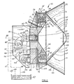
- the preferred embodiment of the invention is a radiant heater generally designated by reference numeral 10, which is illustrated in and will now be described with reference to FIGURES 1 through 5.
- the primary components of radiant heater 10 are, a housing 12, a combustion chamber 14, a heat exchange chamber 16, a heat exchanger 18, a radiator 20 and a reflector 22.
- Housing 12 is generally cylindrical in crosssection, having a central core portion 13, and an outer circumference portion 15, which are secured in relative position by a plurality of struts 17 which are welded to portions 13 and 15.
- Attached to housing 12 are front and rear mounting brackets 24 and 26.
- Rear mounting brackets 24 has apertures 28 which are adpated to receive a fixed shaft 30.
- the ends 32 of fixed shaft 30 are received in apertures 34 of supports 36, in order that housing 12 may be mounted in factory premises or on a platform 19 of a trailer 21 as illustrated in FIGURE 1.
- Front mounting bracket 26 is adapted to be connected to hydraulic mounts 23 on platform 19, in order that the central axis 38 of radiant heater 10 may be adjusted vertically. Radiant heater 10 is not capable of lateral adjustment, other than through relative positioning of platform 19 upon which heater 10 is mounted.
- Combustion chamber 14 is disposed within housing 12, and defined central axis 38.
- Combustion chamber 14 has an intake end 40 having an intake opening 42 thereat.
- a gas burner 44 Positioned at intake opening 42 is a gas burner 44.
- Combustion air is provided to burner 44 through fresh air inlet 46, which is connected by air duct 48 to end 50 of burner 44.
- Combustion chamber 14 has an exhaust end 52 having a discharge opening 54 thereat.
- Combustion chamber 14 defines a flow passage for products of combustion along central axis 38.
- Intake end 40 of combustion chamber 14 progressively increases in size about central axis 38 from intake opening 42 towards discharge opening 54.
- Exhaust end 52 of combustion chamber 14 progressively decreases in size from intake end 40 to discharge opening 54 of combustion chamber 14.
- Burner 44 has a fuel pump 45 which draws fuel from fuel tank 47 through filter 49 and fuel suction line 51.
- Burner 44 is a two stage burner and has a first stage nozzle 53 and a second stage nozzle 55.
- the flow of fuel from fuel pump 45 to nozzles 53 and 55 are controlled by solenoid valves 57, which open to permit the passage of fuel at 34 second intervals. Should the air fuel mixture fail to ignite, solenoid valves 57 remain closed in order to prevent an excess of fuel from being pumped into burner 44. Excess fuel is returned to fuel tank 47 through fuel return line 59.
- the presence of solenoid valves 57 and fuel return line 59 are safety features to prevent the possibility of explosions.
- Burner 44 can be adapted for operation on any of a number of fuels, such as propane, natural gas, diesel fuel, kerosene, and the like.
- Radiator 20 is in the form of a corrugated conical shell having a larger end 56 concentrically disposed about axis 38 and adjacent intake end 40 of combustion chamber 14, and a smaller end 58 concentrically disposed about axis 38. Radiator 20 defines exhaust end 52 of combustion chamber 14 and serves to radiate heat radially outwardly of exhaust end 52 of combustion chamber 14. Radiator 20 has a plurality of corrugations 61 disposed in planes 62 containing central axis 38. Corrugations 61 are open with the exception of an 18 inch (45.72 cm) portion remote from smaller end 58, which is enclosed forming fluid flow passages 60. Passages 60 have an inlet end opening 64 communicating with combustion chamber 14 and an outlet end 66 remote communicating with heat exchange chamber 16.
- Conical radiator 20 has an iregular exterior surface 72, which can be attributed to the presence of corrugations 61, which are present on both the interior and exterior surfaces. Corrugations 61 serve to provide a greater surface area for the radiation of heat.
- Reflector 22 surrounds radiator 20 for reflecting axially outwardly of housing 12 heat radiated by radiator 20. Radiator 20 is made out of materials which are known by the trade name "Ferrotherm 4816". Ferrotherm 4816 was originally developed for use in atomic reactors, and has a composition which includes 79.9% nickel and .29% titanium for resistance to temperature, and 1.2% aluminum for flexibility. The surface of reflector 22 is subjected to a treatment which is described by Krupp Industries of Germany as being "glo-heated”. The applicant has attempted to obtain further particulars of this treatment for the purpose of making a full and complete disclosure, and has been advised that the treatment is a trade secret of Krupp Industries.
- Heat exchange chamber 16 surrounds intake end 40 of combustion chamber 14.
- Heat exchange chamber 16 has two annular rings, a collector ring 76 and an exhaust ring 78.
- Collector ring 76 communicates with outlet end 66 of each of passages 60.
- Exhaust ring 78 has an opening 80 which is connected to exhaust duct 82. There are two openings 77, which permit communication of exhaust gases between collector ring 76 and exhaust ring 78.
- Exhaust ring 78 is smaller in size than collector ring 76 as the air has cooled down and contracted somewhat by the time it reaches exhaust ring 78.
- a heat exchanger 18 is disposed within heat exchange chamber 16.
- Heat exchanger 18 is comprised of two of pipes, 84 and 86, configured in coils.
- Pipe 84 is positioned in collector ring 76.
- Pipe 84 is connected at one end 85 to cold air intake duct 88 and at the opposite end 89 to hot air outlet duct 90.
- Pipe 84 is formed into nine coils 92 within collector ring 76.
- An air blower 94 is connected to cold air intake duct 88 at end 85 of pipe 84 to blow ambient air through pipe 84. As air circulates within coils 92 of pipe 84, the air becomes heated by the products of combustion in collector ring 76.
- End 89 of pipe 84 is adapted to be connected to the duct work of a hot air heating system (not shown).
- Pipe 86 is positioned in exhaust ring 78.
- Pipe 86 is connected at one end 95 to cold water intake duct 96 and at the opposite end 97 to hot water outlet duct 98.
- Cold water intake duct 96 is adapted to be connected to a water source (not shown).
- a manual control valve 100 is placed at end 95 of pipe 86 to control water flow.
- Pipe 86 is formed into three coils 102, within exhaust ring 78. As water circulates through coils 102 of pipe 86, the water becomes heated by the products of combustion within exhaust ring 78.
- End 97 of pipe 86 is adapted to be connected to a network or pipes forming a hot water heating system (not shown).
- burner 44 is connected to fuel tank 47, and air is drawn through fresh air inlet 46 via air duct 48 until the air/fuel mixture is ignited within combustion chamber 14.
- the products of combustion pass through intake opening 42 at intake end 40 of combustion chamber 14 and move along central axis 38 to discharge opening 54 at discharge end 52 of combustion chamber 14.
- At discharge end 52 the products of combustion pass through discharge opening 54 into inlet end 64 of passage 60.
- the movement of the products of combustion along passage 60 is retarded by baffle partitions 68 and a spiral baffle 70 within passages 60.
- baffle partitions 68 and a spiral baffle 70 within passages 60.
- Hot air outlet duct 90 serves a secondary function of preheating the air which enters through fresh air inlet 46 into burner 44. This is accomplished by placing air duct 48 and hot air outlet duct 90 in close proximity such that a partial heat exchange takes place. Preheating the air entering burner 44, assists in combustion, provided the air is not heated to too great an extent. Preheating the air to approximately 50 degrees celsius is viewed as acceptable. Due to the tendency of air to expand when heated, heating the air to too great an extend can create an undesirable back pressure within the system.
- Corrugations 61 serve to provide a larger surface area for the radiation of heat.
- Reflector 22 reflects outwardly the heat of radiator 20.
- radiant heater 10 has increased versatility and adaptability as radiant heat, hot water, or heated air can be supplied as the application demands. It will be apparent to one skilled in the art that radiant heater 10, can be adapted to provide steam heating, by circulating water within heat exchanger 18 until it becomes converted to steam.
- Radiator 20 is constructed to be able to withstand temperature approaching 1500 degrees centigrade. In controlled tests conducted by the Alberta Research Council, the radiant heat produced was between 1150 and 1250 degrees centigrade, and hot air output was 600 cubic feet per minute (0.283 m3/s) at a temperature of 680 degrees centigrade.
Landscapes
- Engineering & Computer Science (AREA)
- Chemical & Material Sciences (AREA)
- Combustion & Propulsion (AREA)
- Mechanical Engineering (AREA)
- General Engineering & Computer Science (AREA)
- Air-Conditioning For Vehicles (AREA)
- Electric Stoves And Ranges (AREA)
- Electric Ovens (AREA)
- Air Supply (AREA)
- Gas Burners (AREA)
- Central Heating Systems (AREA)
- Cookers (AREA)
Claims (7)
- Appareil de chauffage par rayonnement comportant un boîtier (12); une chambre de combustion(14) dans ce boîtier, cette chambre ayant un axe central (38) et présentant une extrémité d'admission (40) ayant une ouverture d'admission (42) et un extrémité d'échappement (52) ayant une ouverture d'échappement (54), cette chambre délimitant un passage pour l'écoulemnt des produits de combustion le long de l'axe central; des moyens de rayonnement entourant la chambre de combustion(14), ces moyens de rayonnement (20) délimitant ladite extrémité d'échappement (52) de la chambre de combustion (14) pour rayonner de la chaleur à l'extérieur de l'extrémité d'échappement de la chambre de combustion, ces moyens de rayonnement (20) comportant une série de passages d'écoulement de fluide (60) disposés dans des plans (62) contenant l'axe central (38) et des moyens réfléchissants (22) entourant les moyens de rayonnement (20) pour réfléchir axialement à l'extérieur du boîtier (12) la chaleur rayonnée par les moyens de rayonnement (20), caractérisé par une chambre d'échange thermique (16) entourant l'extrémité d'admission (40) de la chambre de combustion (14); un échangeur thermique (18) disposé à l'intérieur de cette chambre d'échange thermique (16); chacun des passages (60) comportant une extrémité d'entrée (64) communiquant avec la chambre de combustion (14) et une extrémité de sortie (66) débouchant dans la chambre d'échange thermique (16), les produits de combustion entrant ainsi dans les extrémités d'entrée (64) , s'y écoulant et pénétrant dans la chambre d'échange thermique (16), l'échangeur thermique (18) comprenant deux tuyaux (84,86) en serpentin, le premier tuyau (84) étant relié par une extrémité (85) à un conduit d'entrée d'air froid (88) et par son extrémité opposée (89) à un conduit de sortie d'air chaud (90) alors que le second tuyau (86) est relié par une extrémité (95) à un conduit d'arrivée d'eau froide (96) et par son extrémité opposée (97) à un conduit de sortie d'eau chaude (98).
- Appareil de chauffage par rayonnement selon la revendication 1, caractérisé en ce que l'extrémité d'admission (40) de la chambre de combustion (14) décroît progressivement de section autour de son axe central (38) de son ouverture d'admission (42) vers son ouverture de d'échappement (54).
- Appareil de chauffage par rayonnement selon la revendication 1 ou 2, caractérisé en ce que l'extrémité d'échappement (52) de la chambre de combustion (14) décroît progressivement de section de l'extrémité d'admission (40) de la chambre de combustion (14) vers son ouverture d'échappement (54).
- Appareil de chauffage par rayonnement selon l'une quelconque des revendications 1 à 3, caractérisé en ce que les moyens de rayonnement (20) ont la forme d'une coquille conique présentant une grande extrémité (56) disposée autour de l'axe (38) et adjacente à l'extrémité d'admission (40) de la chambre de combustion (14) et une petite extrémité (58) disposée concentriquement autour de l'axe (38) et délimitant l'ouverture d'échappement (54)
- Appareil de chauffage par rayonnement selon la revendication 4, caractérisé en ce que des moyens de retardement (68,70) sont disposés dans les passages (60) de sorte que l'écoulement des gaz d'échappement de l'extrémité d'entrée (64) à l'extrémité de sortie (66) peut être retardé pour retenir la chaleur à l'intérieur du radiateur.
- Appareil de chauffage par rayonnement selon la revendication 5, caractérisé en ce que les moyens de retardement comprennent une ou plusieurs cloisons (68) formant chicanes et disposées dans les passages (60).
- Appareil de chauffage selon larendication 5, caractérisé en ce qu'il comporte une chicane hélicoïdale (70) disposée dans les passages (60)
Priority Applications (1)
| Application Number | Priority Date | Filing Date | Title |
|---|---|---|---|
| AT88116924T ATE93040T1 (de) | 1987-10-13 | 1988-10-12 | Strahlungsheizung. |
Applications Claiming Priority (2)
| Application Number | Priority Date | Filing Date | Title |
|---|---|---|---|
| CA000549184A CA1267353A (fr) | 1987-10-13 | 1987-10-13 | Appareil chauffant par rayonnement |
| CA549184 | 1987-10-13 |
Publications (3)
| Publication Number | Publication Date |
|---|---|
| EP0312005A2 EP0312005A2 (fr) | 1989-04-19 |
| EP0312005A3 EP0312005A3 (en) | 1989-07-19 |
| EP0312005B1 true EP0312005B1 (fr) | 1993-08-11 |
Family
ID=4136636
Family Applications (1)
| Application Number | Title | Priority Date | Filing Date |
|---|---|---|---|
| EP88116924A Expired - Lifetime EP0312005B1 (fr) | 1987-10-13 | 1988-10-12 | Chauffage par radiation |
Country Status (5)
| Country | Link |
|---|---|
| EP (1) | EP0312005B1 (fr) |
| JP (1) | JPH01252808A (fr) |
| AT (1) | ATE93040T1 (fr) |
| CA (1) | CA1267353A (fr) |
| DE (1) | DE3883138T2 (fr) |
Families Citing this family (1)
| Publication number | Priority date | Publication date | Assignee | Title |
|---|---|---|---|---|
| US6629837B2 (en) * | 2000-02-10 | 2003-10-07 | Philip C. Carbone | Integrated premixed indirect radiant burner |
Family Cites Families (4)
| Publication number | Priority date | Publication date | Assignee | Title |
|---|---|---|---|---|
| FR2174789B1 (fr) * | 1972-03-06 | 1976-03-05 | Entr Indle Chaudronnerie Fr | |
| US3805763A (en) * | 1972-08-21 | 1974-04-23 | E Cowan | Flush-mountable, self-cooling gas-fired heater |
| US3763847A (en) * | 1972-09-07 | 1973-10-09 | Foster Miller Ass | Radiant heater |
| FR2267524A1 (en) * | 1974-04-12 | 1975-11-07 | Florarm | Bowl shaped overhead radiant heater - has refractory lined upper shell clamped onto stainless steel lower shell |
-
1987
- 1987-10-13 CA CA000549184A patent/CA1267353A/fr not_active Expired - Lifetime
-
1988
- 1988-10-12 AT AT88116924T patent/ATE93040T1/de not_active IP Right Cessation
- 1988-10-12 EP EP88116924A patent/EP0312005B1/fr not_active Expired - Lifetime
- 1988-10-12 DE DE88116924T patent/DE3883138T2/de not_active Expired - Fee Related
- 1988-10-13 JP JP63258311A patent/JPH01252808A/ja active Pending
Also Published As
| Publication number | Publication date |
|---|---|
| CA1267353A (fr) | 1990-04-03 |
| EP0312005A3 (en) | 1989-07-19 |
| JPH01252808A (ja) | 1989-10-09 |
| DE3883138D1 (de) | 1993-09-16 |
| EP0312005A2 (fr) | 1989-04-19 |
| DE3883138T2 (de) | 1994-04-14 |
| ATE93040T1 (de) | 1993-08-15 |
Similar Documents
| Publication | Publication Date | Title |
|---|---|---|
| US5022352A (en) | Burner for forced draft controlled mixture heating system using a closed combustion chamber | |
| CA2130964C (fr) | Chauffe-eau muni d'un bruleur en ceramique a faible degagement d'oxydes d'azote | |
| US5791298A (en) | Water heater with low emission gas burner | |
| US3267985A (en) | Pulse combustion apparatus | |
| CA2123356C (fr) | Chauffe-eau a utilisation sur demande ultra-efficace | |
| EP0180417A2 (fr) | Dispositif de combustion pulsatoire | |
| GB2174790A (en) | Heat exchanger | |
| US4056143A (en) | Heat exchange apparatus | |
| CA2093169C (fr) | Chauffe-eau a tube u multiple a flamme orientee vers le bas | |
| US6725811B1 (en) | Water heater with low NOx fiber matrix burner | |
| MXPA96003116A (es) | Dispositivo para reduccion de nox para quemador decombustible de encendido con estructura para soporte de colocacion integral. | |
| US20100313827A1 (en) | High-Efficiency Gas-Fired Forced-Draft Condensing Hot Water Boiler | |
| US4780076A (en) | Power burner | |
| US4926798A (en) | Process for pulse combustion | |
| US5033450A (en) | Radiant heater | |
| EP0312005B1 (fr) | Chauffage par radiation | |
| US4823768A (en) | Radiant heater | |
| GB2160967A (en) | Gas-fired space heating unit | |
| CA1119507A (fr) | Appareil de chauffage a combustion pulsee | |
| US4773390A (en) | Demand hot water system | |
| RU2039326C1 (ru) | Агрегатный теплообменник для установки кондиционирования воздуха | |
| US11906159B2 (en) | Frustoconical combustion chamber for a fluid heating device and methods for making the same | |
| US4905661A (en) | Heat exchanger | |
| US4805590A (en) | Gas space heating unit | |
| CA2003869C (fr) | Systeme de combustion a pulsations et procede connexe |
Legal Events
| Date | Code | Title | Description |
|---|---|---|---|
| PUAI | Public reference made under article 153(3) epc to a published international application that has entered the european phase |
Free format text: ORIGINAL CODE: 0009012 |
|
| AK | Designated contracting states |
Kind code of ref document: A2 Designated state(s): AT BE CH DE ES FR GB IT LI NL SE |
|
| PUAL | Search report despatched |
Free format text: ORIGINAL CODE: 0009013 |
|
| AK | Designated contracting states |
Kind code of ref document: A3 Designated state(s): AT BE CH DE ES FR GB IT LI NL SE |
|
| 17P | Request for examination filed |
Effective date: 19900118 |
|
| 17Q | First examination report despatched |
Effective date: 19901123 |
|
| GRAA | (expected) grant |
Free format text: ORIGINAL CODE: 0009210 |
|
| AK | Designated contracting states |
Kind code of ref document: B1 Designated state(s): AT BE CH DE ES FR GB IT LI NL SE |
|
| PG25 | Lapsed in a contracting state [announced via postgrant information from national office to epo] |
Ref country code: IT Free format text: LAPSE BECAUSE OF FAILURE TO SUBMIT A TRANSLATION OF THE DESCRIPTION OR TO PAY THE FEE WITHIN THE PRE;WARNING: LAPSES OF ITALIAN PATENTS WITH EFFECTIVE DATE BEFORE 2007 MAY HAVE OCCURRED AT ANY TIME BEFORE 2007. THE CORRECT EFFECTIVE DATE MAY BE DIFFERENT FROM THE ONE RECORDED.SCRIBED TIME-LIMIT Effective date: 19930811 Ref country code: FR Effective date: 19930811 Ref country code: ES Free format text: THE PATENT HAS BEEN ANNULLED BY A DECISION OF A NATIONAL AUTHORITY Effective date: 19930811 Ref country code: CH Effective date: 19930811 Ref country code: BE Effective date: 19930811 Ref country code: SE Effective date: 19930811 Ref country code: LI Effective date: 19930811 Ref country code: NL Effective date: 19930811 |
|
| REF | Corresponds to: |
Ref document number: 93040 Country of ref document: AT Date of ref document: 19930815 Kind code of ref document: T |
|
| REF | Corresponds to: |
Ref document number: 3883138 Country of ref document: DE Date of ref document: 19930916 |
|
| PG25 | Lapsed in a contracting state [announced via postgrant information from national office to epo] |
Ref country code: GB Effective date: 19931111 |
|
| REG | Reference to a national code |
Ref country code: CH Ref legal event code: PL |
|
| EN | Fr: translation not filed | ||
| NLV1 | Nl: lapsed or annulled due to failure to fulfill the requirements of art. 29p and 29m of the patents act | ||
| PLBE | No opposition filed within time limit |
Free format text: ORIGINAL CODE: 0009261 |
|
| STAA | Information on the status of an ep patent application or granted ep patent |
Free format text: STATUS: NO OPPOSITION FILED WITHIN TIME LIMIT |
|
| GBPC | Gb: european patent ceased through non-payment of renewal fee |
Effective date: 19931111 |
|
| 26N | No opposition filed | ||
| PGFP | Annual fee paid to national office [announced via postgrant information from national office to epo] |
Ref country code: DE Payment date: 19941129 Year of fee payment: 7 |
|
| PGFP | Annual fee paid to national office [announced via postgrant information from national office to epo] |
Ref country code: AT Payment date: 19950309 Year of fee payment: 7 |
|
| PG25 | Lapsed in a contracting state [announced via postgrant information from national office to epo] |
Ref country code: AT Effective date: 19951012 |
|
| PG25 | Lapsed in a contracting state [announced via postgrant information from national office to epo] |
Ref country code: DE Effective date: 19960702 |