EP0312029B1 - Heizgerät für eine Spritzgiessmaschine - Google Patents
Heizgerät für eine Spritzgiessmaschine Download PDFInfo
- Publication number
- EP0312029B1 EP0312029B1 EP88116959A EP88116959A EP0312029B1 EP 0312029 B1 EP0312029 B1 EP 0312029B1 EP 88116959 A EP88116959 A EP 88116959A EP 88116959 A EP88116959 A EP 88116959A EP 0312029 B1 EP0312029 B1 EP 0312029B1
- Authority
- EP
- European Patent Office
- Prior art keywords
- heater
- nozzle
- electrically conductive
- molding machine
- injection molding
- Prior art date
- Legal status (The legal status is an assumption and is not a legal conclusion. Google has not performed a legal analysis and makes no representation as to the accuracy of the status listed.)
- Expired - Lifetime
Links
- 238000001746 injection moulding Methods 0.000 title claims abstract description 16
- 239000000919 ceramic Substances 0.000 claims abstract description 33
- 238000002347 injection Methods 0.000 claims abstract description 20
- 239000007924 injection Substances 0.000 claims abstract description 20
- 238000010438 heat treatment Methods 0.000 claims abstract description 14
- 230000002093 peripheral effect Effects 0.000 claims abstract description 12
- 238000010285 flame spraying Methods 0.000 claims abstract description 9
- 238000000465 moulding Methods 0.000 claims description 5
- 229910010293 ceramic material Inorganic materials 0.000 description 4
- 239000004020 conductor Substances 0.000 description 3
- 239000011347 resin Substances 0.000 description 3
- 229920005989 resin Polymers 0.000 description 3
- 230000007774 longterm Effects 0.000 description 2
- 230000003190 augmentative effect Effects 0.000 description 1
- 230000005540 biological transmission Effects 0.000 description 1
- 230000006866 deterioration Effects 0.000 description 1
- 230000008018 melting Effects 0.000 description 1
- 238000002844 melting Methods 0.000 description 1
- 239000012768 molten material Substances 0.000 description 1
- 230000005855 radiation Effects 0.000 description 1
- 238000005507 spraying Methods 0.000 description 1
- 238000004804 winding Methods 0.000 description 1
Images
Classifications
-
- B—PERFORMING OPERATIONS; TRANSPORTING
- B29—WORKING OF PLASTICS; WORKING OF SUBSTANCES IN A PLASTIC STATE IN GENERAL
- B29C—SHAPING OR JOINING OF PLASTICS; SHAPING OF MATERIAL IN A PLASTIC STATE, NOT OTHERWISE PROVIDED FOR; AFTER-TREATMENT OF THE SHAPED PRODUCTS, e.g. REPAIRING
- B29C45/00—Injection moulding, i.e. forcing the required volume of moulding material through a nozzle into a closed mould; Apparatus therefor
- B29C45/17—Component parts, details or accessories; Auxiliary operations
- B29C45/72—Heating or cooling
- B29C45/74—Heating or cooling of the injection unit
-
- B—PERFORMING OPERATIONS; TRANSPORTING
- B29—WORKING OF PLASTICS; WORKING OF SUBSTANCES IN A PLASTIC STATE IN GENERAL
- B29C—SHAPING OR JOINING OF PLASTICS; SHAPING OF MATERIAL IN A PLASTIC STATE, NOT OTHERWISE PROVIDED FOR; AFTER-TREATMENT OF THE SHAPED PRODUCTS, e.g. REPAIRING
- B29C45/00—Injection moulding, i.e. forcing the required volume of moulding material through a nozzle into a closed mould; Apparatus therefor
- B29C45/17—Component parts, details or accessories; Auxiliary operations
- B29C45/26—Moulds
- B29C45/27—Sprue channels ; Runner channels or runner nozzles
- B29C45/2737—Heating or cooling means therefor
-
- H—ELECTRICITY
- H05—ELECTRIC TECHNIQUES NOT OTHERWISE PROVIDED FOR
- H05B—ELECTRIC HEATING; ELECTRIC LIGHT SOURCES NOT OTHERWISE PROVIDED FOR; CIRCUIT ARRANGEMENTS FOR ELECTRIC LIGHT SOURCES, IN GENERAL
- H05B3/00—Ohmic-resistance heating
- H05B3/40—Heating elements having the shape of rods or tubes
- H05B3/42—Heating elements having the shape of rods or tubes non-flexible
-
- B—PERFORMING OPERATIONS; TRANSPORTING
- B29—WORKING OF PLASTICS; WORKING OF SUBSTANCES IN A PLASTIC STATE IN GENERAL
- B29C—SHAPING OR JOINING OF PLASTICS; SHAPING OF MATERIAL IN A PLASTIC STATE, NOT OTHERWISE PROVIDED FOR; AFTER-TREATMENT OF THE SHAPED PRODUCTS, e.g. REPAIRING
- B29C45/00—Injection moulding, i.e. forcing the required volume of moulding material through a nozzle into a closed mould; Apparatus therefor
- B29C45/17—Component parts, details or accessories; Auxiliary operations
- B29C45/26—Moulds
- B29C45/27—Sprue channels ; Runner channels or runner nozzles
- B29C45/2737—Heating or cooling means therefor
- B29C2045/2743—Electrical heating element constructions
- B29C2045/2745—Film-like electrical heaters
-
- B—PERFORMING OPERATIONS; TRANSPORTING
- B29—WORKING OF PLASTICS; WORKING OF SUBSTANCES IN A PLASTIC STATE IN GENERAL
- B29C—SHAPING OR JOINING OF PLASTICS; SHAPING OF MATERIAL IN A PLASTIC STATE, NOT OTHERWISE PROVIDED FOR; AFTER-TREATMENT OF THE SHAPED PRODUCTS, e.g. REPAIRING
- B29C45/00—Injection moulding, i.e. forcing the required volume of moulding material through a nozzle into a closed mould; Apparatus therefor
- B29C45/17—Component parts, details or accessories; Auxiliary operations
- B29C45/26—Moulds
- B29C45/27—Sprue channels ; Runner channels or runner nozzles
- B29C45/2737—Heating or cooling means therefor
- B29C2045/2743—Electrical heating element constructions
- B29C2045/2748—Insulating layers covering the electrical heating element
-
- B—PERFORMING OPERATIONS; TRANSPORTING
- B29—WORKING OF PLASTICS; WORKING OF SUBSTANCES IN A PLASTIC STATE IN GENERAL
- B29C—SHAPING OR JOINING OF PLASTICS; SHAPING OF MATERIAL IN A PLASTIC STATE, NOT OTHERWISE PROVIDED FOR; AFTER-TREATMENT OF THE SHAPED PRODUCTS, e.g. REPAIRING
- B29C45/00—Injection moulding, i.e. forcing the required volume of moulding material through a nozzle into a closed mould; Apparatus therefor
- B29C45/17—Component parts, details or accessories; Auxiliary operations
- B29C45/26—Moulds
- B29C45/27—Sprue channels ; Runner channels or runner nozzles
- B29C45/2737—Heating or cooling means therefor
- B29C2045/2754—Plurality of independent heating or cooling means, e.g. independently controlling the heating of several zones of the nozzle
Definitions
- This invention relates to a heater for heating the section to be heated, such as an injection nozzle or a plasticizing cylinder in an injection molding machine.
- the outer diameter of the nozzle directly affects the strength of the mold or the effective area of the cavity for injection molding since an inserting hole of a size that fits the outer nozzle diameter must be provided in the mold.
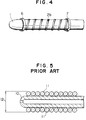
- the outer diameter 12 of a nozzle 10 is kept as small as possible by winding an extremely thin coil heater 11 around the outer peripheral surface of the nozzle 10, thus bringing the coil into close contact with the nozzle, making use of the elasticity of the coil.
- the adherence of the coil heater 11 to the nozzle 10 is subject to becoming loose or being displaced when used for long time, making it impossible to retain the initial conditions for a long period of time.
- US-A-4 583 284 discloses a heater for an injection molding machine for molding by injecting molten plastic into a mold, said heater comprising a helical electrically conductive film on the outer peripheral surface of the molding machine sections to be heated such as the heating cylinder and the injection nozzle.
- DE-A-19 24 202 discloses a sprayed conductive coat in connection with an electrical heating device.
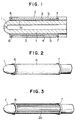
- a film heater 2 consisting of a ceramic material is formed by flame spraying on the outer peripheral surface of a nozzle 1 for injecting molten plastic into a mold.
- This film heater 2 is composed of an insulating film 3, the innermost layer, formed by flame spraying on the outer peripheral surface 1a of the nozzle 1, an electrically conductive ceramic film 4, the middle layer, formed by flame spraying on the insulating ceramic film 3, and an insulating ceramic film 5, the outermost layer, formed by flame spraying on the electrically conductive ceramic film 4.
- Electrodes 6 and 7 for feeding power are provided at both ends of the electrically conductive ceramic film 4.
- the nozzle 1 and the electrically conductive film 4 are insulated from each other by film spraying the insulating ceramic film 3 on the outer peripheral surface of the nozzle 1.
- Figs. 3 shows an embodiment of this invention. Since this embodiment and the heater of Fig. 4 are basically identical with that shown in Figs. 1 and 2, only the differences between them will be explained.
- the electrically conductive ceramic film is in the form of a plurality of longitudinal stripes 2a connecting the electrodes 6 and 7.
- the electrically conductive ceramic film is in the form of a multitude of helical strips 2b. While in Figs. 3 and 4 the electrically conductive ceramic films are shown as films directly formed on the outer peripheral surface of the nozzle 1, it goes without saying that the electrically conductive ceramic films may be formed between the insulating ceramic films, as in the embodiment shown in Figs. 1 and 2.
- the heater in accordance with this invention is formed by flame spraying an electrically conductive ceramic material, it is formed substantially in one body with the section to be heated such as the heating cylinder or the nozzle, so that its adhering force is not weakened even after long-term use. Since the thickness of the ceramic film heater 2 is 0.5 mm or so, it results in a nozzle heater with a small outer nozzle diameter. Furthermore, a ceramic heater of this type is formed by flame spraying, so that it does not burn out.
- the whole surface of the section to be heated is coated with an electrically conductive ceramic
- uneven heating due to differences in electrical resistance can occur unless the thickness of the film is uniform over the surface.
- This can be avoided by forming the electrically conductive ceramic film as substantially linear conductors in the form of longitudinal stripes or helical strips. Uneven heating can then be mitigated even when there is some variation in the film thickness.
- the heater for an injection molding machine of this invention is formed as a film heater by flame spraying a ceramic material on the outer peripheral surface of the nozzle, it is not subject to deterioration in adhering force due to the long-term use thereof, which has been a problem in conventional coil heaters. It can consequently retain the initial conditions for a long period of time. Furthermore, since the thickness of the film heater can be limited to 0.5 mm or so, it can give a nozzle heater with a small outer nozzle diameter. At the same time, any accident due to burning out of a heater can be avoided.
- the heater of this invention can consequently lead to an injection molding machine nozzle of high practical value.
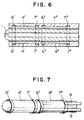
- Figs. 6 and 7 show an embodiment in which two separate electrically conductive ceramic films 4' and 4'' are provided in the longitudinally front and rear section of the outer peripheral surface of the nozzle 1.
- the embodiment includes electrodes 6' and 7' at both ends of the electrically conductive ceramic film 4' and electrodes 6'' and 7'' at both ends of the electrically conductive ceramic film 4''.
- the electrodes 6'' and 7'' are respectively connected to the power source through heat-proof converted ribbon conductors 8 and 9 extending longitudinally rearwards.
- the electrodes 6' and 7' are also connected to the power source through heat-proof covered ribbon conductors extending longitudinally rearwards on the other side of the drawing. This embodiment enables the entire injection nozzle to be heated as evenly as possible.
- the front end of the injection nozzle is in contact with a mold which is set at a temperature which is far lower than the melting point of the molten material such as plastic, its temperature is normally lower than the set temperature value of the injection nozzle by tens of degrees C.
- the rear section of the injection nozzle heat transmission from the heating cylinder.
- the heat radiation from the injection nozzle is low, so that the injection nozzle tends to be overheated.
- the entire nozzle can be set to a uniform optimum temperature by setting the nozzle front end to a high temperature and the nozzle rear section to a normal temperature.
- the above described problem which is involved when only one heater is provided can thus be overcome. While in the embodiment shown in Figs. 6 and 7 the entire peripheral surface of the injection nozzle is coated with an electrically conductive ceramic material, the two conductive ceramic films in the front and rear sections of the nozzle may be in the form of longitudinal stripes or helical strips as in Figs. 3 and 4.
Landscapes
- Engineering & Computer Science (AREA)
- Manufacturing & Machinery (AREA)
- Mechanical Engineering (AREA)
- Injection Moulding Of Plastics Or The Like (AREA)
- Heating, Cooling, Or Curing Plastics Or The Like In General (AREA)
Claims (3)
- Heizgerät (2) für eine Spritzgießmaschine zum Spritz-Formen durch Einspritzen von Kunststoffschmelze in eine Spritz-Form, wobei das Heizgerät einen elektrisch leitenden Film (4) auf der Außenumfangsfläche (1a) der zu beheizenden Gießmaschinenabschnitte, wie Heizzylinder und Spritzdüse (1), umfaßt,
dadurch gekennzeichnet, daß
der elektrisch leitende Film (4) aus einem durch Flammsprühen ausgebildeten Keramikmaterial geformt ist und der elektrisch leitende Keramikfilm in Form längsverlaufender Streifen (2a) ausgebildet ist. - Heizgerät für eine Spritzgießmaschine nach Anspruch 1, wobei die Temperatur der vorderen und hinteren Abschnitte oder Bereiche der Spritzdüse (1) mittels zweier getrennter Keramikfilme (4', 4''), die in den vorderen und hinteren Abschnitten oder Bereichen der Spritzdüse (1) geformt sind, getrennt geregelt wird.
- Heizgerät für eine Spritzgießmaschine nach Anspruch 1 oder 2, wobei der elektrisch leitende Keramikfilm (4) zwischen isolierenden Keramikfilmen (3, 5) geformt ist.
Priority Applications (1)
| Application Number | Priority Date | Filing Date | Title |
|---|---|---|---|
| AT8888116959T ATE105455T1 (de) | 1987-10-12 | 1988-10-12 | Heizgeraet fuer eine spritzgiessmaschine. |
Applications Claiming Priority (2)
| Application Number | Priority Date | Filing Date | Title |
|---|---|---|---|
| JP62254682A JP2561489B2 (ja) | 1987-10-12 | 1987-10-12 | 射出成形機用ヒータ |
| JP254682/87 | 1987-10-12 |
Publications (2)
| Publication Number | Publication Date |
|---|---|
| EP0312029A1 EP0312029A1 (de) | 1989-04-19 |
| EP0312029B1 true EP0312029B1 (de) | 1994-05-04 |
Family
ID=17268401
Family Applications (1)
| Application Number | Title | Priority Date | Filing Date |
|---|---|---|---|
| EP88116959A Expired - Lifetime EP0312029B1 (de) | 1987-10-12 | 1988-10-12 | Heizgerät für eine Spritzgiessmaschine |
Country Status (5)
| Country | Link |
|---|---|
| EP (1) | EP0312029B1 (de) |
| JP (1) | JP2561489B2 (de) |
| KR (1) | KR970002299B1 (de) |
| AT (1) | ATE105455T1 (de) |
| DE (1) | DE3889410T2 (de) |
Cited By (6)
| Publication number | Priority date | Publication date | Assignee | Title |
|---|---|---|---|---|
| US6305923B1 (en) | 1998-06-12 | 2001-10-23 | Husky Injection Molding Systems Ltd. | Molding system using film heaters and/or sensors |
| US7044191B2 (en) | 2000-05-24 | 2006-05-16 | Mold-Masters Limited | Mold material processing device, method and apparatus for producing same |
| US7241131B1 (en) | 2000-06-19 | 2007-07-10 | Husky Injection Molding Systems Ltd. | Thick film heater apparatus |
| WO2007123428A1 (en) * | 2006-04-24 | 2007-11-01 | Volastic Co. Limited | Injection moulding nozzle and tip therefor |
| CN1922925B (zh) * | 2004-01-06 | 2012-10-10 | 沃特洛电气制造公司 | 热传递相适配的层状加热器系统 |
| DE10362064B4 (de) * | 2003-08-16 | 2014-07-24 | gwk Gesellschaft Wärme Kältetechnik mbH | Beheizbares Werkzeug |
Families Citing this family (10)
| Publication number | Priority date | Publication date | Assignee | Title |
|---|---|---|---|---|
| US5973296A (en) * | 1998-10-20 | 1999-10-26 | Watlow Electric Manufacturing Company | Thick film heater for injection mold runner nozzle |
| CA2311829A1 (en) | 2000-06-16 | 2001-12-16 | Jonathon Fischer | Thermally balanced hot runner nozzle |
| KR100683915B1 (ko) * | 2004-12-13 | 2007-02-15 | 김관표 | 사출성형기용 노즐 및 제조방법 |
| DE102005014566B4 (de) * | 2005-03-17 | 2010-07-22 | Kraussmaffei Technologies Gmbh | Thermoverschlussdüse und Verfahren zum Beheizen einer solchen |
| US7280750B2 (en) | 2005-10-17 | 2007-10-09 | Watlow Electric Manufacturing Company | Hot runner nozzle heater and methods of manufacture thereof |
| JP2009216590A (ja) * | 2008-03-11 | 2009-09-24 | Makome Kenkyusho:Kk | 絶対値型磁気スケール装置 |
| DE102009050288A1 (de) * | 2009-10-15 | 2011-04-21 | Beru Ag | Elektrisch beheizbare Sprühdüse |
| WO2014150632A1 (en) * | 2013-03-18 | 2014-09-25 | Husky Injection Molding Systems Ltd. | Melt control in an injection molding system |
| CN109366900B (zh) * | 2018-12-13 | 2021-05-25 | 盐城市沿海新能源汽车科技有限公司 | 一种热流道热嘴保护装置 |
| DE102021129015A1 (de) * | 2021-11-08 | 2023-05-11 | Sebastian Pütter | Temperiervorrichtung für eine Plastifizierschnecke und/oder einen Plastifizierzylinder einer Plastifiziereinheit |
Family Cites Families (4)
| Publication number | Priority date | Publication date | Assignee | Title |
|---|---|---|---|---|
| US2683673A (en) * | 1952-03-10 | 1954-07-13 | Electrofilm Corp | Film-type heating element |
| AT205619B (de) * | 1957-02-05 | 1959-10-10 | Kanthal Ab | Elektrisches Widerstandselement |
| DE1924202A1 (de) * | 1969-05-12 | 1970-11-19 | Annawerk Keramische Betr E Gmb | Flaechenfoermige,elektrische Heizvorrichtung |
| CA1230458A (en) * | 1984-07-13 | 1987-12-22 | Gellert, Jobst Ulrich | Injection molding heated nozzle with brazed in heating element and method of manufacture |
-
1987
- 1987-10-12 JP JP62254682A patent/JP2561489B2/ja not_active Expired - Lifetime
-
1988
- 1988-10-11 KR KR1019880013237A patent/KR970002299B1/ko not_active Expired - Fee Related
- 1988-10-12 DE DE3889410T patent/DE3889410T2/de not_active Expired - Fee Related
- 1988-10-12 AT AT8888116959T patent/ATE105455T1/de not_active IP Right Cessation
- 1988-10-12 EP EP88116959A patent/EP0312029B1/de not_active Expired - Lifetime
Cited By (11)
| Publication number | Priority date | Publication date | Assignee | Title |
|---|---|---|---|---|
| US6305923B1 (en) | 1998-06-12 | 2001-10-23 | Husky Injection Molding Systems Ltd. | Molding system using film heaters and/or sensors |
| US6341954B1 (en) | 1998-06-12 | 2002-01-29 | Husky Injection Molding Systems Ltd. | Molding system using film heaters and/or sensors |
| US6575729B2 (en) | 1998-06-12 | 2003-06-10 | Husky Injection Molding Systems Ltd. | Molding system with integrated film heaters and sensors |
| US6764297B2 (en) | 1998-06-12 | 2004-07-20 | Husky Injection Molding Systems Ltd. | Molding system with integrated film heaters and sensors |
| US7029260B2 (en) | 1998-06-12 | 2006-04-18 | Husky Injection Molding Systems Ltd. | Molding apparatus having a film heater |
| US7071449B2 (en) | 1998-06-12 | 2006-07-04 | Husky Injection Molding Systems Ltd. | Molding system with integrated film heaters and sensors |
| US7044191B2 (en) | 2000-05-24 | 2006-05-16 | Mold-Masters Limited | Mold material processing device, method and apparatus for producing same |
| US7241131B1 (en) | 2000-06-19 | 2007-07-10 | Husky Injection Molding Systems Ltd. | Thick film heater apparatus |
| DE10362064B4 (de) * | 2003-08-16 | 2014-07-24 | gwk Gesellschaft Wärme Kältetechnik mbH | Beheizbares Werkzeug |
| CN1922925B (zh) * | 2004-01-06 | 2012-10-10 | 沃特洛电气制造公司 | 热传递相适配的层状加热器系统 |
| WO2007123428A1 (en) * | 2006-04-24 | 2007-11-01 | Volastic Co. Limited | Injection moulding nozzle and tip therefor |
Also Published As
| Publication number | Publication date |
|---|---|
| DE3889410T2 (de) | 1994-10-20 |
| DE3889410D1 (de) | 1994-06-09 |
| EP0312029A1 (de) | 1989-04-19 |
| JP2561489B2 (ja) | 1996-12-11 |
| KR970002299B1 (ko) | 1997-02-27 |
| JPH0197619A (ja) | 1989-04-17 |
| ATE105455T1 (de) | 1994-05-15 |
| KR890006366A (ko) | 1989-06-13 |
Similar Documents
| Publication | Publication Date | Title |
|---|---|---|
| EP0312029B1 (de) | Heizgerät für eine Spritzgiessmaschine | |
| US5973296A (en) | Thick film heater for injection mold runner nozzle | |
| US4875845A (en) | Injection nozzle for an injection molding machine | |
| US4530521A (en) | Electrically weldable socket for joining pipe members | |
| JPH0325336B2 (de) | ||
| JP3293594B2 (ja) | 光ファイバ融着接続部の保護部材加熱装置及び加熱方法 | |
| US4348584A (en) | Flexible heating elements and processes for the production thereof | |
| MXPA02012618A (es) | Boquilla de canal de colado en caliente termicamente equilibrada. | |
| JP2724623B2 (ja) | コネクタ成端装置および方法 | |
| US20190299311A1 (en) | High Power Dual Sensor Cartridge | |
| US6142207A (en) | Hot melt glue applicator and glue stick for use therein | |
| US4010351A (en) | Cartridge heater with improved thermocouple | |
| JPH0559559B2 (de) | ||
| CA2059960A1 (en) | Injection molding probe with coaxial thermocouple tube and heating ele ment | |
| BR112017023247B1 (pt) | Método para união de membros primário e secundário | |
| EP0902106A1 (de) | Ofen für eine Vorrichtung zum Ziehen optischer Fasern aus Kunststoff | |
| JPS61141959A (ja) | 熱溶融形接着剤施工ガン | |
| JPH10272653A (ja) | 射出成形機の射出ノズル | |
| DE102007010395A1 (de) | Verfahren zur Herstellung einer elektrischen Heizung und/oder eines Temperaturfühlers für Heißkanalsysteme | |
| CN114246372A (zh) | 加热器组件及气溶胶形成装置 | |
| JPH0755526B2 (ja) | 合成樹脂成形機の加熱装置 | |
| CN85109514A (zh) | 有硬钎焊接的加热元件的注射成型加热喷嘴及其制造方法 | |
| JP4039475B2 (ja) | ホットランナノズル | |
| CA2013950A1 (en) | Integrally heated torpedo | |
| JPS63102114A (ja) | 平形ケ−ブルの製造方法 |
Legal Events
| Date | Code | Title | Description |
|---|---|---|---|
| PUAI | Public reference made under article 153(3) epc to a published international application that has entered the european phase |
Free format text: ORIGINAL CODE: 0009012 |
|
| AK | Designated contracting states |
Kind code of ref document: A1 Designated state(s): AT CH DE FR GB LI |
|
| 17P | Request for examination filed |
Effective date: 19890824 |
|
| 17Q | First examination report despatched |
Effective date: 19920203 |
|
| GRAA | (expected) grant |
Free format text: ORIGINAL CODE: 0009210 |
|
| AK | Designated contracting states |
Kind code of ref document: B1 Designated state(s): AT CH DE FR GB LI |
|
| REF | Corresponds to: |
Ref document number: 105455 Country of ref document: AT Date of ref document: 19940515 Kind code of ref document: T |
|
| REF | Corresponds to: |
Ref document number: 3889410 Country of ref document: DE Date of ref document: 19940609 |
|
| ET | Fr: translation filed | ||
| PLBE | No opposition filed within time limit |
Free format text: ORIGINAL CODE: 0009261 |
|
| STAA | Information on the status of an ep patent application or granted ep patent |
Free format text: STATUS: NO OPPOSITION FILED WITHIN TIME LIMIT |
|
| 26N | No opposition filed | ||
| REG | Reference to a national code |
Ref country code: GB Ref legal event code: IF02 |
|
| PGFP | Annual fee paid to national office [announced via postgrant information from national office to epo] |
Ref country code: FR Payment date: 20021008 Year of fee payment: 15 |
|
| PGFP | Annual fee paid to national office [announced via postgrant information from national office to epo] |
Ref country code: GB Payment date: 20021009 Year of fee payment: 15 |
|
| PGFP | Annual fee paid to national office [announced via postgrant information from national office to epo] |
Ref country code: AT Payment date: 20021011 Year of fee payment: 15 |
|
| PGFP | Annual fee paid to national office [announced via postgrant information from national office to epo] |
Ref country code: CH Payment date: 20021016 Year of fee payment: 15 |
|
| PGFP | Annual fee paid to national office [announced via postgrant information from national office to epo] |
Ref country code: DE Payment date: 20021017 Year of fee payment: 15 |
|
| PG25 | Lapsed in a contracting state [announced via postgrant information from national office to epo] |
Ref country code: GB Free format text: LAPSE BECAUSE OF NON-PAYMENT OF DUE FEES Effective date: 20031012 Ref country code: AT Free format text: LAPSE BECAUSE OF NON-PAYMENT OF DUE FEES Effective date: 20031012 |
|
| PG25 | Lapsed in a contracting state [announced via postgrant information from national office to epo] |
Ref country code: LI Free format text: LAPSE BECAUSE OF NON-PAYMENT OF DUE FEES Effective date: 20031031 Ref country code: CH Free format text: LAPSE BECAUSE OF NON-PAYMENT OF DUE FEES Effective date: 20031031 |
|
| PG25 | Lapsed in a contracting state [announced via postgrant information from national office to epo] |
Ref country code: DE Free format text: LAPSE BECAUSE OF NON-PAYMENT OF DUE FEES Effective date: 20040501 |
|
| GBPC | Gb: european patent ceased through non-payment of renewal fee |
Effective date: 20031012 |
|
| REG | Reference to a national code |
Ref country code: CH Ref legal event code: PL |
|
| PG25 | Lapsed in a contracting state [announced via postgrant information from national office to epo] |
Ref country code: FR Free format text: LAPSE BECAUSE OF NON-PAYMENT OF DUE FEES Effective date: 20040630 |
|
| REG | Reference to a national code |
Ref country code: FR Ref legal event code: ST |