EP0312080A1 - Tragbare, automatische Vorrichtung zum Anreichern von Wasser mit Kohlensäure ohne elektrische Bauteile - Google Patents
Tragbare, automatische Vorrichtung zum Anreichern von Wasser mit Kohlensäure ohne elektrische Bauteile Download PDFInfo
- Publication number
- EP0312080A1 EP0312080A1 EP88117098A EP88117098A EP0312080A1 EP 0312080 A1 EP0312080 A1 EP 0312080A1 EP 88117098 A EP88117098 A EP 88117098A EP 88117098 A EP88117098 A EP 88117098A EP 0312080 A1 EP0312080 A1 EP 0312080A1
- Authority
- EP
- European Patent Office
- Prior art keywords
- carbonator
- water
- pressure
- gas
- chamber
- Prior art date
- Legal status (The legal status is an assumption and is not a legal conclusion. Google has not performed a legal analysis and makes no representation as to the accuracy of the status listed.)
- Granted
Links
Images


Classifications
-
- B—PERFORMING OPERATIONS; TRANSPORTING
- B67—OPENING, CLOSING OR CLEANING BOTTLES, JARS OR SIMILAR CONTAINERS; LIQUID HANDLING
- B67D—DISPENSING, DELIVERING OR TRANSFERRING LIQUIDS, NOT OTHERWISE PROVIDED FOR
- B67D1/00—Apparatus or devices for dispensing beverages on draught
- B67D1/04—Apparatus utilising compressed air or other gas acting directly or indirectly on beverages in storage containers
- B67D1/0412—Apparatus utilising compressed air or other gas acting directly or indirectly on beverages in storage containers the whole dispensing unit being fixed to the container
- B67D1/0443—Apparatus utilising compressed air or other gas acting directly or indirectly on beverages in storage containers the whole dispensing unit being fixed to the container comprising a gas generator
-
- B—PERFORMING OPERATIONS; TRANSPORTING
- B01—PHYSICAL OR CHEMICAL PROCESSES OR APPARATUS IN GENERAL
- B01F—MIXING, e.g. DISSOLVING, EMULSIFYING OR DISPERSING
- B01F23/00—Mixing according to the phases to be mixed, e.g. dispersing or emulsifying
- B01F23/20—Mixing gases with liquids
- B01F23/23—Mixing gases with liquids by introducing gases into liquid media, e.g. for producing aerated liquids
- B01F23/236—Mixing gases with liquids by introducing gases into liquid media, e.g. for producing aerated liquids specially adapted for aerating or carbonating beverages
Definitions
- the present invention relates to a carbonator assembly which requires no electrical components and includes a CO2 gas generator module which generates the gas by a chemical reaction.
- the water carbonator in combination with the conventional CO2-cylinder, comprises a system, which is an essential part of those beverage dispensers which use syrup and water to produce a finished carbonated beverage.
- Conventional carbonator systems require complex controls firstly to ensure the correct degree of carbonation and secondly to provide a constant water pressure while dispensing. The latter is essential for providing good control of the water-syrup dispensing ratio and a constant carbonation level while water is being drawn.
- the conventional CO2 supply comprises heavy, high pressure CO2 cylinders, which are necessarily returnable, refillable packages, are inconvenient in use, and require pressure controls and safety devices.
- a non-pressurized or low-pressure CO2 package is important, since it simplifies distribution through normal retail channels and provides greater convenience for the non-professional user.
- a convenient design of carbonator for home-dispensing is one which is portable, can be filled at the user's sink, and be replaced into the dispenser after filling.
- Home dispensers are essentially simple devices, with few controls, and in the future some may be fitted into refrigerators, eliminating the need for separate cooling. This in turn implies the need for simple mechanical controls of the carbonation process.
- both the actual carbonation and the generation of gas for dispensing purposes should occur automatically, with minimum user manipulation. Otherwise, the advantages of simplicity and cost-effectiveness are counter-balanced by the lack of essential convenience.
- a primary object of the present invention to provide a non-electric carbonator assembly, which carbonates water and propells the same to a station in a dispenser where it is mixed with concentrate, by the energy provided by CO2 gas emitted by a chemical reaction between a plurality of reagents.
- the present invention achieves these objects of the present invention by use of a substance, such as sodium bicarbonate, which in contact with an acid, such as citric or phosphoric acid, releases carbon dioxide.
- a substance such as sodium bicarbonate
- an acid such as citric or phosphoric acid
- the two components can be mixed as powders, so that carbon dioxide is generated when water is added.
- one or both components can be dissolved in water and thereafter gas generation occurs when the two solutions are mixed together. Details of a suitable CO2 gas generator are also fully disclosed in the aforementioned copending application of applicant.
- Chemical generation of CO2 gas is generally known. Also known are devices, which use this form of gas-generation to carbonate water to a pre-determined degree. These are mostly inconvenient, because they often involve the user in an unacceptable degree of manipulation. Also they are not useable in place of the conventional carbonator/CO2 cylinder system found in beverage dispensers, since they have no means of maintaining a constant pressure within the carbonator once water is being drawn to feed the dispenser.
- the system described herewith enables the design of a portable carbonator, complete with a built-in CO2-supply system, which operates on disposable gas generating cartridges.
- the system requires no electrical connections and is self-sufficient, and automatic. It demands a minimum amount of manipulation by the user and requires him simply to fill the carbonator, insert the cartridge and replace the cartridge cover and carbonator lid. Nonetheless, once the carbonator is closed, it proceeds to carbonate the water to the correct level, and whenever water is drawn, it reacts by generating more CO2 so as to maintain a constant pressure.
- the carbonator consists of a lid 20, a main body 22, an intermediate section 24(which houses the pressure-regulating "memory" and the internal channels) and a base 26 into which the CO2-generating cartridge is inserted. These three sections are shown apart in an "exploded" view in the flow-diagram in Figure 1 to simplify the description.
- the CO2-generating cartridge 28 in the particular example shown, comprises two separate parts. Each of these two parts consists of pellets of a mixture of sodium bicarbonate and citric acid (or another suitable solid acid) in a perforated outer package. An air-gap is present between the two parts and one is mounted above the other. In the lower part, reagent R c has the correct proportions for securing the necessary level of water carbonation. In the upper part reagent R p , is proportioned so as to provide adequate gas quantities for propulsion and displacing the entire contents of the carbonator to the dispensing point, while maintaining the required pressure.
- the main body consists of a large chamber W, which contains the carbonated water and two small chambers A and B, which contain reagent water. All three chambers are filled simultaneously, when the correct water level is reached in the carbonator.
- the lid 20 simply srews down and seals onto the top of the main vessel and seals the chambers A and B separating them from each other and from W, once the lid is secured.
- valve V3 is normally open to Vent 3 (leading to the top of chamber 24) this position being ensured by spring pressure.
- a third vertical rod 30, also running down inside the walls of the main body fits into a ratchet ( Figure 1D) and prevents the spring from returning the valve V3, once the valve is set in another position. The user can thus change the position of valve V3 during operation and it springs back to its normal position only when the lid is removed.
- the base section 26 can be unscrewed from the central section 22, so that the cartridge 28 comprising reagents R c and R p can be inserted. The user inserts the cartridge 28 before closing the lid 20 of the main chamber W.
- the system described can be constructed of moulded plastic parts, with in-built channels for the various flows shown and the three valve-actuating rods.
- the three valves V2, V3, V4 consist of simple plug-cocks and are inserted in prepared borings in the side of the central casting which also contains chamber C.
- valve V1 opens and the water in chamber A discharges into chamber D flooding the lower part R c of the reagent cartridge 28, Simultaneously, the water in chamber B flows into chamber C.
- the reagent R c gradually releases CO2 through the diffuser 32 to effect the required carbonation level in the water in chamber W.
- the head-pressure in chamber C at the end of the carbonation cycle is equal to that in chamber D and the whole system now reaches pressure equilibrium.
- the carbonator can be placed into the dispenser either while carbonating or at the end of the carbonation cycle.
- a simple, self-sealing push-in connector at the base fits onto the dispenser. Once dispensing can begin, the user simply switches valve V3 to the dispensing position. From that moment, whenever water is drawn out of the carbonator and the pressure in the carbonator drops, the pressure in chamber D also drops and water enters chamber D from chamber C, since this chamber is now at a higher pressure. The water floods the cartridge R p and generates CO2 until the pressure in chambers W and D have attained equilibrium with the reference pressure in chamber C. When pressure equilibrium has been reached, the water is pushed back into chamber W and the reaction stops. The process repeats itself whenever the pressure in W drops below the reference pressure in C. This reference pressure acts as a pressure "memory” and the pressure "memory” is set by the system itself after carbonation is complete.
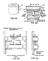
- Figures 2A, 2B and 2C show other examples.
- a suitable gas-generating cartridge 40 is shown.
- the cartridge 40 consists of a moulded plastic shell 42.
- the top-section is filled with bicarbonate pellets 44, the middle section with pellets containing a mixture of bicarbonate and powdered acid 46 and the lower section contains a liquid acid 48.
- the top and bottom sections are connected by a tube 50, which is sealed with foil 52 at the bottom and filter paper 54 at the top.
- the top and bottom of cartridge 40 are closed by sealing foil 56.
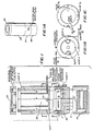
- FIG. 4 shows a sectional view of the carbonator tank.
- Lid (1) is removed and the tank filled with water up to a pre-determined mark.
- the reagent water tank (14) is filled at the same time, as soon as the water reaches the required level.
- lid (1) is replaced the top of the reagent water tank is sealed.
- valve 4 is opened by the pressure which lid (1) exerts on a spring valve actuator.
- the water in the reagent tank cannot as yet flow out, since it is restrained by a second valve (5).
- Lid (2) is removed and the gas generating cartridge 40 inserted. The cartridge 40 does not reach its lowest position, being restrained by an o-ring (6).
- the cartridge When lid (2) is replaced, the cartridge is punctured on the top foil 56 and forced to its lowest position. In its lowest position, the cartridge 40 seals its base (9) against o-ring (7) and its top section (10) against a seal (8).
- a spring bellows (13) enters the base of the cartridge displacing the acid into the top section.
- the spike (11) in the center of the bellows opens the channel to the top section through foil 52.
- valve (5) opens automatically and water from the reagent water chamber flows into the carbonating reagent section (12) of the cartridge. C02 gas is released and flows to sparge tubes 60, carbonating the water to the level pre-determined by the quantity of chemicals.
- the spring bellows (13) has forced acid in contact with bicarbonate and this also generates CO2, pressurizing the head-space of the tank. As soon as the head-space pressure has reached equilibrium with the spring pressure in the bellows, the spring contracts, the acid returns to the lower chamber and the reaction stops. Thereafter, the process repeats itself, whenever water is drawn out of the carbonator and the head-pressure drops.
- FIGS 5A and 5B show a typical installation of a horizontal carbonator tank in a refrigerator.
- the tank can now be connected to a dispensing point within or outside the refrigerator.
- the above principles can also be applied to a vertical carbonator. They also illustrate how a liquid acid may also be used, in place of a solid acid, and how an external fixed pressure reference may be applied in place of the self-generated internal reference as described in Figures 1 and 2.
- the external pressure reference can be by spring pressure (as above), or by an air-cushion or by a membrane or by a piston or by some other similar pressure-exerting device.
Landscapes
- Chemical & Material Sciences (AREA)
- Chemical Kinetics & Catalysis (AREA)
- Non-Alcoholic Beverages (AREA)
- Devices For Dispensing Beverages (AREA)
- Water Treatment By Sorption (AREA)
- Electrical Discharge Machining, Electrochemical Machining, And Combined Machining (AREA)
- Feeding, Discharge, Calcimining, Fusing, And Gas-Generation Devices (AREA)
- External Artificial Organs (AREA)
Priority Applications (1)
| Application Number | Priority Date | Filing Date | Title |
|---|---|---|---|
| AT88117098T ATE92363T1 (de) | 1987-10-15 | 1988-10-14 | Tragbare, automatische vorrichtung zum anreichern von wasser mit kohlensaeure ohne elektrische bauteile. |
Applications Claiming Priority (2)
| Application Number | Priority Date | Filing Date | Title |
|---|---|---|---|
| US10868487A | 1987-10-15 | 1987-10-15 | |
| US108684 | 1987-10-15 |
Publications (2)
| Publication Number | Publication Date |
|---|---|
| EP0312080A1 true EP0312080A1 (de) | 1989-04-19 |
| EP0312080B1 EP0312080B1 (de) | 1993-08-04 |
Family
ID=22323528
Family Applications (1)
| Application Number | Title | Priority Date | Filing Date |
|---|---|---|---|
| EP88117098A Expired - Lifetime EP0312080B1 (de) | 1987-10-15 | 1988-10-14 | Tragbare, automatische Vorrichtung zum Anreichern von Wasser mit Kohlensäure ohne elektrische Bauteile |
Country Status (6)
| Country | Link |
|---|---|
| EP (1) | EP0312080B1 (de) |
| JP (1) | JPH01139128A (de) |
| CN (1) | CN1019172B (de) |
| AT (1) | ATE92363T1 (de) |
| AU (1) | AU606220B2 (de) |
| DE (1) | DE3882879T2 (de) |
Families Citing this family (4)
| Publication number | Priority date | Publication date | Assignee | Title |
|---|---|---|---|---|
| MX2012008857A (es) | 2010-02-01 | 2012-12-05 | Green Mountain Coffee Roasters Inc | Metodo y aparato para carbonatacion de bebidas a basadas en cartuchos. |
| US9936834B2 (en) | 2010-02-01 | 2018-04-10 | Bedford Systems Llc | Method and apparatus for cartridge-based carbonation of beverages |
| US9700852B2 (en) * | 2012-08-28 | 2017-07-11 | So Spark Ltd. | System, method and capsules for producing sparkling drinks |
| US9382119B2 (en) | 2014-01-27 | 2016-07-05 | So Spark Ltd. | Rapid high-pressure microwave thermal decomposition system, capsule and method for using same |
Citations (5)
| Publication number | Priority date | Publication date | Assignee | Title |
|---|---|---|---|---|
| DE7114C (de) * | O. ZWIETUSCH in Mihvaukee im Staate Wisconsin, N.-A | Automatische Kohlensäure - Entwickelungs-Apparat für hohen Druck | ||
| DE45734C (de) * | G. F. GRAF in Hanau a. Main | Kohlensäure-Entwickler mit selbsttätiger Druckregulirung | ||
| US4304736A (en) * | 1980-01-29 | 1981-12-08 | The Coca-Cola Company | Method of and apparatus for making and dispensing a carbonated beverage utilizing propellant carbon dioxide gas for carbonating |
| GB2139910A (en) * | 1983-05-17 | 1984-11-21 | Thorn Emi Domestic Appliances | Carbonating apparatus |
| EP0168990A2 (de) * | 1984-07-12 | 1986-01-22 | Kenwood Limited | Karbonisierapparat |
Family Cites Families (1)
| Publication number | Priority date | Publication date | Assignee | Title |
|---|---|---|---|---|
| JPS5825053B2 (ja) * | 1979-07-24 | 1983-05-25 | 工業技術院長 | 高圧高温印加によるチオ・ニツケル・フエライト(NiFe↓2S↓4)の製造方法 |
-
1988
- 1988-10-14 EP EP88117098A patent/EP0312080B1/de not_active Expired - Lifetime
- 1988-10-14 CN CN88108527A patent/CN1019172B/zh not_active Expired
- 1988-10-14 AT AT88117098T patent/ATE92363T1/de not_active IP Right Cessation
- 1988-10-14 JP JP63257386A patent/JPH01139128A/ja active Granted
- 1988-10-14 DE DE88117098T patent/DE3882879T2/de not_active Expired - Fee Related
- 1988-10-17 AU AU23918/88A patent/AU606220B2/en not_active Ceased
Patent Citations (5)
| Publication number | Priority date | Publication date | Assignee | Title |
|---|---|---|---|---|
| DE7114C (de) * | O. ZWIETUSCH in Mihvaukee im Staate Wisconsin, N.-A | Automatische Kohlensäure - Entwickelungs-Apparat für hohen Druck | ||
| DE45734C (de) * | G. F. GRAF in Hanau a. Main | Kohlensäure-Entwickler mit selbsttätiger Druckregulirung | ||
| US4304736A (en) * | 1980-01-29 | 1981-12-08 | The Coca-Cola Company | Method of and apparatus for making and dispensing a carbonated beverage utilizing propellant carbon dioxide gas for carbonating |
| GB2139910A (en) * | 1983-05-17 | 1984-11-21 | Thorn Emi Domestic Appliances | Carbonating apparatus |
| EP0168990A2 (de) * | 1984-07-12 | 1986-01-22 | Kenwood Limited | Karbonisierapparat |
Also Published As
| Publication number | Publication date |
|---|---|
| CN1033751A (zh) | 1989-07-12 |
| DE3882879D1 (de) | 1993-09-09 |
| AU2391888A (en) | 1989-06-08 |
| CN1019172B (zh) | 1992-11-25 |
| JPH01139128A (ja) | 1989-05-31 |
| JPH0446610B2 (de) | 1992-07-30 |
| EP0312080B1 (de) | 1993-08-04 |
| ATE92363T1 (de) | 1993-08-15 |
| AU606220B2 (en) | 1991-01-31 |
| DE3882879T2 (de) | 1994-03-17 |
Similar Documents
| Publication | Publication Date | Title |
|---|---|---|
| US5182084A (en) | Portable automatic water carbonator | |
| US8317884B2 (en) | Hydrogen generating fuel cell cartridges | |
| CN1025008C (zh) | 用于充碳酸气饮料配出器的气体发生器 | |
| EP0312078B1 (de) | Apparatur zum chemischen Erzengung und Entnahme von Gasen | |
| US5192513A (en) | High speed process and apparatus for carbonating water | |
| KR100545104B1 (ko) | 압력을 받아서 액체를 분배하는 장치 | |
| EP2775189B1 (de) | Brennstoffzellenkartuschen zur Wasserstofferzeugung | |
| US5035351A (en) | Method and apparatus for maintaining a pressure within a product dispenser | |
| US5333763A (en) | Pressure activation device | |
| US4093681A (en) | Motorless carbonator | |
| CA2034069A1 (en) | Method and apparatus for maintaining a pressure within a product dispenser | |
| US5106597A (en) | Disposable gas generator cartridge and vessel therefor for use in a beverage dispenser | |
| US4839107A (en) | Microgravity carbonator system | |
| EP0312080A1 (de) | Tragbare, automatische Vorrichtung zum Anreichern von Wasser mit Kohlensäure ohne elektrische Bauteile | |
| US5188257A (en) | Supply of controlled, medium-pressure carbon dioxide gas in simple, convenient disposable packaging | |
| US5270069A (en) | Method for supplying carbonating gas to a beverage container | |
| EP2274230B1 (de) | Mit einem chemischen druckerzeuger versehene getränkezapfvorrichtung | |
| WO1993010022A1 (en) | A pressurised container | |
| US5186902A (en) | Supply of controlled, medium-pressure CO2 gas in simple, convenient disposable packaging | |
| JPH0551076A (ja) | 圧力容器 | |
| JP2007063029A (ja) | 水素発生装置及び水素発生方法 | |
| TH27832C3 (th) | อุปกรณ์สำหรับจ่ายของไหล | |
| TH41403A3 (th) | อุปกรณ์สำหรับจ่ายของไหล |
Legal Events
| Date | Code | Title | Description |
|---|---|---|---|
| PUAI | Public reference made under article 153(3) epc to a published international application that has entered the european phase |
Free format text: ORIGINAL CODE: 0009012 |
|
| AK | Designated contracting states |
Kind code of ref document: A1 Designated state(s): AT CH DE FR GB IT LI LU SE |
|
| 17P | Request for examination filed |
Effective date: 19890905 |
|
| 17Q | First examination report despatched |
Effective date: 19910802 |
|
| GRAA | (expected) grant |
Free format text: ORIGINAL CODE: 0009210 |
|
| AK | Designated contracting states |
Kind code of ref document: B1 Designated state(s): AT CH DE FR GB IT LI LU SE |
|
| REF | Corresponds to: |
Ref document number: 92363 Country of ref document: AT Date of ref document: 19930815 Kind code of ref document: T |
|
| ITF | It: translation for a ep patent filed | ||
| REF | Corresponds to: |
Ref document number: 3882879 Country of ref document: DE Date of ref document: 19930909 |
|
| ET | Fr: translation filed | ||
| EPTA | Lu: last paid annual fee | ||
| PLBE | No opposition filed within time limit |
Free format text: ORIGINAL CODE: 0009261 |
|
| STAA | Information on the status of an ep patent application or granted ep patent |
Free format text: STATUS: NO OPPOSITION FILED WITHIN TIME LIMIT |
|
| 26N | No opposition filed | ||
| EAL | Se: european patent in force in sweden |
Ref document number: 88117098.9 |
|
| PGFP | Annual fee paid to national office [announced via postgrant information from national office to epo] |
Ref country code: LU Payment date: 19950901 Year of fee payment: 8 |
|
| PGFP | Annual fee paid to national office [announced via postgrant information from national office to epo] |
Ref country code: SE Payment date: 19950918 Year of fee payment: 8 |
|
| PG25 | Lapsed in a contracting state [announced via postgrant information from national office to epo] |
Ref country code: LU Free format text: LAPSE BECAUSE OF NON-PAYMENT OF DUE FEES Effective date: 19961014 |
|
| PG25 | Lapsed in a contracting state [announced via postgrant information from national office to epo] |
Ref country code: SE Effective date: 19961015 |
|
| EUG | Se: european patent has lapsed |
Ref document number: 88117098.9 |
|
| PGFP | Annual fee paid to national office [announced via postgrant information from national office to epo] |
Ref country code: CH Payment date: 20010917 Year of fee payment: 14 |
|
| PGFP | Annual fee paid to national office [announced via postgrant information from national office to epo] |
Ref country code: AT Payment date: 20010925 Year of fee payment: 14 |
|
| PGFP | Annual fee paid to national office [announced via postgrant information from national office to epo] |
Ref country code: FR Payment date: 20011011 Year of fee payment: 14 |
|
| REG | Reference to a national code |
Ref country code: GB Ref legal event code: IF02 |
|
| PG25 | Lapsed in a contracting state [announced via postgrant information from national office to epo] |
Ref country code: AT Free format text: LAPSE BECAUSE OF NON-PAYMENT OF DUE FEES Effective date: 20021014 |
|
| PG25 | Lapsed in a contracting state [announced via postgrant information from national office to epo] |
Ref country code: LI Free format text: LAPSE BECAUSE OF NON-PAYMENT OF DUE FEES Effective date: 20021031 Ref country code: CH Free format text: LAPSE BECAUSE OF NON-PAYMENT OF DUE FEES Effective date: 20021031 |
|
| REG | Reference to a national code |
Ref country code: CH Ref legal event code: PL |
|
| PG25 | Lapsed in a contracting state [announced via postgrant information from national office to epo] |
Ref country code: FR Free format text: LAPSE BECAUSE OF NON-PAYMENT OF DUE FEES Effective date: 20030630 |
|
| REG | Reference to a national code |
Ref country code: FR Ref legal event code: ST |
|
| PGFP | Annual fee paid to national office [announced via postgrant information from national office to epo] |
Ref country code: GB Payment date: 20051003 Year of fee payment: 18 |
|
| PG25 | Lapsed in a contracting state [announced via postgrant information from national office to epo] |
Ref country code: IT Free format text: LAPSE BECAUSE OF NON-PAYMENT OF DUE FEES;WARNING: LAPSES OF ITALIAN PATENTS WITH EFFECTIVE DATE BEFORE 2007 MAY HAVE OCCURRED AT ANY TIME BEFORE 2007. THE CORRECT EFFECTIVE DATE MAY BE DIFFERENT FROM THE ONE RECORDED. Effective date: 20051014 |
|
| PGFP | Annual fee paid to national office [announced via postgrant information from national office to epo] |
Ref country code: DE Payment date: 20051014 Year of fee payment: 18 |
|
| PG25 | Lapsed in a contracting state [announced via postgrant information from national office to epo] |
Ref country code: DE Free format text: LAPSE BECAUSE OF NON-PAYMENT OF DUE FEES Effective date: 20070501 |
|
| GBPC | Gb: european patent ceased through non-payment of renewal fee |
Effective date: 20061014 |
|
| PG25 | Lapsed in a contracting state [announced via postgrant information from national office to epo] |
Ref country code: GB Free format text: LAPSE BECAUSE OF NON-PAYMENT OF DUE FEES Effective date: 20061014 |