EP0312093A2 - Méthode de fabrication d'une buse d'injection avec, soudé dans le point, un élément de chauffage mis à la masse - Google Patents
Méthode de fabrication d'une buse d'injection avec, soudé dans le point, un élément de chauffage mis à la masse Download PDFInfo
- Publication number
- EP0312093A2 EP0312093A2 EP88117128A EP88117128A EP0312093A2 EP 0312093 A2 EP0312093 A2 EP 0312093A2 EP 88117128 A EP88117128 A EP 88117128A EP 88117128 A EP88117128 A EP 88117128A EP 0312093 A2 EP0312093 A2 EP 0312093A2
- Authority
- EP
- European Patent Office
- Prior art keywords
- heating element
- forward end
- main body
- rear end
- bore
- Prior art date
- Legal status (The legal status is an assumption and is not a legal conclusion. Google has not performed a legal analysis and makes no representation as to the accuracy of the status listed.)
- Withdrawn
Links
- 238000010438 heat treatment Methods 0.000 title claims abstract description 118
- 238000001746 injection moulding Methods 0.000 title claims abstract description 16
- 238000004519 manufacturing process Methods 0.000 title claims abstract description 9
- 238000005219 brazing Methods 0.000 claims abstract description 27
- 229910000831 Steel Inorganic materials 0.000 claims abstract description 23
- 239000010959 steel Substances 0.000 claims abstract description 23
- PXHVJJICTQNCMI-UHFFFAOYSA-N Nickel Chemical compound [Ni] PXHVJJICTQNCMI-UHFFFAOYSA-N 0.000 claims abstract description 22
- 239000000843 powder Substances 0.000 claims abstract description 18
- 229910000997 High-speed steel Inorganic materials 0.000 claims abstract description 15
- 229910052759 nickel Inorganic materials 0.000 claims abstract description 10
- 238000005260 corrosion Methods 0.000 claims abstract description 8
- 230000007797 corrosion Effects 0.000 claims abstract description 8
- 239000011324 bead Substances 0.000 claims abstract description 5
- 238000003780 insertion Methods 0.000 claims abstract description 4
- 230000037431 insertion Effects 0.000 claims abstract description 4
- 239000000155 melt Substances 0.000 claims description 21
- 238000000034 method Methods 0.000 claims description 17
- 239000000463 material Substances 0.000 claims description 14
- 238000007789 sealing Methods 0.000 claims description 10
- 239000011230 binding agent Substances 0.000 claims description 8
- 239000011248 coating agent Substances 0.000 claims description 8
- 238000000576 coating method Methods 0.000 claims description 8
- 239000011810 insulating material Substances 0.000 claims description 8
- 238000005553 drilling Methods 0.000 claims description 4
- 238000003754 machining Methods 0.000 claims description 4
- 230000001681 protective effect Effects 0.000 claims description 4
- 238000004804 winding Methods 0.000 claims description 4
- 238000005304 joining Methods 0.000 claims description 3
- 238000003466 welding Methods 0.000 claims description 3
- 230000006872 improvement Effects 0.000 claims description 2
- 239000011253 protective coating Substances 0.000 abstract description 5
- 239000004923 Acrylic lacquer Substances 0.000 abstract description 3
- 229910000990 Ni alloy Inorganic materials 0.000 description 13
- 238000009413 insulation Methods 0.000 description 5
- 239000000523 sample Substances 0.000 description 4
- 239000000919 ceramic Substances 0.000 description 3
- 238000002347 injection Methods 0.000 description 3
- 239000007924 injection Substances 0.000 description 3
- 239000004922 lacquer Substances 0.000 description 3
- XKRFYHLGVUSROY-UHFFFAOYSA-N Argon Chemical compound [Ar] XKRFYHLGVUSROY-UHFFFAOYSA-N 0.000 description 2
- IJGRMHOSHXDMSA-UHFFFAOYSA-N Atomic nitrogen Chemical compound N#N IJGRMHOSHXDMSA-UHFFFAOYSA-N 0.000 description 2
- 230000009471 action Effects 0.000 description 2
- 239000012671 ceramic insulating material Substances 0.000 description 2
- 238000001816 cooling Methods 0.000 description 2
- 239000007788 liquid Substances 0.000 description 2
- 238000000465 moulding Methods 0.000 description 2
- 239000011295 pitch Substances 0.000 description 2
- RTAQQCXQSZGOHL-UHFFFAOYSA-N Titanium Chemical compound [Ti] RTAQQCXQSZGOHL-UHFFFAOYSA-N 0.000 description 1
- 229910001315 Tool steel Inorganic materials 0.000 description 1
- 238000005273 aeration Methods 0.000 description 1
- 229910045601 alloy Inorganic materials 0.000 description 1
- 239000000956 alloy Substances 0.000 description 1
- 229910052786 argon Inorganic materials 0.000 description 1
- 230000000712 assembly Effects 0.000 description 1
- 238000000429 assembly Methods 0.000 description 1
- QVGXLLKOCUKJST-UHFFFAOYSA-N atomic oxygen Chemical compound [O] QVGXLLKOCUKJST-UHFFFAOYSA-N 0.000 description 1
- 230000001680 brushing effect Effects 0.000 description 1
- 229910010293 ceramic material Inorganic materials 0.000 description 1
- 239000004020 conductor Substances 0.000 description 1
- 239000000498 cooling water Substances 0.000 description 1
- 239000002178 crystalline material Substances 0.000 description 1
- 230000001419 dependent effect Effects 0.000 description 1
- 238000007598 dipping method Methods 0.000 description 1
- 238000005485 electric heating Methods 0.000 description 1
- 239000011261 inert gas Substances 0.000 description 1
- CPLXHLVBOLITMK-UHFFFAOYSA-N magnesium oxide Inorganic materials [Mg]=O CPLXHLVBOLITMK-UHFFFAOYSA-N 0.000 description 1
- 239000000395 magnesium oxide Substances 0.000 description 1
- AXZKOIWUVFPNLO-UHFFFAOYSA-N magnesium;oxygen(2-) Chemical compound [O-2].[Mg+2] AXZKOIWUVFPNLO-UHFFFAOYSA-N 0.000 description 1
- 238000002844 melting Methods 0.000 description 1
- 230000008018 melting Effects 0.000 description 1
- 229910052751 metal Inorganic materials 0.000 description 1
- 239000002184 metal Substances 0.000 description 1
- 150000002739 metals Chemical class 0.000 description 1
- 238000002156 mixing Methods 0.000 description 1
- 238000012986 modification Methods 0.000 description 1
- 230000004048 modification Effects 0.000 description 1
- 229910052757 nitrogen Inorganic materials 0.000 description 1
- 239000001301 oxygen Substances 0.000 description 1
- 229910052760 oxygen Inorganic materials 0.000 description 1
- 230000008569 process Effects 0.000 description 1
- 238000005086 pumping Methods 0.000 description 1
- 238000007711 solidification Methods 0.000 description 1
- 230000008023 solidification Effects 0.000 description 1
- 238000005507 spraying Methods 0.000 description 1
- 239000010936 titanium Substances 0.000 description 1
- 229910052719 titanium Inorganic materials 0.000 description 1
Images




Classifications
-
- B—PERFORMING OPERATIONS; TRANSPORTING
- B29—WORKING OF PLASTICS; WORKING OF SUBSTANCES IN A PLASTIC STATE IN GENERAL
- B29C—SHAPING OR JOINING OF PLASTICS; SHAPING OF MATERIAL IN A PLASTIC STATE, NOT OTHERWISE PROVIDED FOR; AFTER-TREATMENT OF THE SHAPED PRODUCTS, e.g. REPAIRING
- B29C45/00—Injection moulding, i.e. forcing the required volume of moulding material through a nozzle into a closed mould; Apparatus therefor
- B29C45/17—Component parts, details or accessories; Auxiliary operations
- B29C45/26—Moulds
- B29C45/27—Sprue channels ; Runner channels or runner nozzles
- B29C45/2737—Heating or cooling means therefor
-
- B—PERFORMING OPERATIONS; TRANSPORTING
- B23—MACHINE TOOLS; METAL-WORKING NOT OTHERWISE PROVIDED FOR
- B23P—METAL-WORKING NOT OTHERWISE PROVIDED FOR; COMBINED OPERATIONS; UNIVERSAL MACHINE TOOLS
- B23P15/00—Making specific metal objects by operations not covered by a single other subclass or a group in this subclass
- B23P15/007—Making specific metal objects by operations not covered by a single other subclass or a group in this subclass injection moulding tools
-
- B—PERFORMING OPERATIONS; TRANSPORTING
- B29—WORKING OF PLASTICS; WORKING OF SUBSTANCES IN A PLASTIC STATE IN GENERAL
- B29C—SHAPING OR JOINING OF PLASTICS; SHAPING OF MATERIAL IN A PLASTIC STATE, NOT OTHERWISE PROVIDED FOR; AFTER-TREATMENT OF THE SHAPED PRODUCTS, e.g. REPAIRING
- B29C45/00—Injection moulding, i.e. forcing the required volume of moulding material through a nozzle into a closed mould; Apparatus therefor
- B29C45/17—Component parts, details or accessories; Auxiliary operations
- B29C45/26—Moulds
- B29C45/27—Sprue channels ; Runner channels or runner nozzles
- B29C45/278—Nozzle tips
- B29C2045/2782—Nozzle tips metallurgically bonded to the nozzle body
-
- Y—GENERAL TAGGING OF NEW TECHNOLOGICAL DEVELOPMENTS; GENERAL TAGGING OF CROSS-SECTIONAL TECHNOLOGIES SPANNING OVER SEVERAL SECTIONS OF THE IPC; TECHNICAL SUBJECTS COVERED BY FORMER USPC CROSS-REFERENCE ART COLLECTIONS [XRACs] AND DIGESTS
- Y10—TECHNICAL SUBJECTS COVERED BY FORMER USPC
- Y10T—TECHNICAL SUBJECTS COVERED BY FORMER US CLASSIFICATION
- Y10T29/00—Metal working
- Y10T29/49—Method of mechanical manufacture
- Y10T29/49002—Electrical device making
- Y10T29/49082—Resistor making
- Y10T29/49083—Heater type
Definitions
- This invention relates generally to injection molding and more particularly to a method of making an improved injection molding nozzle having an integral electrical heating element wherein the forward end of the heating element is brazed into the nose portion to ground it and heat the forward end of the nozzle.
- Nozzles with integral heating elements are well known in the art.
- the applicant's recent Canadian patent application serial number 542,185 entitled “Coated Injection Molding Nozzle and Method” filed July 15, 1987 and U.S. application 086,621 filed August 18, 1987 disclose a nozzle in which the forward end of the heating element extends into the nose portion.
- an object of the present invention to at least partially overcome the disadvantages of the prior art by providing a method of making an injection molding nozzle having a single heating element, the forward end of which is brazed in an electrically conductive material adjacent the forward end of the nozzle at the same time as the other components of the nozzle are integrally brazed together.
- the invention provides a method of making an integral elongated injection molding heated nozzle having a forward end and a rear end with a steel central portion having a generally cylindrical outer surface extending between a steel collar portion adjacent the rear end and a nose portion having a tapered outer surface adjacent the forward end, the nozzle having a melt bore with first and second portions, the first portion extending centrally from the rear end through the central portion and joining the second portion which extends diagonally to the tapered surface of the nose portion, the nozzle having an electrically insulated heating element with a rear end and a forward end, the heating element having one portion extending diagonally into the nose portion to the forward end of the heating element and another portion integrally brazed in a spiral channel in the cylindrical outer surface of the central portion, the rear end of the heating element extending out through an opening in the collar portion to a cold terminal, the heating element having a resistance wire extending centrally through an electrical insulating material in an outer casing, including forming an elongated steel main
- FIG. 1 shows a portion of a multi-cavity injection molding system wherein a number of heated nozzles 10 extend from a common elongated heated manifold 12. Each heated nozzle 10 is seated in a well 14 in a cavity plate 16.
- the nozzle 10 has a steel central portion 18 with a generally cylindrical outer surface 20 extending between a steel collar portion 22 adjacent the rear end 24 and a steel elongated nose portion 26 adjacent the forward end 28.
- the nose portion 26 has a tapered outer surface 30 which leads to a pointed tip 32 at the forward end 28 which is in alignment with a gate 34 in the cavity plate 16 leading to a cavity 36.
- the nozzle 10 is seated in this position in the well 14 by a circumferential insulation flange or bushing 38 which extends from the collar portion 22 and sits on a circumferential shoulder 40.
- the nozzle is accurately located with the pointed tip 32 in alignment with the gate 34 by a circumferential sealing and locating flange 42 which extends between the central portion 18 and the nose portion 26 to abut against the inner surface 44 of the well 14.
- the heated nozzle 10 is separated from the surrounding cooled cavity plate 16 by an insulative air space 46.
- Each nozzle 10 is fastened by bolts 48 to the manifold 12 which is secured between the cavity plate 16 and a top clamp plate 50 by a locating ring 52 and a titanium pressure pad 54.
- the back plate 50 is held in place by bolts 56 which extend into the cavity plate 16.
- the back plate 50 and the cavity plate 16 are cooled by pumping cooling water through cooling conduits 58.
- the manifold 12 is heated by an electric heating element 60 which is cast into it as described in the applicant's U.S. patent number 4,688,622 entitled "Injection Molding Manifold Member and Method of Manufacture" which issued August 25, 1987.
- the locating ring 52 provides another insulative air space 62 between the heated manifold 12 and the cooled cavity plate 16.
- the manifold 12 has a melt passage 64 which branches from a common inlet to a number of outlets 66 on the opposite side. Each outlet is in alignment with an inlet 68 to a melt bore 70 extending through one of the nozzles. Each melt bore 70 has a central portion 72 extending from the rear end 24 and a diagonal portion 74, which connects to the tapered surface 30 of the nose portion 26.
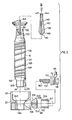
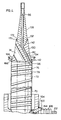
- the nozzle 10 is heated by an electrically insulated heating element 76 which is integrally brazed in a spiral channel 78 in the cylindrical outer surface 20 of the central portion 18.
- the heating element 76 in the channel 78 and the outer surface 20 are covered with a protective nickel coating 80 as described in the applicant's Canadian patent application serial number 542,185, mentioned above.
- the heating element 76 also has a portion 82 which extends diagonally into the nose portion 26 of the nozzle 10 beneath the circumferential sealing and locating flange 42 and then centrally to a forward end 84 adjacent the pointed tip 32.
- the low voltage single wire heating element 76 has a nickel-chrome resistance wire 86 extending centrally through a refractory powder electrical insulating material 88 such as magnesium oxide inside a steel casing 90.
- the exposed resistance wire 86 projects from the insulating material 88 and casing 90 to a high speed steel insert portion 92 which forms the pointed tip 32.
- the exposed wire 86 and the high speed steel insert portion 92 are integrally brazed in nickel 94 which grounds the heating element 76 adjacent the pointed tip. This provides a pointed tip 32 which is corrosion and wear resistant and which can be heated by the heating element 76 to a predetermined temperature.
- the heating element 76 has a rear end 96 which extends out through a central bore 98 in a plug 100 received in the collar portion 22.
- the resistance wire 86 at the rear end 96 of the heating element 76 connects to a threaded stud 102 surrounded by ceramic insulation 104 inside a cylindrical steel sleeve 106 which is attached to the surface 108 of the plug 100.
- a ceramic washer 110 and a steel washer 112 are received on the projecting stud 102 to form a cold terminal 114 which receives an external power lead 116 which is held securely in place by nut 118.
- electrical current from the lead 116 flows through the heating element 76 to the ground at the forward end 84.
- thermocouple hole 120 which is drilled diagonally from the outer surface 20 of the central portion 18 beneath the sealing and locating flange 42. As seen in Figure 2, this hole 120 removably receives a thermocouple 122 which extends through the air space 46 to measure the temperature during use.
- the space 124 remains filled with melt, a portion of which solidifies adjacent the cooled cavity plate 16, and the sealing and locating flange 42 prevents it escaping into the insulative air space 46.
- injection pressure is held momentarily to pack and then released.
- the mold is opened to eject the molded products.
- the mold is closed and injection pressure is reapplied to refill the cavity. This cycle is continuously repeated with a frequency dependent on the size and shape of the cavities and the type of material being molded.
- temperature assisted gating can be employed. This involves controlling the flow of power to the leads 116 to the heating elements 76 in a co-ordinated cycle so that no heat is provided to the nozzles for a short period of time before and when the mold is opened.
- the elongated shape of each tapered nose portion 26 surrounded by the cooled cavity plate 16 results in a temperature drop in the gate area of approximately 7-8°C/second. For most crystaline materials, a temperature drop of 20-25 C is sufficient to freeze the gate prior to ejection.
- the central portion 18 of the nozzle 10 must have sufficient mass to retain heat, while the nose portion 26 must be sufficiently tapered and elongated and the forward end 84 of the heating element 76 brazed close enough to the pointed tip 32 that gate temperature can be lowered and raised relatively quickly.
- An elongated main body 126 is cast of a tool steel such as H13 with a central portion 18 having a cylindrical outer surface 20 extending between a smaller diameter neck portion 128 at the rear end 24 and a tapered portion 130 leading to the recessed forward end 132 of the main body 126.
- a spiral channel 78 having varying pitches accordng to a predetermined configuration is cast in the cylindrical outer surface 20 of the central portion 18.
- the central portion 72 of the melt bore 70 s drilled from the rear end 24 to join the diagonal portion 74 which is drilled in the tapered portion 130.
- a smaller diameter heating element bore 134 is drilled diagonally in the tapered portion 130 to connect to the end 136 of the spiral channel 78.
- a thermocouple hole 120 is drilled diagonally beneath the locating and sealing flange 42 to receive the thermocouple 122 during use.
- the hole 120 is covered by a protective material to keep the nickel out during brazing.
- An elongated tip portion 138 is formed of high speed steel to have an outer surface 140 which tapers from a larger diameter rear end 142 to a smaller diameter forward end 144.
- a heating element bore 146 is drilled centrally through the tip portion 138 and machined adjacent the forward end 144 to form a larger diameter mouth 147.
- the outer surface 140 is cylndrical around the mouth 147 at the forward end 144 where it is later machined.
- the rear end 142 of the tip portion 138 has a beveled surface 148 which matches the recessed forward end 132 of the main body 126.
- a cylindrical collar portion 22, a tapered plug 100 and a sleeve 106 are also made of a suitable steel, such as H13.
- the collar portion has a central opening 149 therethrough to snugly receive the neck portion 128 of the main body 126.
- the collar portion 22 is made with a circumferential insulation flange 38 which extends forward and is somewhat larger in diameter than the outer surface 20 of the central portion 18 to form an insulative air space between them.
- a tapered surface 150 leading to the central opening 149 matches a tapered surface 152 between the neck portion 128 and the cylindrical outer surface 20 of the central porton 18 of the main body 126.
- the collar portion 22 also has a radial openng 154 extending outwardly therethrough from the central opening 149.
- the radial opening has a tapered surface 156 to receive the tapered plug 100 which has a central heating element bore 98 extending therethrough.
- the plug 100 has an outer surface 108 which receives the sleeve 106.
- the outer casing 90 and the insulating material 88 are stripped adjacent the forward end 84 of the heating element 76 to expose approximately 0.3 mm. of the resistance wire 86.
- One portion 82 of the heating element 76 is then inserted through the diagonal heating element bore 134 until the forward end 84 projects a predetermined distance depending on the length of the tip portion 138.
- Another portion 158 of the heating element 76 is then wound in the spiral channel 78 with the rear end 96 of the heating element projecting adjacent the rear end 24 of the main body 126, as seen in Figure 3.
- the plug 100 is then inserted over the projecting rear end 96 of the heating element and located firmly in place in the tapered opening 154.
- the heating element 76 fits snugly in the hole 98 through the plug 100, this bends the heating element to a position wherein the rear end 96 of the heating element projects past the surface 108 of the plug 100.
- This projecting portion is then stripped of the casing 90 and the insulation 88 and welded to a flat surface 160 of the threaded stud 102.
- the sleeve 106 is then located in place around a locating flange 162 on the surface 108 of the plug 100, and the plug 100 and sleeve 106 are tack welded to retain them in this position. Beads of nickel brazing paste 164 are later applied along where the plug 100 joins the collar portion 22 and where the sleeve 106 joins the surface 108 of the plug 100.
- the circumferential sealing and locating flange 42 is then inserted over the forward end 132 of the main body 126 to a position abutting against a locating shoulder 166.
- this steel flange 42 is slightly resilient to form a tight seal against the inner surface 44 of the well to contain the pressurized melt during use.
- a bead of brazing material 168 such as nickel paste is applied along where the flange 42 joins the main body 126.
- the tip portion 138 is then inserted in place over the projecting forward end 84 of the heating element 76.
- the beveled rear end 142 is accurately located in the recessed forward end 132 of the main body 126 and they are tack welded together to hold the tip portion 138 in place.
- the forward end 132 of the main body 126 is made sufficently larger in diameter than the rear end 142 of the tip portion 138 to form an inclined shoulder 170 where they join.
- Another bead 172 of nickel brazing paste is run along this inclined shoulder 170, from where it runs down between the rear end 142 of the tip portion 138 and the forward end 132 of the main body 126 when the assembly is brazed in the vacuum furnace 174.
- the assembly is sprayed with a binder such as acrylic lacquer 176 and then immersed in a bath of nickel alloy powder 178 which sticks to the lacquer to coat the surfaces of the central portion 18 and the collar portion 22.
- Plastic covers 180 are located over the tip portion 138 and sealing and locating flange 42 as well as sleeve 106 to prevent them being coated.
- the melt bore 70 is also coated by brushing lacquer in and then applying the powder.
- the binder 176 is preferably an acrylic lacquer which volatizes when heated in the vacuum furnace 174, other suitable binders may be used.
- the powder 178 is preferably nickel or an alloy thereof, but other suitable metals which form a conductive and protective coating may be used.
- the powder 178 is agitated by aeration from the bottom 182 to provide a fluidized bath to ensure the assembly is completed coated. While the preferred method is to apply this coating by successively spraying the assembly with the liquid and then dipping it in the powder, it can be applied in one step by mixing the powder in the liquid before application. After the coating has been applied, the assembly is oriented with the forward end 28 upright and the high speed steel insert portion 92 is inserted into the mouth 147 at the forward end 144 of the tip portion 138. As best seen in Figure 7, the insert portion 92 drops into the heating element bore 146 and rests against the exposed wire 86 at the forward end 84 of the heating element 76.
- a predetermined quantity of nickel alloy powder 184 is inserted into the mouth 147 on top of the high speed steel insert portion 92.
- the insert portion 92 has a square cross section so that it is located in the heating element bore 146, but has spaces between it and the surrounding bore.
- the coated assemblies are then loaded in batches into a vacuum furnace 174.
- the furnace is evacuated to a relatively high vacuum to remove substantially all the oxygen.
- the coating is heated, the binder is volatized, but the nickel alloy remains in place.
- the vacuum is reduced by partially backfilling with an inert gas such as argon or nitrogen.
- the nickel alloy melts, it flows by capilliary action around the roughened surface of the heating element 76 to completely fill the spiral channel 78 and integrally embed the heating element 76.
- the molten nickel alloy also flows into the space 186 around the neck portion 128 and the brazing paste 164 melts and flows around the plug 100 and the end of the sleeve 106.
- the brazing material 168 flows around the circumferential flange 42 and the brazing paste 172 melts and flows down between the rear end 142 of the tip portion 138 and the forward end 132 of the main body 126. These surfaces are roughened to promote capilliary flow of the nickel alloy between them.
- the nickel alloy powder 184 in the mouth 147 melts and flows down around the insert portion 92 to completely embed it as well as the exposed end of the wire 86.
- the tip portion 138 and the collar portion 22 are integrally brazed to the main body 126.
- the heating element 76 is brazed in the spiral channel 78 and the diagonal heating element bore 134 and the central bore 146 through the tip portion 138.
- the exposed wire 86 is electrically grounded in the surrounding nickel alloy adjacent the high speed steel insert portion 92 so that the forward end 28 of the nozzle 10 can be heated in a predetermined temperature.
- the nickel alloy powder on the surfaces of the assembly provides a complete protective coating 80 of nickel alloy having a substantially uniform thickness, including the surfaces of the melt bore 70. Brazing the assembly in a vacuum provides a metallurgical bonding of the nickel alloy to the steel which improves the efficiency of the heat transfer from the heating element 76 as well as the adherence of the protective coating.
- the pitch or heat profile of the heating element 76 varies along its length to provide more heat at the ends of the nozzle than in the middle where there is less heat loss.
- This profile can be precisely controlled for any particular application by varying the pattern of the spiral channel 78 which is cast in the outer surface 20 of the main body 126. Joining the components of the assembly together, forming the protective coating 80, grounding the forward end 84 of the heating element 76, and heat treating all in a single insertion in the vacuum furnace facilitates considerably the manufacture of an improved nozzle.
- the nozzles 10 are cooled and removed from the vacuum furnace 174, they are machined to form the tapered outer surface 30 of the nose portion 26 and the pointed tip 32.
- the pointed tip 32 is formed of high speed steel which is both corrosion and wear resistant which increases the operating life of the nozzle.
- the ceramic insulating material 104 is then poured into the sleeve 106 around the threaded stud 102. After the ceramic material has hardened, the ceramic washer 110 and steel washer 112 are located on the projecting stud 102 and the nut 118 attaches the electrical lead 116 during use.
- the exposed resistance wire 86 at the forward end of the heating element can be brazed in nickel alloy to form a pointed tip 32 without the use of a high speed steel insert portion 92.
- This also provides the nozzle with a pointed tip which is corrosion and wear resistant and can be heated to a predetermined temperature as described above.
- the tip portion 138 can have a different shape and the forward end 28 of the nozzle can be machined to have a different shape to provide a nozzle suitable for edge gating, as described in the applicant's Canadian patent application serial no. 549,518 entitled "Injection Molding Nozzle having Grounded Heating Element Brazed into pointed Tip" filed October 16, 1987. Reference is made to the appended claims for a definition of the invention.
Landscapes
- Engineering & Computer Science (AREA)
- Mechanical Engineering (AREA)
- Manufacturing & Machinery (AREA)
- Injection Moulding Of Plastics Or The Like (AREA)
- Moulds For Moulding Plastics Or The Like (AREA)
Applications Claiming Priority (2)
| Application Number | Priority Date | Filing Date | Title |
|---|---|---|---|
| CA000549517A CA1263222A (fr) | 1987-10-16 | 1987-10-16 | Methode de fabrication d'une buse de moulage par injection, son extremite pointue renfermant un element chauffant avec masse soude a meme |
| CA549517 | 1987-10-16 |
Publications (2)
| Publication Number | Publication Date |
|---|---|
| EP0312093A2 true EP0312093A2 (fr) | 1989-04-19 |
| EP0312093A3 EP0312093A3 (fr) | 1989-12-27 |
Family
ID=4136663
Family Applications (1)
| Application Number | Title | Priority Date | Filing Date |
|---|---|---|---|
| EP88117128A Withdrawn EP0312093A3 (fr) | 1987-10-16 | 1988-10-14 | Méthode de fabrication d'une buse d'injection avec, soudé dans le point, un élément de chauffage mis à la masse |
Country Status (6)
| Country | Link |
|---|---|
| US (1) | US4773154A (fr) |
| EP (1) | EP0312093A3 (fr) |
| JP (1) | JPH01136714A (fr) |
| CN (1) | CN1032516A (fr) |
| CA (1) | CA1263222A (fr) |
| DE (1) | DE3835104A1 (fr) |
Cited By (2)
| Publication number | Priority date | Publication date | Assignee | Title |
|---|---|---|---|---|
| EP0312092A3 (fr) * | 1987-10-16 | 1990-03-28 | Mold-Masters Limited | Buse d'injection comportant un élément de chauffage mis à la terre brasé dans une extrémité pointue |
| EP1151842A3 (fr) * | 1998-02-02 | 2002-07-17 | Mold-Masters Limited | Procédé de fabrication d'une buse en trois éléments de moulage par injection et de refroidir une cavité de moule |
Families Citing this family (15)
| Publication number | Priority date | Publication date | Assignee | Title |
|---|---|---|---|---|
| CA1261576A (fr) * | 1988-04-13 | 1989-09-26 | Jobst U. Gellert | Buse de moulage par injection a element de chauffage multicouche et methode de fabrication |
| CA1274368A (fr) * | 1988-06-17 | 1990-09-25 | Jobst Ulrich Gellert | Systeme de moulage par injection, avec bague isolante rapportee |
| CA1265916A (fr) * | 1988-09-30 | 1990-02-20 | Jobst Ulrich Gellert | Methode de fabrication d'une borne electrique sur un injecteur de moulage |
| CA1280268C (fr) * | 1988-09-30 | 1991-02-19 | Jobst Ulrich Gellert | Buse de moulage par injection a nez dont l'alesage est encercle par un element chauffant, et son fonctionnement |
| CA1268915A (fr) * | 1989-02-10 | 1990-05-15 | Jobst Ulrich Gellert | Buse de moulage par injection garnie de sondes conductives espacees a sa circonference |
| CA2008171C (fr) * | 1990-01-19 | 1997-05-20 | Jobst Ulrich Gellert | Methode de fabrication de tuyere de grosseur determinee, pour moule a injection |
| DE4032509C2 (de) * | 1990-10-12 | 1993-10-21 | Gellert Jobst U | Spritzgießdüse für eine Spritzgießeinrichtung |
| DE4032508A1 (de) * | 1990-10-12 | 1992-04-16 | Gellert Jobst U | Spritzgiessduese |
| US5527177A (en) * | 1994-06-07 | 1996-06-18 | Potter; Edward J. | Tip heater for a runnerless injection molding probe |
| JP4627712B2 (ja) * | 2005-10-07 | 2011-02-09 | 株式会社日立製作所 | 回転電機及びその製作方法 |
| US20110045124A1 (en) * | 2007-09-21 | 2011-02-24 | Mold-Masters (2007) Limited | Injection Molding Nozzle Having A Nozzle Tip With Diamond Crown |
| US20110008532A1 (en) * | 2007-12-21 | 2011-01-13 | Mold-Masters (2007) Limited | Method of manufacturing hot-runner component and hot-runner components thereof |
| TWI540038B (zh) * | 2009-05-07 | 2016-07-01 | Krauss Maffei Tech Gmbh | An injection molding machine, a control device for the injection molding machine, and a method of developing the temperature curve in the control device |
| US11231257B2 (en) * | 2010-11-10 | 2022-01-25 | True Velocity Ip Holdings, Llc | Method of making a metal injection molded ammunition cartridge |
| CN103551026A (zh) * | 2013-10-30 | 2014-02-05 | 中能东讯新能源科技(大连)有限公司 | 锅炉脱硝剂喷嘴防爆管结构 |
Family Cites Families (11)
| Publication number | Priority date | Publication date | Assignee | Title |
|---|---|---|---|---|
| CA542185A (fr) * | 1957-06-11 | Fred E. Cairns, Jr. | Systeme de commande de surete de bruleur de combustible utilisant une transmission de flamme | |
| JPS5227181B1 (fr) * | 1971-02-17 | 1977-07-19 | ||
| US4010351A (en) * | 1976-03-03 | 1977-03-01 | Rama Corporation | Cartridge heater with improved thermocouple |
| JPS6112089Y2 (fr) * | 1980-06-25 | 1986-04-16 | ||
| CA1174020A (fr) * | 1982-01-06 | 1984-09-11 | Jobst U. Gellert | Collecteur de moulage par injection, et methode de fabrication connexe |
| CA1177214A (fr) * | 1982-03-31 | 1984-11-06 | Jobst U. Gellert | Procede de moulage sous pression |
| JPS59142124A (ja) * | 1983-02-02 | 1984-08-15 | Shigeru Tsutsumi | 合成樹脂射出成形機用ホツトチツプブシング |
| GB2143440A (en) * | 1983-07-21 | 1985-02-13 | Morton Robert Dg Ltd | Mixers |
| CA1230458A (fr) * | 1984-07-13 | 1987-12-22 | Gellert, Jobst Ulrich | Buse chauffante de moulage par injection a element chauffant brase et methode de fabrication |
| JPS6158711A (ja) * | 1984-08-31 | 1986-03-26 | Shigeru Tsutsumi | 尖鋭発熱体 |
| CA1267514A (fr) * | 1987-07-15 | 1990-04-10 | Jobst Ulrich Gellert | Buse d'injection a revetement pour le moulage |
-
1987
- 1987-10-16 CA CA000549517A patent/CA1263222A/fr not_active Expired
- 1987-11-30 US US07/127,773 patent/US4773154A/en not_active Expired - Fee Related
-
1988
- 1988-10-13 CN CN88107004A patent/CN1032516A/zh active Pending
- 1988-10-14 DE DE3835104A patent/DE3835104A1/de not_active Ceased
- 1988-10-14 EP EP88117128A patent/EP0312093A3/fr not_active Withdrawn
- 1988-10-15 JP JP63260367A patent/JPH01136714A/ja active Pending
Cited By (2)
| Publication number | Priority date | Publication date | Assignee | Title |
|---|---|---|---|---|
| EP0312092A3 (fr) * | 1987-10-16 | 1990-03-28 | Mold-Masters Limited | Buse d'injection comportant un élément de chauffage mis à la terre brasé dans une extrémité pointue |
| EP1151842A3 (fr) * | 1998-02-02 | 2002-07-17 | Mold-Masters Limited | Procédé de fabrication d'une buse en trois éléments de moulage par injection et de refroidir une cavité de moule |
Also Published As
| Publication number | Publication date |
|---|---|
| US4773154A (en) | 1988-09-27 |
| DE3835104A1 (de) | 1989-06-01 |
| CN1032516A (zh) | 1989-04-26 |
| CA1263222A (fr) | 1989-11-28 |
| JPH01136714A (ja) | 1989-05-30 |
| EP0312093A3 (fr) | 1989-12-27 |
Similar Documents
| Publication | Publication Date | Title |
|---|---|---|
| US4768283A (en) | Coated injection molding nozzle and method | |
| US4941249A (en) | Method of making an injection molding nozzle having nose portion with heating element encircling the bore | |
| US4773154A (en) | Method of manufacture of injection molding nozzle having grounded heating element brazed into pointed tip | |
| EP0337468B1 (fr) | Buse d'injection avec élément de chauffage à épaisseur multiple et procédé de fabrication | |
| US4837925A (en) | Method of manufacture of an electrical terminal on an injection molding nozzle | |
| EP0438739B1 (fr) | Méthode de fabrication d'une buse d'injection d'une longueur choisie | |
| EP0312092A2 (fr) | Buse d'injection comportant un élément de chauffage mis à la terre brasé dans une extrémité pointue | |
| EP1121236B1 (fr) | Appareil et procede de fabrication d'une buse de moulage par injection a embout insere | |
| US4771534A (en) | Method of manufacture of injection molding nozzle electrical terminal | |
| CA1268915A (fr) | Buse de moulage par injection garnie de sondes conductives espacees a sa circonference | |
| CA2059960C (fr) | Aiguille d'injection a tube a thermocouple et element chauffants coaxiaux | |
| US5148594A (en) | Method of manufacturing an injection molding probe | |
| US4795337A (en) | Coated injection molding nozzle | |
| US5238391A (en) | Injection molding probe with coaxial thermocouple tube and heating element |
Legal Events
| Date | Code | Title | Description |
|---|---|---|---|
| PUAI | Public reference made under article 153(3) epc to a published international application that has entered the european phase |
Free format text: ORIGINAL CODE: 0009012 |
|
| AK | Designated contracting states |
Kind code of ref document: A2 Designated state(s): AT BE CH DE ES FR GB GR IT LI NL SE |
|
| PUAL | Search report despatched |
Free format text: ORIGINAL CODE: 0009013 |
|
| AK | Designated contracting states |
Kind code of ref document: A3 Designated state(s): AT BE CH DE ES FR GB GR IT LI NL SE |
|
| 17P | Request for examination filed |
Effective date: 19900312 |
|
| 17Q | First examination report despatched |
Effective date: 19910408 |
|
| STAA | Information on the status of an ep patent application or granted ep patent |
Free format text: STATUS: THE APPLICATION IS DEEMED TO BE WITHDRAWN |
|
| 18D | Application deemed to be withdrawn |
Effective date: 19911019 |