EP0312192A2 - Digitaler Frequenzwandler - Google Patents
Digitaler Frequenzwandler Download PDFInfo
- Publication number
- EP0312192A2 EP0312192A2 EP88306671A EP88306671A EP0312192A2 EP 0312192 A2 EP0312192 A2 EP 0312192A2 EP 88306671 A EP88306671 A EP 88306671A EP 88306671 A EP88306671 A EP 88306671A EP 0312192 A2 EP0312192 A2 EP 0312192A2
- Authority
- EP
- European Patent Office
- Prior art keywords
- frequency
- bit
- slow
- digital
- produce
- Prior art date
- Legal status (The legal status is an assumption and is not a legal conclusion. Google has not performed a legal analysis and makes no representation as to the accuracy of the status listed.)
- Withdrawn
Links
Images


Classifications
-
- G—PHYSICS
- G06—COMPUTING OR CALCULATING; COUNTING
- G06F—ELECTRIC DIGITAL DATA PROCESSING
- G06F1/00—Details not covered by groups G06F3/00 - G06F13/00 and G06F21/00
- G06F1/02—Digital function generators
- G06F1/03—Digital function generators working, at least partly, by table look-up
- G06F1/0321—Waveform generators, i.e. devices for generating periodical functions of time, e.g. direct digital synthesizers
- G06F1/0328—Waveform generators, i.e. devices for generating periodical functions of time, e.g. direct digital synthesizers in which the phase increment is adjustable, e.g. by using an adder-accumulator
- G06F1/0335—Waveform generators, i.e. devices for generating periodical functions of time, e.g. direct digital synthesizers in which the phase increment is adjustable, e.g. by using an adder-accumulator the phase increment itself being a composed function of two or more variables, e.g. frequency and phase
-
- G—PHYSICS
- G06—COMPUTING OR CALCULATING; COUNTING
- G06F—ELECTRIC DIGITAL DATA PROCESSING
- G06F7/00—Methods or arrangements for processing data by operating upon the order or content of the data handled
- G06F7/60—Methods or arrangements for performing computations using a digital non-denominational number representation, i.e. number representation without radix; Computing devices using combinations of denominational and non-denominational quantity representations, e.g. using difunction pulse trains, STEELE computers, phase computers
- G06F7/68—Methods or arrangements for performing computations using a digital non-denominational number representation, i.e. number representation without radix; Computing devices using combinations of denominational and non-denominational quantity representations, e.g. using difunction pulse trains, STEELE computers, phase computers using pulse rate multipliers or dividers pulse rate multipliers or dividers per se
Definitions
- This invention relates to a digital frequency converter and finds application in, inter alia, the generation of high speed controllable clocks for use in code correlation arrangements in global positioning systems (GPS) equipments.
- GPS global positioning systems
- CMOS complementary metal-oxide-semiconductor
- NCO numerically controlled oscillator
- the present invention provides a controllable digital frequency up-converter arrangement which can be made in CMOS and which is functionally the equivalent of an NCO running at a high frequency e.g. 20 MHz or more.
- a digital frequency up conversion arrangement comprising a source of fixed high speed clock pulses the frequency of which is near to the desired output frequency of the converter arrangement, a high frequency counter to which the clock pulses are applied to produce a repetitive fixed m-bit digital word in parallel output form, the sample rate of the m-bit word being equal to the high speed clock frequency, a source of slow clock pulses synchronises with the high speed clock pulse train, a slow frequency NCO to which the slow clock train is applied together with frequency control signals to produce m-bit words the sample rate of which is equal to the slow clock frequency, summing means to which the high sample rate and slow sample rate m-bit words are applied to produce resultant m-bit words which form a digital representation of a sine wave at the required output frequency, and digital-to-analogue conversion means to which the resultant m-bit words are applied to produce an analogue sine wave at the required output frequency.
- output frequency, and digital-to-analogue conversion means to which the resultant m-bit words are applied to
- the basic up-converter arrangement of Fig,, 1 utilises a fast clock applied to a high frequency divider 20 near to the required output freqeuncy.
- the divider 20 is implemented as a fast counter producing an m-bit word in parallel output form. The sample rate of this ramp is approximately equal to the required high frequency output.
- a slow, synchronous clock frequency is used to drive a slow runnig NCO 22.
- the slow clock can be derived from the fast clock by a divider 21.
- the output of NCO 22, which is also a m-bit word, is added to the output of divider 20 in a parallel adder 23.
- the resultant m-bit sum is used to address a ROM 24 which provides digital representation of a sine wave. This can be converted in a digital to analogue converter 25 to an analogue sine wave.
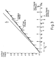
- the associated phase trajectories are illustrated in Fig. 2. It can then be seen that he resulting phase errors are a function of the slow NCO frequency and the time between phase corrections compared to the fast divider clock.
- the technique may be used to generate a square wave clock by using some simplifications.
- the fast phase ramp may be generated by dividing the sample clock by 2. Alternate output samples of 0 or ** will thus result. This represents a phase ramp of half the sample frequency. The ramp must therefore be slowed by subtracting an NCO phase ramp output.
- the required output clock waveform may be obtained by truncating the phase sum to 1 bit and inverting.
- the addition may be performed simply by modulo two addition of the fast phase ramp to the most significant bit (MSB) of the output of the slow NCO.
- MSB most significant bit
- the resulting circuit is an exclusive OR gate followed by an inverter.
- the fast phase ramp may be generated by a D-type bistable connected to toggle.
- Fig. 4 A possible circuit is shown in Fig. 4.
- the fast sample clock is fed to the D-type bistable 50 connected to function as a divide-by-two toggle.
- the fast clock is also fed to a divider 51 to produce a slow reference clock for the NCO 52.
- the output of bistable 50 is sumed with the most significant bit (MSB) of the NCO output in exclusive-OR gate 53 which is followed by inverter 54.
- MSB most significant bit
- the NCO is supplied with negative frequency input data. It must also be noted that the output would in practice need to be reclocked to remove glitches.
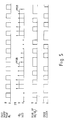
- the resultant waveforms are shown in Fig. 5. It can be seen that the clock is delayed by one sample each time the NCO phase passes n **.
Landscapes
- Engineering & Computer Science (AREA)
- Theoretical Computer Science (AREA)
- Physics & Mathematics (AREA)
- General Physics & Mathematics (AREA)
- General Engineering & Computer Science (AREA)
- Computing Systems (AREA)
- Mathematical Optimization (AREA)
- Mathematical Physics (AREA)
- Pure & Applied Mathematics (AREA)
- Mathematical Analysis (AREA)
- Computational Mathematics (AREA)
- Manipulation Of Pulses (AREA)
- Analogue/Digital Conversion (AREA)
Applications Claiming Priority (2)
| Application Number | Priority Date | Filing Date | Title |
|---|---|---|---|
| GB8723856A GB2211039B (en) | 1987-10-10 | 1987-10-10 | Digital frequency converter |
| GB8723856 | 1987-10-10 |
Publications (2)
| Publication Number | Publication Date |
|---|---|
| EP0312192A2 true EP0312192A2 (de) | 1989-04-19 |
| EP0312192A3 EP0312192A3 (de) | 1991-04-03 |
Family
ID=10625140
Family Applications (1)
| Application Number | Title | Priority Date | Filing Date |
|---|---|---|---|
| EP19880306671 Withdrawn EP0312192A3 (de) | 1987-10-10 | 1988-07-20 | Digitaler Frequenzwandler |
Country Status (4)
| Country | Link |
|---|---|
| US (1) | US4914397A (de) |
| EP (1) | EP0312192A3 (de) |
| JP (1) | JPH01103304A (de) |
| GB (1) | GB2211039B (de) |
Cited By (1)
| Publication number | Priority date | Publication date | Assignee | Title |
|---|---|---|---|---|
| EP0798856A1 (de) * | 1996-03-29 | 1997-10-01 | STMicroelectronics S.A. | Impulsgeneratorschaltung |
Families Citing this family (3)
| Publication number | Priority date | Publication date | Assignee | Title |
|---|---|---|---|---|
| JP2545008B2 (ja) * | 1991-11-21 | 1996-10-16 | ソニー・テクトロニクス株式会社 | 可変周波数信号発生方法 |
| US5365182A (en) * | 1993-06-22 | 1994-11-15 | Motorola, Inc. | Method and apparatus for low power clock generation for high speed applications |
| US8447007B2 (en) * | 2011-07-11 | 2013-05-21 | Qualcomm Incorporated | Multi-clock real-time counter |
Family Cites Families (8)
| Publication number | Priority date | Publication date | Assignee | Title |
|---|---|---|---|---|
| US4185247A (en) * | 1978-01-03 | 1980-01-22 | The United States Of America As Represented By The Secretary Of The Air Force | Means for reducing spurious frequencies in a direct frequency synthesizer |
| CA1124338A (en) * | 1980-03-21 | 1982-05-25 | James K. Reichert | Variable phase lock control |
| US4365203A (en) * | 1981-02-05 | 1982-12-21 | General Electric Company | Multi-frequency clock generator with error-free frequency switching |
| FR2511564A1 (fr) * | 1981-08-17 | 1983-02-18 | Thomson Csf | Synthetiseur de frequences a division fractionnaire, utilise pour une modulation angulaire numerique |
| US4484296A (en) * | 1982-07-19 | 1984-11-20 | Rockwell International Corporation | Phase programmable signal generator means |
| US4636734A (en) * | 1983-07-05 | 1987-01-13 | Motorola, Inc. | Low spurious numerically controlled oscillator apparatus and method |
| JPS61186023A (ja) * | 1985-02-13 | 1986-08-19 | Sharp Corp | クロック発生回路 |
| AU593671B2 (en) * | 1986-08-12 | 1990-02-15 | Alcatel N.V. | Signal generator |
-
1987
- 1987-10-10 GB GB8723856A patent/GB2211039B/en not_active Expired - Fee Related
-
1988
- 1988-07-20 EP EP19880306671 patent/EP0312192A3/de not_active Withdrawn
- 1988-08-01 US US07/227,017 patent/US4914397A/en not_active Expired - Fee Related
- 1988-08-30 JP JP63216201A patent/JPH01103304A/ja active Pending
Cited By (3)
| Publication number | Priority date | Publication date | Assignee | Title |
|---|---|---|---|---|
| EP0798856A1 (de) * | 1996-03-29 | 1997-10-01 | STMicroelectronics S.A. | Impulsgeneratorschaltung |
| FR2746986A1 (fr) * | 1996-03-29 | 1997-10-03 | Sgs Thomson Microelectronics | Circuit de production d'impulsions |
| US5886555A (en) * | 1996-03-29 | 1999-03-23 | Sgs-Thomson Microelectronics S.A. | Pulse production circuit |
Also Published As
| Publication number | Publication date |
|---|---|
| GB2211039B (en) | 1991-10-23 |
| US4914397A (en) | 1990-04-03 |
| EP0312192A3 (de) | 1991-04-03 |
| GB2211039A (en) | 1989-06-21 |
| JPH01103304A (ja) | 1989-04-20 |
| GB8723856D0 (en) | 1987-11-11 |
Similar Documents
| Publication | Publication Date | Title |
|---|---|---|
| EP0338742B1 (de) | Direkter digitaler Synthetisierer mit Akkumulator und wählbarem Zufallsgenerator | |
| US3772681A (en) | Frequency synthesiser | |
| US4066978A (en) | Digital phase-locked loop filter | |
| EP0102784A2 (de) | Verfahren und Anordnung zum Erzeugen einer Sinusfunktion | |
| EP1469373A1 (de) | Direkter digitaler Frequenzsynthetisierer für ein zellulares schnurloses Kommunikationssystem basierend auf schneller Frequenzsprung-Spreizspektrum-Technologie | |
| EP0419680B1 (de) | Frequenzmodulator | |
| RU94042898A (ru) | Демодулятор методом фазовой манипуляции | |
| US5673212A (en) | Method and apparatus for numerically controlled oscillator with partitioned phase accumulator | |
| US4868428A (en) | Apparatus for shifting the frequency of complex signals | |
| JPS61234624A (ja) | 可聴信号をプログラマブルに移相するディジタル装置と方法 | |
| US7188131B2 (en) | Random number generator | |
| US4543542A (en) | Phase locked loop frequency and phase modulators | |
| EP0312192A2 (de) | Digitaler Frequenzwandler | |
| JPS6247379B2 (de) | ||
| US4910695A (en) | Code correlation arrangement | |
| EP0507511B1 (de) | Digitaler Phase/Frequenzwandler für VHF-Phasenregelschleifen | |
| US5424664A (en) | Direct digital synthesizer with adjustable clock frequency | |
| US4559613A (en) | Digital frequency synthesizer circuit | |
| Noel et al. | Frequency synthesis: A comparison of techniques | |
| EP0125811B1 (de) | Frequenzgenerator | |
| US6317457B1 (en) | Pulse density modulator | |
| US4210776A (en) | Linear digital phase lock loop | |
| GB1575629A (en) | Generator for generating sinusoidal electrical signals which are phase or frequency modulated by a digital method | |
| US5124958A (en) | Digital Tau synthesizer | |
| GB2217127A (en) | Direct frequency synthesiser |
Legal Events
| Date | Code | Title | Description |
|---|---|---|---|
| PUAI | Public reference made under article 153(3) epc to a published international application that has entered the european phase |
Free format text: ORIGINAL CODE: 0009012 |
|
| AK | Designated contracting states |
Kind code of ref document: A2 Designated state(s): DE ES FR IT |
|
| PUAL | Search report despatched |
Free format text: ORIGINAL CODE: 0009013 |
|
| AK | Designated contracting states |
Kind code of ref document: A3 Designated state(s): DE ES FR IT |
|
| 17P | Request for examination filed |
Effective date: 19910314 |
|
| 17Q | First examination report despatched |
Effective date: 19931013 |
|
| RAP1 | Party data changed (applicant data changed or rights of an application transferred) |
Owner name: NORTHERN TELECOM LIMITED |
|
| STAA | Information on the status of an ep patent application or granted ep patent |
Free format text: STATUS: THE APPLICATION IS DEEMED TO BE WITHDRAWN |
|
| 18D | Application deemed to be withdrawn |
Effective date: 19950930 |