EP0312240A2 - Pièce de connexion électrique femelle - Google Patents
Pièce de connexion électrique femelle Download PDFInfo
- Publication number
- EP0312240A2 EP0312240A2 EP88309256A EP88309256A EP0312240A2 EP 0312240 A2 EP0312240 A2 EP 0312240A2 EP 88309256 A EP88309256 A EP 88309256A EP 88309256 A EP88309256 A EP 88309256A EP 0312240 A2 EP0312240 A2 EP 0312240A2
- Authority
- EP
- European Patent Office
- Prior art keywords
- piece
- contact piece
- mutually opposing
- connector piece
- connector
- Prior art date
- Legal status (The legal status is an assumption and is not a legal conclusion. Google has not performed a legal analysis and makes no representation as to the accuracy of the status listed.)
- Withdrawn
Links
Images


Classifications
-
- H—ELECTRICITY
- H01—ELECTRIC ELEMENTS
- H01R—ELECTRICALLY-CONDUCTIVE CONNECTIONS; STRUCTURAL ASSOCIATIONS OF A PLURALITY OF MUTUALLY-INSULATED ELECTRICAL CONNECTING ELEMENTS; COUPLING DEVICES; CURRENT COLLECTORS
- H01R13/00—Details of coupling devices of the kinds covered by groups H01R12/70 or H01R24/00 - H01R33/00
- H01R13/02—Contact members
- H01R13/15—Pins, blades or sockets having separate spring member for producing or increasing contact pressure
- H01R13/187—Pins, blades or sockets having separate spring member for producing or increasing contact pressure with spring member in the socket
Definitions
- the present invention relates to an improved electric connector piece for a female connector which is adapted to receive a pin-shaped male connector piece to achieve an electric connection therewith.
- the electric connector pieces are typically each formed into an elongated box.
- an electroconductive plate is bent into an electric connector piece 101 shaped as an elongated box provided with a lead terminal piece 101 at one of its longitudinal ends, and a pair of projecting tabs 103 and 104 formed in the mutually opposing strips 101a and 101b of the connector piece 101 in such a manner that one of the tabs 103 serves as a contact piece while the other tab 104 serves as a spring piece which elastically urges an electric male connector piece not shown in the drawing against the contact piece.
- the contact piece 103 is integrally formed with the elongated, box-shaped electric connector piece 101, the whole electric connector piece 101 must be gold plated even though only the contact piece 103 is required to be gold plated, and the unnecessary gold plating leads to the increase in material cost.
- the connector piece 101 is constructed from a connector piece main body 105 having a C-shaped cross section, and a planar sheet spring piece 106. Securing tabs 107 provided in each upper edge of a pair of mutually opposing strips 105a and 105b of the connector piece main body 105 are crimped against the spring piece 106, and a contact tab 108 is bent from the connecting strip 105c of the connector piece main body 105.
- the contact tab 108 is integrally formed with the connector piece main body 105, the whole connector piece main body 105 having the C-shaped cross section must be gold plated, and the material cost tends to be high. Furthermore, crimping the securing tabs 107 against the spring piece 106 tends to reduce the manufacturing work efficiency.
- a primary object of the present invention is to provide an electric connector piece for a female connector which can reduce the manufacturing cost through the reduction of the cost for gold plating.
- a second object of the present invention is to provide an electric connector piece for a female connector which offers an improved efficiency for its manufacture.
- a third object of the present invention is to provide an electric connector piece for a female connector which offers a favorable tolerance to the deviation from exact alignment with the corresponding male connector piece so that the female connector may be favorably used in multiple connectors.
- an electric female connector piece for receiving a pin-shaped male connector piece therein for achieving an electric connection therewith, comprising: a connector piece main body having a C-shaped cross section by being provided with a pair of mutually opposing, elongated strips which are joined together at their long sides by a connecting strip; a contact piece consisting of an elongated strip which is adapted to be disposed between the mutually opposing strips defining a cavity of a substantially rectangular cross section; a fitting hole provided in a middle part of each of the mutually opposing strips for receiving a fitting projection provided in each lateral long edge of the contact piece; a first engagement portion provided in each of the mutually opposing strips at its lengthwise end for engagement with a corresponding part of the contact piece; a second engagement portion provided in each of the mutually opposing strips at its other lengthwise end for engagement with another corresponding part of the contact piece; and a spring tab bent from the the connecting strip for elastically urging the male connector piece against the contact
- the connector piece main body having a C-shaped cross section and the elongated contact piece mounted thereto are made from two separate pieces, gold plating may be performed only to the contact piece and the manufacturing cost can be thereby reduced.
- the contact piece can be mounted to the connector piece simply by fitting and engaging them together, the work efficiency of the manufacturing process can be improved, in particular when at least one of the engagement portions comprises a step-shaped notch provided in each of the mutually opposing strips, and a lateral engagement projection provided in each lateral edge of the contact piece for defining a corresponding notch adapted to engage the step-shaped notch.
- the contact piece is bent about a lateral line passing through the fitting projections with its convex surface facing the connecting strip, and the state of favorable contact between the contact piece and the corresponding male connector piece can be accomplished in addition to the obvious advantage of providing a converging taper suitable for receiving the male connector piece into the cavity of the female connector piece.
- the contact piece is given with a certain freedom of movement. Thereby, some tolerance is produced in the alignment between the pin-shaped male connector piece and the female connector piece. This is particularly significant when this connector piece is applied to a multiple connector. Further, this freedom of movement is advantageous also in achieving a favorable contact state with the male connector piece in cooperation with the spring tab.
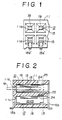
- Figures 1 and 2 are a front view and a side sectional view of an example of multiple connector which incorporates the electric connector pieces for a female connector according to the present invention.
- This multiple female connector comprises a connector casing 11 made of an electrically insulating synthetic resin material which is provided with a plurality of insertion openings 11a each for inserting a pin-shaped electric connector piece M of a male connector therefrom, in two rows one above the other. Each of the insertion openings 11a communicates, in mutual alignment, with a receiving hole 13 for receiving the electric connector piece 12 for this female connector according to the present invention.
- This electric connector piece 12 consists of a connector piece main body 14, and an elongated contact piece 15 which is mounted to the main body 14, and these two parts jointly defines the elongated box-shape of this connector piece 12.
- the connector piece main body 14 is made of stainless steel, and has a C-shaped cross section by being provided with a pair of mutually opposing, elongated strips 14a and 14b which are joined together at their long sides by a connecting strip 14c.
- the lengthwise middle parts of the mutually opposing strips 14a and 14b are provided with rectangular fitting holes 16 and 16, respectively.
- the front ends of the mutually opposing strips 14a and 14b are provided with first steps 17 and 17, respectively, and the rear ends of the mutually opposing strips 14a and 14b are likewise provided with second steps 18 and 18, respectively.
- a spring tab 19 is bent obliquely from the front end of the connecting strip 14c towards the rear as shown in Figure 5 so that the male electric connector piece M ( Figure 2) may be smoothly admitted into the rectangular cavity defined by the connector piece main body 14 and the contact piece 15 may be elastically urged against the contact piece 15 as the male electric connector piece M is inserted into the cavity.
- the main part 15a of the contact piece 15 is provided with lateral projections 20 and 20 so as to correspond to the fitting holes 16 and 16, respectively, Further, the front end of the contact piece 15 is provided with similar lateral projections 21 and 21 which define first notches 21a and 21a adapted to engage with the corresponding first steps 17 and 17, respectively, of the connector piece main body 14 while the portions of the contact piece 15 situated to the rear of the projections 20 and 20 are provided with similar lateral projections 22 and 22 which likewise define second notches 22a and 22a adapted to engage with the second steps 18 and 18, respectively.
- the portion of the main part 15a of the contact piece 15 located between the first notches 21 and the second notches 22 is bent into a V-shape about a lateral line passing through the projections 20, while the rear end of the contact piece 15 is provided with an extension 15b constructed as a lead terminal piece and adapted to be bent into a prescribed configuration as illustrated in the upper part of Figure 2.
- the extension 15b may be provided to the front end projections 21, instead of the rear end projections 22, as illustrated in the lower parts of Figures 1 and 2 and denoted with numeral 15b′, to avoid the interference with the extension of the contact piece arranged above it or to provide a better convenience of mounting the multiple female connector, to which this contact piece is applied, to a printed circuit board or the like.
- Numeral 23 denotes an engagement tab which is bent from the rear end of the connecting strip 14c of the connector piece main body 14 for engagement with a depression or a hole 24 ( Figure 2) formed in the connector casing 11.
- the elongated, box-shaped electric connector piece 12 is formed by fitting the projections 20 and 20 of the contact piece 15 into the fitting holes 16 and 16 of the connector piece main body 14, engaging the first notches 21a and 21a of the contact piece 15 with the first steps 17 and 17 of the connector piece main body 14, and engaging the second notches 22a and 22a with the second steps 18 and 18, for mounting the contact piece 15 into the connector piece main body 14.
- this electric connector piece 12 is inserted into the receiving hole 13 from the rear end of the connector casing 11, the engagement piece 23 is caught by the engagement depression or teh engagement hole 24, and the electric connector piece 12 is securely held in the connector casing 11.
- the electric connector piece M of the male connector inserted from the insertion opening 11a comes into contact with the contact piece 15 under the elastic force of the spring piece 19.
- the electric connector piece 12 consists of two pieces, or the C-shaped connector piece main body 14 and the elongated contact piece 15 assembled thereto, gold plating may be performed only to the contact piece 15 and the waste of material can be thereby avoided. Furthermore, since the contact piece 15 is held between the mutually opposing strips 14a and 14b of the connector piece main body 14, the width w2 may be made substantially smaller than the width w1 of the connector piece main body 14, and the manufacturing cost can be reduced by reducing the amount of gold plating.
- the contact piece 15 is mounted to the connector piece main body 14 by way of the fitting portions 16 (20) of the two parts 14 and 15, and the first and the second engagement portions 17 (21a) and 18 (22a), the assembly work is simplified as compared to the case which involves a crimping process. And, since the stress due to the inserting force of the electric connector piece M of the male connector can be absorbed by the fitting portions 16 (20) of the two parts, a favorable contact state can be maintained even in the case of multiple connectors even in the presence of dimensional errors in the corresponding male connector pins and/or the casing of the female connector.
Landscapes
- Connector Housings Or Holding Contact Members (AREA)
- Details Of Connecting Devices For Male And Female Coupling (AREA)
Applications Claiming Priority (2)
| Application Number | Priority Date | Filing Date | Title |
|---|---|---|---|
| JP156592/87 | 1987-10-13 | ||
| JP1987156592U JPH0162671U (fr) | 1987-10-13 | 1987-10-13 |
Publications (2)
| Publication Number | Publication Date |
|---|---|
| EP0312240A2 true EP0312240A2 (fr) | 1989-04-19 |
| EP0312240A3 EP0312240A3 (fr) | 1990-04-18 |
Family
ID=15631129
Family Applications (1)
| Application Number | Title | Priority Date | Filing Date |
|---|---|---|---|
| EP88309256A Withdrawn EP0312240A3 (fr) | 1987-10-13 | 1988-10-05 | Pièce de connexion électrique femelle |
Country Status (3)
| Country | Link |
|---|---|
| US (1) | US4880401A (fr) |
| EP (1) | EP0312240A3 (fr) |
| JP (1) | JPH0162671U (fr) |
Cited By (1)
| Publication number | Priority date | Publication date | Assignee | Title |
|---|---|---|---|---|
| EP0651464A3 (fr) * | 1993-10-27 | 1996-11-13 | Whitaker Corp | Raccord par déplacement d'isolation avec ressort de renforcement. |
Families Citing this family (25)
| Publication number | Priority date | Publication date | Assignee | Title |
|---|---|---|---|---|
| US5271741A (en) * | 1990-02-21 | 1993-12-21 | Yazaki Corporation | Female socket contact |
| JPH0633659Y2 (ja) * | 1990-02-21 | 1994-08-31 | 矢崎総業株式会社 | 雌型端子金具 |
| JPH0494275U (fr) * | 1991-01-11 | 1992-08-17 | ||
| GB9124572D0 (en) * | 1991-11-20 | 1992-01-08 | Amp Gmbh | Electrical terminal having improved retention means |
| US5217382A (en) * | 1992-06-05 | 1993-06-08 | Interlock Corporation | Electric receptacle with shape memory spring member |
| JPH0750178A (ja) * | 1993-08-03 | 1995-02-21 | Yazaki Corp | 電気接続子とその製造方法 |
| US6062918A (en) * | 1996-07-01 | 2000-05-16 | The Whitaker Corporation | Electrical receptacle contact assembly |
| JP3494850B2 (ja) * | 1997-06-12 | 2004-02-09 | 矢崎総業株式会社 | コネクタ用端子 |
| US6024612A (en) * | 1997-09-23 | 2000-02-15 | The Whitaker Corporation | Receptacle contact |
| JP3529026B2 (ja) * | 1998-04-15 | 2004-05-24 | 矢崎総業株式会社 | 雌端子 |
| US7241190B2 (en) * | 2001-11-20 | 2007-07-10 | Fci Americas Technology, Inc. | Female electrical terminal and electrical connector comprising the same |
| FR2840736B1 (fr) * | 2002-06-11 | 2004-08-27 | Framatome Connectors Int | Borne de contact electrique femelle d'une seule piece ayant une partie de transition renforcee |
| DE10331034B8 (de) * | 2002-08-21 | 2015-04-16 | Tyco Electronics Amp Gmbh | Kontaktbuchse |
| FR2850488B1 (fr) * | 2003-01-24 | 2006-02-10 | Dgtec | Module photovoltaique comportant des bornes de connexion avec l'exterieur |
| JP4297825B2 (ja) * | 2003-11-04 | 2009-07-15 | モレックス インコーポレイテド | ケーブルコネクタ |
| JP2005183160A (ja) * | 2003-12-19 | 2005-07-07 | Jst Mfg Co Ltd | 雌コンタクト |
| US7537497B2 (en) * | 2005-09-26 | 2009-05-26 | Fci Americas Technology, Inc. | Multi-piece electrical receptacle terminal |
| US7976353B2 (en) * | 2006-09-29 | 2011-07-12 | Tyco Electronics Corporation | Two-piece electrical terminal |
| US7294027B1 (en) | 2006-10-03 | 2007-11-13 | Fci Americas Technology, Inc. | Electrical terminal with layered springs |
| US7556541B2 (en) * | 2006-10-06 | 2009-07-07 | Fci Americas Technology, Inc. | Electrical terminal with high conductivity core |
| JP2008140589A (ja) * | 2006-11-30 | 2008-06-19 | Yazaki Corp | 雌型端子 |
| US8167640B2 (en) * | 2009-03-19 | 2012-05-01 | Bioness Inc. | Flexible connector for implantable electrical stimulation lead |
| CN105940568B (zh) * | 2014-01-31 | 2019-05-03 | 松下知识产权经营株式会社 | 连接器和连接器装置 |
| JP5930089B1 (ja) * | 2015-02-24 | 2016-06-08 | 第一精工株式会社 | 導電端子 |
| DE102015104377B4 (de) * | 2015-03-24 | 2020-04-02 | Lisa Dräxlmaier GmbH | Kontaktteil und Verfahren zum Herstellen eines Kontaktteils |
Family Cites Families (9)
| Publication number | Priority date | Publication date | Assignee | Title |
|---|---|---|---|---|
| US2775746A (en) * | 1954-01-19 | 1956-12-25 | Young Sidney Geoffrey | Electrical socket connectors |
| GB1061181A (en) * | 1963-04-04 | 1967-03-08 | Anthony Bikker | Improvements relating to electrical connectors |
| US3370265A (en) * | 1966-05-09 | 1968-02-20 | Berg Electronics Inc | Electrical connector |
| US3796987A (en) * | 1972-06-09 | 1974-03-12 | Amp Inc | Electrical receptacle and connector |
| JPS535793A (en) * | 1976-07-06 | 1978-01-19 | Matsushita Electric Works Ltd | Edg e receiving spring of plug receptacle |
| JPS6046796B2 (ja) * | 1977-08-19 | 1985-10-17 | ソニー株式会社 | 高周波誘導加熱装置の発振制御装置 |
| CA1122292A (fr) * | 1979-03-26 | 1982-04-20 | George A. Patton | Douille d'electricite |
| US4342498A (en) * | 1979-03-26 | 1982-08-03 | Akzona Incorporated | Electrical socket |
| JPS6091573A (ja) * | 1983-10-26 | 1985-05-22 | 矢崎総業株式会社 | 自動車用ワイヤ−ハ−ネス |
-
1987
- 1987-10-13 JP JP1987156592U patent/JPH0162671U/ja active Pending
-
1988
- 1988-09-27 US US07/250,264 patent/US4880401A/en not_active Expired - Fee Related
- 1988-10-05 EP EP88309256A patent/EP0312240A3/fr not_active Withdrawn
Cited By (1)
| Publication number | Priority date | Publication date | Assignee | Title |
|---|---|---|---|---|
| EP0651464A3 (fr) * | 1993-10-27 | 1996-11-13 | Whitaker Corp | Raccord par déplacement d'isolation avec ressort de renforcement. |
Also Published As
| Publication number | Publication date |
|---|---|
| US4880401A (en) | 1989-11-14 |
| EP0312240A3 (fr) | 1990-04-18 |
| JPH0162671U (fr) | 1989-04-21 |
Similar Documents
| Publication | Publication Date | Title |
|---|---|---|
| US4880401A (en) | Electric female connector piece | |
| US5692928A (en) | Electrical connector having terminals with improved retention means | |
| US5297966A (en) | Mounting bracket for an electrical connector | |
| US4699444A (en) | Electrical receptacle which assures positive connection | |
| US5584709A (en) | Printed circuit board mounted electrical connector | |
| US4655518A (en) | Backplane connector | |
| US4647136A (en) | Modular plug and printed circuit connector | |
| US7052320B2 (en) | Electrical connector having shielding plates | |
| US5490787A (en) | Electrical connector with integral supporting structure | |
| US4597625A (en) | Electrical connector | |
| US5306182A (en) | Electric connector terminal | |
| EP0815621B1 (fr) | Ensemble prise electrique et son contact a ressort | |
| CA1265221A (fr) | Borne de connexion electrique pour connecteur | |
| US5575663A (en) | Electrical connector for mounting to an edge of a circuit board | |
| US6371811B1 (en) | Vertical-type universal serial bus connector having a low profile on a printed circuit board | |
| US4752246A (en) | Preloaded spring contact electrical terminal | |
| JPS6142887A (ja) | 電気コネクタ | |
| US4634200A (en) | Low profile stacking connector for printed circuit boards | |
| US4859198A (en) | Contact assembly | |
| US4909762A (en) | Electric connector | |
| HK140494A (en) | Electric connector | |
| EP0601703B1 (fr) | Support pour le montage d'un connecteur électrique | |
| US20060141839A1 (en) | Electrical card connector | |
| US6979237B2 (en) | Electrical connector having receptacle contacts | |
| EP0981103A1 (fr) | Connecteur pour cartes à puce ayant différentes épaisseurs |
Legal Events
| Date | Code | Title | Description |
|---|---|---|---|
| PUAI | Public reference made under article 153(3) epc to a published international application that has entered the european phase |
Free format text: ORIGINAL CODE: 0009012 |
|
| 17P | Request for examination filed |
Effective date: 19881123 |
|
| AK | Designated contracting states |
Kind code of ref document: A2 Designated state(s): AT BE CH DE ES FR GB GR IT LI LU NL SE |
|
| PUAL | Search report despatched |
Free format text: ORIGINAL CODE: 0009013 |
|
| AK | Designated contracting states |
Kind code of ref document: A3 Designated state(s): AT BE CH DE ES FR GB GR IT LI LU NL SE |
|
| RAP1 | Party data changed (applicant data changed or rights of an application transferred) |
Owner name: OMRON CORPORATION |
|
| 17Q | First examination report despatched |
Effective date: 19920610 |
|
| STAA | Information on the status of an ep patent application or granted ep patent |
Free format text: STATUS: THE APPLICATION IS DEEMED TO BE WITHDRAWN |
|
| 18D | Application deemed to be withdrawn |
Effective date: 19921021 |
|
| ITF | It: translation for a ep patent filed |