EP0312247A2 - Méthode et appareil pour la qualification des équipements d'une centrale nucléaire - Google Patents
Méthode et appareil pour la qualification des équipements d'une centrale nucléaire Download PDFInfo
- Publication number
- EP0312247A2 EP0312247A2 EP88309280A EP88309280A EP0312247A2 EP 0312247 A2 EP0312247 A2 EP 0312247A2 EP 88309280 A EP88309280 A EP 88309280A EP 88309280 A EP88309280 A EP 88309280A EP 0312247 A2 EP0312247 A2 EP 0312247A2
- Authority
- EP
- European Patent Office
- Prior art keywords
- object piece
- radiation
- dosimetry
- exposure
- temperature
- Prior art date
- Legal status (The legal status is an assumption and is not a legal conclusion. Google has not performed a legal analysis and makes no representation as to the accuracy of the status listed.)
- Granted
Links
Images


Classifications
-
- G—PHYSICS
- G21—NUCLEAR PHYSICS; NUCLEAR ENGINEERING
- G21C—NUCLEAR REACTORS
- G21C17/00—Monitoring; Testing ; Maintaining
-
- Y—GENERAL TAGGING OF NEW TECHNOLOGICAL DEVELOPMENTS; GENERAL TAGGING OF CROSS-SECTIONAL TECHNOLOGIES SPANNING OVER SEVERAL SECTIONS OF THE IPC; TECHNICAL SUBJECTS COVERED BY FORMER USPC CROSS-REFERENCE ART COLLECTIONS [XRACs] AND DIGESTS
- Y02—TECHNOLOGIES OR APPLICATIONS FOR MITIGATION OR ADAPTATION AGAINST CLIMATE CHANGE
- Y02E—REDUCTION OF GREENHOUSE GAS [GHG] EMISSIONS, RELATED TO ENERGY GENERATION, TRANSMISSION OR DISTRIBUTION
- Y02E30/00—Energy generation of nuclear origin
- Y02E30/30—Nuclear fission reactors
Definitions
- This invention relates generally to nuclear power generating stations, and more particularly to a method and apparatus for the generation and maintenance of evidence to assure that qualified equipment used in such stations will operate on demand, to meet the system performance requirements.
- Safety system equipment in nuclear power generating stations is required to be capable of performing satisfactorily under defined conditions, including postulated design basis events such as a loss of coolant accident. It is necessary to provide assurance that such equipment meets its performance requirement throughout its installed life. This is accomplished through a disciplined program of design, qualification, production quality control, installation, maintenance, and surveillance testing.
- the process of qualification usually also establishes the qualified lifetime of the equipment. That is the period of time, prior to the start of a design basis event, for which the equipment is demonstrated to meet the design requirements for the specified service conditions. At the end of qualified lifetime, such equipment should be capable of performing the safety functions required for the postulated design basis, and post-design basis events.
- the qualified or safe lifetime of equipment may be allowed to be extended if it can be shown that the service or environment conditions originally assumed were overly conservative with respect to the conditions that apply at the equipment's real installed location. Use of extension methods requires documentation of the program to be followed and auditable records of the results, as illustrated in the IEEE Std 323-1974, "IEEE Standard for Qualifying Class IE Equipment for Nuclear Power Generating Stations", which is incorporated herein by reference.
- the total radiation dose to which the equipment is exposed in qualification-testing depends upon the expected normal radiation environment and the length of time following an accident that the equipment is required to operate.
- Nuclear power plant personnel will require a knowledge of the total integrated radiation dose that a piece of equipment has received if it is desired to extend the equipment qualification beyond the present qualified life, or if it is desired to requalify equipment following an accident.
- the radiation doses used for equipment qualification are sufficiently conservative that, if the actual integrated doses are known, the equipment could continue in service without exceeding the existing qualification envelopes. This is particularly true for an accident where the distribution of radiation levels in the nuclear power plant will vary widely, and be much lower than that assumed for qualification, due to radioactive decay during the release, the physical distribution of radioactive material, and the presence of local shielding in the form of structure, other equipment, floors, and walls.
- nuclear power plant personnel would have very few options with regard to thermal and radiation aging of important equipment. Qualified equipment could be replaced when it reached the end of its qualified lifetime in calendar years without regard to the actual environmental aging; or, nuclear power plant life extension decisions and decisions regarding qualified equipment could be made based upon a projection of very limited active-temperature and radiation level measurements. Without measured data, the affected equipment could either be replaced, refurbished, or disassembled, inspected, and reassembled. Major problems with such approaches, however, exist in the time and cost for replacement or refurbishment, as well as considerations affecting qualified equipment vendors and qualified repair parts. Therefore, what is needed is a passive system that provides integrated radiation dose and thermal history throughout normal plant operation, through the duration of a nuclear power plant accident, and beyond.
- the present invention also provides (i) data to support continued use of qualified equipment following an accident, (ii) data to support nuclear power plant life/license extension applications, (iii) data to support an observation that an object piece of qualified equipment has not yet reached the end of its qualified life.
- the present invention demonstrates utility management prudence with regard to an integrated equipment surveillance program, pre-planning for nuclear power plant lifetime/license extension (PLEX), and a commitment to post-accident nuclear power plant recovery.
- PLEX nuclear power plant lifetime/license extension
- the invention resides in an apparatus for monitoring degradation of the life of an object piece of equipment in a nuclear power plant owing to radiation and service aging of the object piece, without removing the object piece from service, said apparatus characterized by passive means for detecting a total integrated dose of radiation received by the object piece; means for projecting a thermal history of the object piece; and means for housing said passive detection means and said projection means in close proximity to the object piece.
- the passive detection means includes first dosimetry means for measuring a gamma ray dose, and second dosimetry means for measuring a beta ray dose.
- the projection means includes first monitor means for determining a peak temperature experienced by the object piece, and second monitor means for determining an integrated thermal exposure to the object piece.
- a method of monitoring the object piece which utilizes apparatus in accordance with the first embodiment includes the steps of mounting such passive detection means and projection means in close proximity to the object piece, exposing such mounted means to the environment in a normally operating nuclear power plant, and periodically analyzing the first and second dosimetry means and first and second monitor means to determine whether the qualified life of the object piece may be extended.
- the passive detection means and projection means are accomplished through a miniature or representative sample of the object piece, preaged to a number of years, which can be tested periodically for those properties important to the survival of the object piece with respect to its age.
- Such miniaturized or representative sample of the object piece is preaged through exposure to a controlled dose of radiation corresponding to the normal radiation experienced in a nuclear power plant over a predetermined period of time and the radiation experienced during a preselected accident.
- Such preaging also includes exposure of the miniaturized or representative sample to a thermal profile corresponding to a predetermined service temperature.
- a method of monitoring the object piece includes the performance of baseline tests prior to the installation of the miniaturized or representative sample in the nuclear power plant, exposing the sample to the environment of the normally operating nuclear power plant, and periodically repeating the baseline tests to determine whether the qualified life of the object piece may be extended by comparing that qualified life to the installed life plus the number of years corresponding to the preaged life of the sample.
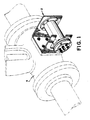
- Fig. 1 a first embodiment of a monitor 2 attached to the side of a motor-operated valve 4, such as an in-containment gate valve of a nuclear power plant.
- the valve 4 may be considered for purposes of the present application to be safety-related, and conventionally includes a motor operator (not shown) which is qualified in accordance with WCAP-8587, Revision 6-A (NP), entitled "Methodology for Qualifying Westinghouse WRD Supplied NSSS Safety-Related Electrical Equipment", approved by the U.S.
- the monitor 2 may alternatively be mounted to the motor operator (not shown) instead of the valve so long as the monitor 2 is in close proximity to the object piece of qualified equipment, which is in this case the valve 4.
- the monitor 2 is generally comprised of first dosimetry means 6 for measuring a gamma ray dose and second dosimetry means 8 for measuring a beta ray dose, the first and second dosimetry means 6,8 together comprise a passive means 10 for detecting a total integrated dose of radiation received by the object piece or valve 4.
- the first dosimetry means 6 includes color-center formation means 12 for measuring the gamma ray dose in a range of from approximately 103 rads to 1010 rads, thermoluminescent dosimetry means 14 for measuring the gamma ray dose in a range of from 10 rads to approximately 105 rads, and means 16 for holding the color-center formation means 12 and the thermoluminescent dosimetry means 14 within a holder body 18 including an end plate portion 20, a tubular portion 22, and a flange portion 24.
- the end plate portion 20 includes a plurality of through holes 26 and tapped holes 28 through which the holder body 18 may be attached to a support stand 30.
- the support stand 30 is also configured so as to be adapted for mounting directly to an object piece of equipment, such as is shown in Fig. 1, or stand freely in close proximity to the object piece.
- the color-center formation means 12 comprises in a presently preferred embodiment a plurality of conventional lithium fluoride (LiF) optical crystals 32.
- ionizing radiation produces relatively stable color-centers in lithium fluoride.
- the values of the optical absorbance of the maxima of the resulting absorption bands are measured at a plurality of discrete wavelengths.
- the principle of color-center formation as a radiation dosimeter involves exposure to ionizing radiation which results in trapped electrons in negative ion vacancies in the lattice. These trapped electrons are responsible for the optical absorbance phenomenon known as "color-centers".
- Each of the LiF optical crystals is read by measuring the amount of optical absorbance at wavelengths which correspond to the various color-centers of interest. This measurement may be made using any commercially available UV-Vis spectrophotometer, with one suitable such spectrophotometer being made by Varian Instrument Division, Sunnyville, California as the model TMS 200. The amount of optical absorbance determined by the spectrophotometer is then compared to a calibration curve to determine the absorbed dose. It should be noted at this juncture that such reading of the LiF optical crystals 32 does not alter the color-centers themselves. Therefore, each dosimeter 12 constitutes a rereadable permanent record.
- a presently preferred form for the lithium fluoride dosimeter is as a cleaved lithium fluoride crystal, approximately 6 millimeters by 6 millimeters by 2 millimeters in size, which are commercially available from the Harshaw Chemical Company, Solon, Ohio, USA.
- a permanent identification number is enclosed on one of the 2 millimeters by 6 millimeters edges of each crystal 32 to ensure traceability.
- thermoluminescent dosimetry means 14 comprises in a presently preferred embodiment at least one conventional manganese activated calcium fluoride thermoluminescent dosimeter capable of providing gamma-ray dose information below approximately 105 rads.
- the monitor 2 preferably includes a plurality of solid state track recorders (SSTR).
- SSTRs consist of reusable deposits of fissionable material on high purity nickel backing disks in surface contact with replaceable mica.
- neutron-induced fission in isotopes of uranium, plutonium, and neptunium produces latent fission-fragment tracks in the SSTR.
- Such tracks are developed by chemical etching to a size that is observable with an optical microscope for track counting.
- Both bare and cadmium-shielded isotopes of U-235 and Pu-239 may be used, as well as cadmium-shielded U-238 and Np-239.
- the holding means 16 is generally comprised of interlocking pieces 16a and 16b formed from a polyimide resin, such as Vespel SP-1 manufactured by Dupont ®, or a polyetheretherketone thermoplastic such as Arlon 1000 ®, manufactured by Greene, Tweed Engineered Plastics, Harleysville, Pennsylvania.
- the holding means 16 also functions to establish electron equilibrium conditions which satisfy Bragg-Gray small cavity theory requirements.
- the holding means 16 comprised of the interlocking elements 16a and 16b are shown as a dove tail arrangement, any conveniently manufactured interlocking arrangement which is capable of holding the optical crystals 12 and TLD 14, which satisfies Bragg-Gray small cavity theory electron equilibrium requirements, and which provides high-temperature/high-integrated radiation dose resistance is acceptable in accordance with the teachings herein.
- the second dosimetry means 8 is also comprised of LiF optical crystals 32, preferably contained in a slot 34 of a holder cover 36.
- Mechanical and environmental protection of the crystals 32 (not shown in Fig. 2 for clarity) is provided by beta window means 38 consisting generally of a beta window retainer plate 40, a stainless steel beta window 42, and a beta window seal 44, preferably made of Dupont Kapton ® Type H polyamide film.
- the stainless steel beta window 42 and beta window seal 44 should together comprise a surface density of less than 30 milligrams per square centimeter.
- a body seal 46 preferably comprised of the aforementioned Arlon ® 1000 polyetheretherketone is inserted between the flange portion 24 and holder cover 36 to provide the necessary environmental sealing of the body cavity.
- Each of the components of the monitor 2 is conveniently assembled with socket head cap screws and lock washers (not shown), although any other suitable means of attachment may be used.
- the holder body 18 could incorporate integrally formed mounting feet in order to be placed directly upon a flat area, or some means of attachment such as stainless steel cable could be passed through the unthreaded through holes 26 in the end plate portion 20 such that the monitor 2 could be hung from the object piece of equipment.
- the shielding arrangements provided by the monitor 2 provide sufficient beta attenuation such that only the LiF optical crystals 32 contained within the slot 34 would be exposed to beta and gamma radiation.
- the optical crystals comprising the color-center formation means 12, on the other hand, would be exposed only to gamma-rays.
- the projection means 48 is typically provided by two means (1) conventional thermal monitors which irreversivelyibly turn black when the indicated peak temperature is reached, such as Omegalabel TM temperature labels manufactured by Omega Engineering, Incorporated, Stamford, Connecticut; and (2) integrating thermal monitors comprised of solid state track recorders adapted for use as integrating thermal monitors.
- conventional thermal monitors which irreversivelyibly turn black when the indicated peak temperature is reached
- Omegalabel TM temperature labels manufactured by Omega Engineering, Incorporated, Stamford, Connecticut
- integrating thermal monitors comprised of solid state track recorders adapted for use as integrating thermal monitors.
- solid state track recorders which have been exposed to a fission source contain a known number of fission fragment tracks. These tracks are damaged areas that can be chemical etched to an observable size for optical or spark counting.
- Such damaged zones are self-repairing by annealing upon exposure of the solid state track recorder to elevated temperatures.
- the rate and amount of repair is a function of the material and the duration at the elevated temperature and may be characterized by an Arrhenius function of temperature.
- One such process for measuring temperature with solid state track recorders is disclosed in U.S. Patent No. 4,167,109, issued September 11, 1979 to Gold.
- mica or quartz track detectors may be used to measure temperature by first exposing the track detector to a known number of fission fragments, placing the track detector in an unknown temperature environment for a length of time T, and measuring the track dimetral change or change in number of tracks observed.
- the loss in. tracks is a function of temperature and time of exposure. Since the temperature dependency is quite short, in general all tracks will be removed or amended within a very short time if T is greater than T0, and none will be removed if T is less than T0 - T. Only in the region between T0 - T and T0 will fairly precise definition of exposure temperature occur.
- the temperature T0 for typical track detector materials has only a few values which do not necessarily correspond to temperature in a desired measurement range for applications with the monitor 2.
- T0 in general related closely to the melting point of the track detector, use of various plastic and glass types with different melting points will provide a range of temperatures to satisfy almost any need. Once a specific type of plastic or glass is calibrated for response to temperature and annealing, the degree of accuracy of the temperature measurement averaged over time can be ascertained.
- a method of monitoring the object piece of equipment which utilizes apparatus in accordance with the monitor 2 includes the steps of mounting the above described passive detection means 10 and projection means 48 in close proximity to the object piece, exposing such mounted means to the environment of a normally operating nuclear power plant, and periodically analyzing the passive detection 10 and projection means 48 to determine whether the qualified life of the object piece may be extended.
- a typical in core thermocouple reference junction box (RJB) 50 is monitored by a miniaturized RJB maintenance and surveillance test module 52.
- the module 52 is assembled to the same baseline design as the object equipment or RJB 50. After being pre-aged thermally and with respect to radiation to typically six years beyond the object piece of equipment, a documented baseline set of test data and parameters are obtained. The module 52 is then mounted in a representative environment of the its object piece of equipment, and allowed to continue natural aging during normal plant operation. Just before the artificially determined end of qualified life of the object equipment expires, the module is removed from its mounting and the baseline tests repeated.
- the object equipment qualified life would then be justified to be extended to its natural life plus that of the module preaging.
- the module is then reinstalled for another period equal to the preaged duration at which time the baseline tests are repeated increasing the object equipment qualified end of life another period equal to that of the preaging. Such sequence is repeated until any of the baseline tests fail, at which time, the object equipment for RJB 50 is considered to have reached its end of life, thus requiring replacement.
- the passive detection means and projection means are accomplished through a miniature or representative sample of the object piece, the passive detection means comprising first mimic means 54 which is preaged through exposure to a selected amount of radiation thereby establishing a first predetermined baseline, and the projection means comprising second mimic means 56 preaged through exposure to a selected amount of heat thereby establishing a second predetermined baseline.
- the first mimic means 54 is preaged to an equivalent of six years exposure to normal radiation with an assumed dose approximating a loss of coolant accident, the total integrated dose comprising approximately 160 megarads gamma radiation.
- the second mimic means 56 is thermally aged to an equivalent of six years exposure at a service temperature of 120°F by heating the module 52 for 107 hours at approximately 117°C. Thereafter, the preaged first and second mimic means 54, 56 of the module 52 is periodically visually inspected, as its insulation resistance measured, and is subjected to a compression/load test simulative of an earthquake to predict seismic failure.
- Temperature of the module 52 is monitored daily, as well as the radiation rate within the vicinity of the RJB 50, through means such as the aforedescribed TLD 14 (not shown in Figs. 4 or 5).
- the insulation resistance readings are performed on the extension wires 58, while the compression/load test is conveniently performed through application of a (25 lb.) 11.25 kg force to the top board 62 of the module 52.
- a method of monitoring the object piece (i.e., the RJB 50) of equipment includes the performance of the previously described baseline tests prior to its installation next to the RJB 50, exposing the module 52 to the environment of the normally operating nuclear power plant, and periodically repeating the baseline tests to determine whether the qualified life of the object piece of equipment may be extended by comparing that qualified life to the installed life plus the number of years corresponding to the preaged life of the sample.
Landscapes
- Physics & Mathematics (AREA)
- Engineering & Computer Science (AREA)
- Plasma & Fusion (AREA)
- General Engineering & Computer Science (AREA)
- High Energy & Nuclear Physics (AREA)
- Measurement Of Radiation (AREA)
- Monitoring And Testing Of Nuclear Reactors (AREA)
Applications Claiming Priority (2)
| Application Number | Priority Date | Filing Date | Title |
|---|---|---|---|
| US07/104,733 US4876058A (en) | 1987-10-05 | 1987-10-05 | Nuclear power generating station equipment qualification method and apparatus |
| US104733 | 1998-06-25 |
Publications (3)
| Publication Number | Publication Date |
|---|---|
| EP0312247A2 true EP0312247A2 (fr) | 1989-04-19 |
| EP0312247A3 EP0312247A3 (en) | 1989-12-06 |
| EP0312247B1 EP0312247B1 (fr) | 1993-05-05 |
Family
ID=22302075
Family Applications (1)
| Application Number | Title | Priority Date | Filing Date |
|---|---|---|---|
| EP88309280A Expired - Lifetime EP0312247B1 (fr) | 1987-10-05 | 1988-10-05 | Méthode et appareil pour la qualification des équipements d'une centrale nucléaire |
Country Status (3)
| Country | Link |
|---|---|
| US (1) | US4876058A (fr) |
| EP (1) | EP0312247B1 (fr) |
| JP (1) | JPH01121795A (fr) |
Cited By (4)
| Publication number | Priority date | Publication date | Assignee | Title |
|---|---|---|---|---|
| EP0367491A3 (en) * | 1988-10-31 | 1990-09-05 | Westinghouse Electric Corporation | Nuclear power generating station equipment qualification monitoring method and apparatus |
| EP0443260A1 (fr) * | 1990-02-16 | 1991-08-28 | Westinghouse Electric Corporation | Méthode pour déterminer une température moyenne équivalente associée avec l'histoire thermique d'un appareil |
| EP0517238A1 (fr) * | 1991-06-06 | 1992-12-09 | Hitachi, Ltd. | Méthode et appareil pour évaluer la durée de vie opérationnelle restante d'un matériau exposé à l'irradiation |
| WO1999010894A3 (fr) * | 1997-08-27 | 1999-06-03 | Siemens Ag | Procede pour le controle non destructif de la resistance aux incidents d'un composant electrique d'une centrale nucleaire |
Families Citing this family (6)
| Publication number | Priority date | Publication date | Assignee | Title |
|---|---|---|---|---|
| US4980118A (en) * | 1987-10-05 | 1990-12-25 | Westinghouse Electric Corp. | Nuclear power generating station equipment qualification method and apparatus |
| US5064605A (en) * | 1990-02-01 | 1991-11-12 | Westinghouse Electric Corp. | Apparatus for determining the thermal history of equipment using solid state track recorders |
| US5244276A (en) * | 1992-06-01 | 1993-09-14 | Westinghouse Electric Corp. | Method and apparatus for passive contact temperature measurements |
| US5465279A (en) * | 1994-09-09 | 1995-11-07 | Westinghouse Electric Corporation | Reactor coolant pump seal test decontamination housing |
| US7780912B2 (en) * | 2005-08-26 | 2010-08-24 | Lawrence Livermore National Security, Llc | Paint for detection of radiological or chemical agents |
| US7780913B2 (en) | 2005-08-26 | 2010-08-24 | Lawrence Livermore National Security, Llc | Paint for detection of corrosion and warning of chemical and radiological attack |
Family Cites Families (34)
| Publication number | Priority date | Publication date | Assignee | Title |
|---|---|---|---|---|
| CA612001A (en) * | 1961-01-03 | Siemens-Schuckertwerke Aktiengesellschaft | Jacketed neutron-flux measuring gage for nuclear reactors | |
| US3089958A (en) * | 1957-11-27 | 1963-05-14 | Siemens Ag | Jacketed neutron-flux measuring gage for nuclear reactors |
| SE323538B (fr) * | 1967-07-17 | 1970-05-04 | Grab Richardson & Algers | |
| US3638018A (en) * | 1969-07-14 | 1972-01-25 | Mc Donnell Douglas Corp | Means of measuring temperature and neutron flux |
| US3772918A (en) * | 1972-04-20 | 1973-11-20 | Nat Forge Co | Water-cooled reactor core test apparatus |
| US3809940A (en) * | 1972-10-25 | 1974-05-07 | Westinghouse Electric Corp | Radiation detector of elongated length with electrode support assembly therefor |
| US3846795A (en) * | 1972-11-03 | 1974-11-05 | Transfer Systems | Early warning material failure indicator |
| US3898467A (en) * | 1974-03-18 | 1975-08-05 | Combustion Eng | Method and apparatus for continuous monitoring and control of neutron absorption properties of chemical shim with temperature compensation |
| US3971944A (en) * | 1975-05-29 | 1976-07-27 | The United States Of America As Represented By The United States Energy Research And Development Administration | Neutron dosimetry |
| US4097330A (en) * | 1977-01-10 | 1978-06-27 | General Electric Company | Instrumentation assembly for nuclear reactor |
| US4069097A (en) * | 1975-11-11 | 1978-01-17 | Westinghouse Electric Corporation | Method and apparatus for monitoring flux deviations in a nuclear reactor |
| US4079236A (en) * | 1976-03-05 | 1978-03-14 | Westinghouse Electric Corporation | Method and apparatus for monitoring the axial power distribution within the core of a nuclear reactor, exterior of the reactor |
| US4186048A (en) * | 1976-09-07 | 1980-01-29 | General Atomic Company | Neutron flux monitoring system |
| FR2365186A1 (fr) * | 1976-09-21 | 1978-04-14 | Commissariat Energie Atomique | Dispositif de mesure de flux neutronique pour reacteur nucleaire |
| US4200491A (en) * | 1977-05-06 | 1980-04-29 | Electric Power Research Institute, Inc. | Apparatus and method for detecting power distribution in a nuclear reactor fuel element |
| JPS54103990A (en) * | 1978-02-01 | 1979-08-15 | Toshiba Corp | Moving neutron-flux detector |
| CH620521A5 (fr) * | 1978-06-07 | 1980-11-28 | Jean Engdahl | |
| US4167109A (en) * | 1978-06-22 | 1979-09-11 | Raymond Gold | Process for measuring temperature with solid state track recorders |
| DE2832122A1 (de) * | 1978-07-21 | 1980-01-31 | Kraftwerk Union Ag | Messlanze fuer siedewasserkernreaktoren |
| US4288291A (en) * | 1979-05-11 | 1981-09-08 | Whittaker Corporation | Radiation detector for use in nuclear reactors |
| FR2466026A1 (fr) * | 1979-09-21 | 1981-03-27 | Commissariat Energie Atomique | Procede de mesure d'un flux neutronique continu et appareil pour la mise en oeuvre de ce procede |
| US4286287A (en) * | 1980-01-15 | 1981-08-25 | Westinghouse Electric Corp. | Irradiation specimen installation apparatus with television inspection |
| US4408904A (en) * | 1980-12-03 | 1983-10-11 | Tokarz Richard D | Temperature profile detector |
| US4591996A (en) * | 1981-05-18 | 1986-05-27 | Vachon Reginald I | Apparatus and method for determining stress and strain in pipes, pressure vessels, structural members and other deformable bodies |
| JPS57203996A (en) * | 1981-06-10 | 1982-12-14 | Tokyo Shibaura Electric Co | Device for monitoring inside of reactor |
| US4404164A (en) * | 1981-09-15 | 1983-09-13 | Kopp Manfred K | Neutron flux profile monitor for use in a fission reactor |
| US4504437A (en) * | 1982-05-26 | 1985-03-12 | Westinghouse Electric Corp. | Seismic restraint means for a nuclear radiation detector mounted in a tubular thimble |
| JPS59102193A (ja) * | 1982-12-06 | 1984-06-13 | 株式会社東芝 | 可動式中性子検出器の取外し装置 |
| DE3314181A1 (de) * | 1983-04-19 | 1984-10-25 | Kraftwerk Union AG, 4330 Mülheim | Verfahren zur ueberwachung der ermuedung von bauteilen, z.b. in kernkraftwerken |
| JPS59203997A (ja) * | 1983-05-06 | 1984-11-19 | 三菱原子力工業株式会社 | 原子炉々外核計装検出器の取扱い機構 |
| US4622200A (en) * | 1983-11-01 | 1986-11-11 | The United States Of America As Represented By The United States Department Of Energy | Non-destructive method for determining neutron exposure and constituent concentrations of a body |
| US4640233A (en) * | 1984-07-31 | 1987-02-03 | Westinghouse Electric Corp. | Model steam generator |
| JPH02277599A (ja) * | 1989-04-19 | 1990-11-14 | Nippon Ham Kk | 家畜ふん尿発酵によるメタンガス生産方法 |
| JPH05115798A (ja) * | 1991-10-24 | 1993-05-14 | Tanaka Kikinzoku Kogyo Kk | 触媒用金属基体への担体層補強中間層の形成方法 |
-
1987
- 1987-10-05 US US07/104,733 patent/US4876058A/en not_active Expired - Fee Related
-
1988
- 1988-10-05 EP EP88309280A patent/EP0312247B1/fr not_active Expired - Lifetime
- 1988-10-05 JP JP63250040A patent/JPH01121795A/ja active Pending
Cited By (6)
| Publication number | Priority date | Publication date | Assignee | Title |
|---|---|---|---|---|
| US5011650A (en) * | 1987-10-05 | 1991-04-30 | Westinghouse Electric Corp. | Nuclear power generating station equipment qualification apparatus |
| EP0367491A3 (en) * | 1988-10-31 | 1990-09-05 | Westinghouse Electric Corporation | Nuclear power generating station equipment qualification monitoring method and apparatus |
| EP0443260A1 (fr) * | 1990-02-16 | 1991-08-28 | Westinghouse Electric Corporation | Méthode pour déterminer une température moyenne équivalente associée avec l'histoire thermique d'un appareil |
| EP0517238A1 (fr) * | 1991-06-06 | 1992-12-09 | Hitachi, Ltd. | Méthode et appareil pour évaluer la durée de vie opérationnelle restante d'un matériau exposé à l'irradiation |
| US5307385A (en) * | 1991-06-06 | 1994-04-26 | Hitachi, Ltd. | Method of and apparatus for estimating remaining service life of material being exposed to radiant ray irradiation |
| WO1999010894A3 (fr) * | 1997-08-27 | 1999-06-03 | Siemens Ag | Procede pour le controle non destructif de la resistance aux incidents d'un composant electrique d'une centrale nucleaire |
Also Published As
| Publication number | Publication date |
|---|---|
| EP0312247A3 (en) | 1989-12-06 |
| US4876058A (en) | 1989-10-24 |
| JPH01121795A (ja) | 1989-05-15 |
| EP0312247B1 (fr) | 1993-05-05 |
Similar Documents
| Publication | Publication Date | Title |
|---|---|---|
| EP0312247B1 (fr) | Méthode et appareil pour la qualification des équipements d'une centrale nucléaire | |
| JP2835357B2 (ja) | 機器の温度履歴に関連する等価平均温度を決定する方法 | |
| US4980118A (en) | Nuclear power generating station equipment qualification method and apparatus | |
| Berghmans et al. | Evaluation of three different optical fibre temperature sensor types for application in gamma radiation environments | |
| US5011650A (en) | Nuclear power generating station equipment qualification apparatus | |
| Liu et al. | Gamma radiation resistant Fabry–Perot fiber optic sensors | |
| US4857259A (en) | Neutron dosimeter | |
| US4578237A (en) | Nondestructive determination of nuclear fuel burnup | |
| EP0256616B1 (fr) | Méthode de correction de la génération d'isotope dans un dosimètre à neutrons de fission | |
| Berghmans et al. | Evaluation of three different optical fibre temperature sensor types for application in gamma radiation environments | |
| EP0256614B1 (fr) | Méthode de détection et de compensation de la génération d'isotope pendant l'exposition prolongée aux neutrons de dosimètres | |
| JP2917230B2 (ja) | 設備の熱老化測定装置 | |
| Qiu-kuan et al. | Advanced measuring (instrumentation) methods for nuclear installations: A Review | |
| Kim et al. | Investigation of fast and cost-effective partial defect detector for spent fuel transfer verification to enhance nuclear safeguards | |
| Nagamani | Radiation Monitoring Systems-Current Trends | |
| RU2165655C1 (ru) | Теплофизический макет петлевого канала | |
| Gold et al. | Neutron emission observed from spent thermal reactor fuel assemblies | |
| Thomas et al. | Design and qualification of an improved flux monitoring safety system | |
| Bonchev et al. | A rapid method for investigation of surface alpha-contamination | |
| Walker et al. | Updating of a gamma spectroscopy-based failed fuel monitor | |
| Gibson | Environmental and Medical Sciences Division, AERE, Harwell | |
| Ruddy | Personnel Neutron Dosimetry Area Monitoring Using Solid-State Track Recorders | |
| Meissner et al. | Standards for radiation protection instrumentation: design of safety standards and testing procedures | |
| Ouchi et al. | Radiation protection monitoring at the JOYO experimental fast reactor | |
| Smith | tron metrology is accomplished predominantly with passive techniques which require de-tailed knowledge about many nuclear reactions. The quality of neutron dosimetry has increased noticeably during the past decade owing to the availability of new data and evaluations for both integral and differential cross sections, better quantitative under-standing of radioactive decay processes, improvements in radiation detection technology |
Legal Events
| Date | Code | Title | Description |
|---|---|---|---|
| PUAI | Public reference made under article 153(3) epc to a published international application that has entered the european phase |
Free format text: ORIGINAL CODE: 0009012 |
|
| AK | Designated contracting states |
Kind code of ref document: A2 Designated state(s): BE ES FR GB IT |
|
| PUAL | Search report despatched |
Free format text: ORIGINAL CODE: 0009013 |
|
| AK | Designated contracting states |
Kind code of ref document: A3 Designated state(s): BE ES FR GB IT |
|
| 17P | Request for examination filed |
Effective date: 19891221 |
|
| 17Q | First examination report despatched |
Effective date: 19911002 |
|
| GRAA | (expected) grant |
Free format text: ORIGINAL CODE: 0009210 |
|
| AK | Designated contracting states |
Kind code of ref document: B1 Designated state(s): BE ES FR GB IT |
|
| PG25 | Lapsed in a contracting state [announced via postgrant information from national office to epo] |
Ref country code: IT Free format text: LAPSE BECAUSE OF FAILURE TO SUBMIT A TRANSLATION OF THE DESCRIPTION OR TO PAY THE FEE WITHIN THE PRE;WARNING: LAPSES OF ITALIAN PATENTS WITH EFFECTIVE DATE BEFORE 2007 MAY HAVE OCCURRED AT ANY TIME BEFORE 2007. THE CORRECT EFFECTIVE DATE MAY BE DIFFERENT FROM THE ONE RECORDED.SCRIBED TIME-LIMIT Effective date: 19930505 Ref country code: ES Free format text: THE PATENT HAS BEEN ANNULLED BY A DECISION OF A NATIONAL AUTHORITY Effective date: 19930505 Ref country code: BE Effective date: 19930505 Ref country code: FR Effective date: 19930505 |
|
| EN | Fr: translation not filed | ||
| PLBE | No opposition filed within time limit |
Free format text: ORIGINAL CODE: 0009261 |
|
| STAA | Information on the status of an ep patent application or granted ep patent |
Free format text: STATUS: NO OPPOSITION FILED WITHIN TIME LIMIT |
|
| 26N | No opposition filed | ||
| REG | Reference to a national code |
Ref country code: GB Ref legal event code: IF02 |
|
| PGFP | Annual fee paid to national office [announced via postgrant information from national office to epo] |
Ref country code: GB Payment date: 20020913 Year of fee payment: 15 |
|
| PG25 | Lapsed in a contracting state [announced via postgrant information from national office to epo] |
Ref country code: GB Free format text: LAPSE BECAUSE OF NON-PAYMENT OF DUE FEES Effective date: 20031005 |
|
| GBPC | Gb: european patent ceased through non-payment of renewal fee |
Effective date: 20031005 |