EP0312332B1 - Baromètre - Google Patents
Baromètre Download PDFInfo
- Publication number
- EP0312332B1 EP0312332B1 EP88309549A EP88309549A EP0312332B1 EP 0312332 B1 EP0312332 B1 EP 0312332B1 EP 88309549 A EP88309549 A EP 88309549A EP 88309549 A EP88309549 A EP 88309549A EP 0312332 B1 EP0312332 B1 EP 0312332B1
- Authority
- EP
- European Patent Office
- Prior art keywords
- photo
- light
- voltage
- electric
- position detector
- Prior art date
- Legal status (The legal status is an assumption and is not a legal conclusion. Google has not performed a legal analysis and makes no representation as to the accuracy of the status listed.)
- Expired - Lifetime
Links
- 230000001419 dependent effect Effects 0.000 claims description 3
- 230000003287 optical effect Effects 0.000 description 22
- 238000006073 displacement reaction Methods 0.000 description 19
- 238000005259 measurement Methods 0.000 description 7
- 230000000694 effects Effects 0.000 description 5
- 238000010586 diagram Methods 0.000 description 4
- 239000004065 semiconductor Substances 0.000 description 4
- 230000005489 elastic deformation Effects 0.000 description 3
- 238000006243 chemical reaction Methods 0.000 description 2
- 238000010276 construction Methods 0.000 description 1
- 238000001514 detection method Methods 0.000 description 1
- 238000004519 manufacturing process Methods 0.000 description 1
- 230000035945 sensitivity Effects 0.000 description 1
- 230000035939 shock Effects 0.000 description 1
- 239000007787 solid Substances 0.000 description 1
Images

Classifications
-
- G—PHYSICS
- G01—MEASURING; TESTING
- G01L—MEASURING FORCE, STRESS, TORQUE, WORK, MECHANICAL POWER, MECHANICAL EFFICIENCY, OR FLUID PRESSURE
- G01L9/00—Measuring steady of quasi-steady pressure of fluid or fluent solid material by electric or magnetic pressure-sensitive elements; Transmitting or indicating the displacement of mechanical pressure-sensitive elements, used to measure the steady or quasi-steady pressure of a fluid or fluent solid material, by electric or magnetic means
- G01L9/0082—Transmitting or indicating the displacement of capsules by electric, electromechanical, magnetic, or electromechanical means
- G01L9/0088—Transmitting or indicating the displacement of capsules by electric, electromechanical, magnetic, or electromechanical means using photoelectric means
-
- G—PHYSICS
- G01—MEASURING; TESTING
- G01L—MEASURING FORCE, STRESS, TORQUE, WORK, MECHANICAL POWER, MECHANICAL EFFICIENCY, OR FLUID PRESSURE
- G01L11/00—Measuring steady or quasi-steady pressure of a fluid or a fluent solid material by means not provided for in group G01L7/00 or G01L9/00
- G01L11/02—Measuring steady or quasi-steady pressure of a fluid or a fluent solid material by means not provided for in group G01L7/00 or G01L9/00 by optical means
Definitions
- This invention relates to a barometric meter, and more particularly a barometer or a barometric altimeter in which a displacement of a vacuum chamber is detected and displayed as a change in atmospheric air pressure or barometric altimeter.
- a barometer of a structure in which the displacement of a vacuum chamber is converted into an electrical signal by using an electric pen which is fixed to the vacuum chamber and in sliding contact with the surface of an electric resistor to indicate electric resistance corresponding to the position of the pen.
- the conventional barometric meter as above described comprises a mechanical moving part which moves in accordance with the elastic deformation of the movable portion of the vacuum chamber and an output part which outputs a barometric measurement such as a pointer on a dial panel or a slider, etc. of an electric resistor.
- the moving part and the output part are connected directly or through an interlocking mechanism.
- DE-A-3 124 258 discloses a meter in which an aperture plate is fixed to the vacuum chamber and the plate is illuminated; a photo-electric position sensor is provided on the opposite side of the plate to the light source and is used to detect movement of the plate by the passage of transmitted light across its receiving surface. Although a generally effective form of measurement; this device provides readings which are considered insufficiently accurate.
- DE-26 06 434 discloses a device like the one in DE-A-3 124 258 and which makes use of a current difference for detecting the position of the transmitted light upon the photo-electric position sensor.
- the photo-electric position sensor requires the use of two diodes. The arrangement is considered insufficiently accurate due to the number of calculation steps employed and the limited physical range of spot detection.
- a primary object of the present invention is to provide a barometric meter which containes no mechanical moving part.
- Another object of the present invention is to provide a barometric meter which is very sensitive.
- Still another object of the present invention is to provide a barometric meter which is very precise.
- Another object of the present invention is to provide a barometric meter which is accurate and reliable.
- a further object of the present invention is to provide a barometric meter which is inexpensive.
- Another object of the present invention is to provide a barometric meter which is easily calibrated.
- the present invention provides a barometric meter as set out in Claim 1.
- Preferred embodiments of the invention are set out in the dependent claims.
- the present invention will now be described with reference to the accompanying drawings.
- the drawings illustrate an embodiment of the barometric meter of the present invention which comprises an optical position detector utilizing a semiconductive photoelectric conducting effect as a measuring portion for measuring the displacement of the vacuum chamber and a light-emitting diode as a light source.
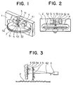
- Figs. 1 and 2 are a perspective view and a front view of a barometric measuring portion of a barometer of the present invention, respectively, a disc-shaped vacuum chamber 2 is secured to a frame 1 at one of its major surfaces and has a movable portion at the center of the other major surface. Two vacuum chambers 2 may be used in a tandem relationship for a more sensitive measurement.
- the movable portion has an aperture plate 3 mounted thereon by a mounting fitting 32 attached to the vacuum chamber 2.
- the aperture plate 3 has formed therein an aperture 31 which is a slit extending perpendicularly to the direction of movement of the moving portion of the vacuum chamber in the illustrated embodiment.
- the aperture 31 may be circular or rectangular or other shapes, but the slit as illustrated is preferable.
- the frame 1 has also mounted thereon, at the both sides of the slit plate 3, a light source 4 which is a light-emitting diode and an optical position detector 5 which is a semiconductor device using the above photo-electric conduction effect.
- a semiconductor optical position detector may be one commercially available from Hamamatsu Photonics Kabushiki Kaisha under the trade name of "position sensitive detector” Type S1543 or Type S1771.
- the light source 4 is mounted to the frame 1 by a light source holder 41 and the optical position detector 5 is mounted to a detector mounting plate 51 which in turn is secured to the frame 1 by a detector holder 52.
- the optical position detector 5 has a light-receiving surface 53. As best seen from Fig.
- the detector 5 has a pair of elongated parallel electrodes 55 and 56 at the upper and the lower edges of the light-receiving surface 53 and is reverse biased by an electric source 57.
- an electric current flows from that region toward each of the electrodes 55 and 56.
- the magnitudes of the current flowing into the electrodes 55 and 56 depend on the light amount the light receiving region receives and the resistance of the current path which is proportional to its length.
- Fig. 3 The measurement of the displacement due to the elastic deformation of the vacuum chamber 2 is as illustrated in Fig. 3 illustrating the optical principle.
- the light source 4, the aperture in the form of the slit 31 of the aperture plate 3 mounted on the vacuum chamber 2, and the semiconductor optical position detector 5 are optically coupled as shown in the drawing.
- the displacement of the movable portion of the vacuum chamber 2 due to the elastic deformation of the vacuum chamber 2 and therefore the displacement of the slit 31 is measured as the amount of movement of the projection of the slit on the light-receiving surface 53 of the optical position detector 5 or the light impinging position 54.
- the distance between the impinging light position 54 on the light receiving surface 53 of the optical position detector 5 and the electrode 56 (B) is x
- the resistance therebetween is R B
- the resistance between the light impinging position 54 and the electrode 55 (A) is R A
- the distance between the electrode 55 and the electrode 56 is L.
- the photo-electric current generated in proportion to the incoming light amount of the incoming light 42 at the light impinging position 54 is distributed in inverse proportion to the resistances R A and R B and flows out from the electrode 55 and the electrode 56 as the currents Ia and Ib, respectively. Therefore, the relationship between the current and the resistance is: Assume that the distance x and the resistance R B are proportional, Therefore, the displacement of the vacuum chamber can be obtained by measuring Ia.
- Ia + Ib is the total amount of the photo-electric current generated at the light impinging position 54, so that the values Ia and x can be made perfectly proportional when the above toal value Ia + Ib can be made constant by adjusting the light incoming amount.
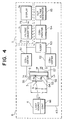
- the barometric meter of the present invention comprises an automatic control circuit 6 as shown in Fig. 4.
- the automatic control circuit 6 comprises a pair of current-to-voltage converters 61 and 62 connected to the first and the second electrodes 55 and 56, respectively.
- the outputs of the current-to-voltage converters 61 and 62 are connected to an adder 63 where the voltage signals Vi1 and Vi2 corresponding to the currents Ia and Ib are added.
- the adder 63 is then connected to a comparator 64, where the added voltage signal from the adder 63 is compared with a reference voltage signal supplied from a reference signal generator 65.
- the output from the comparator 64 is connected through an adjusting signal line 43 to the light source controller 66 which adjusts the intensity of the light emitted from the light source 4 according to the output adjusting signal from the comparator 64. Therefore, the sum of the photo-electric currents Ia and Ib is always maintained equal to the constant reference value.
- Ia + Ib is constant substantially irrespective of the directionality of the light source, directional change of the incoming light 42 due to the slit position change and the change in the distance between the light source and the light impinging position.
- the barometric meter of the present invention further comprises a display unit 7.
- the display unit 7 comprises a voltage converter 71 connected at its input 72 to the first current-to-voltage converter 61 and a digital display 74 connected to an output 73 of the voltage converter 71.
- the amount Ia proportional to the displacement x of the light impinging position is taken out as a voltage Vi at the output of the current-voltage converter 61.
- This voltage is converted by the voltage converter 71 of the display 7 into a voltage Vo of a numerical value which is equal to the numerical value of the air pressure or altitude, and read as a voltage by a digital display 74 similar to a ordinary digital display voltmeter and displayed as the pressure or altitude.
- Fig. 5 illustates the detail of the voltage converter 71 shown in Fig. 4.
- the voltage converter 71 comprises an amplifier 711 connected to the output of the current-to-voltage converter 61 (Fig. 4).
- the output of the amplifier 711 is connected to one of inputs of an adder 712 of which the other inputs is connected to an adjustable voltage generator 713.
- the adder 712 adds the outputs from the amplifier 711 and the adjustable voltage generator 713 to supply an output Vo to the digital display 74 (Fig. 4).
- equation (5) is an approximate equation for a range of altitude of from 0 m to 3000 m, which provides an error equal to or less than 5% with respect to the geopotential altitude.
- Table 1 Air Pressure mbar x mm Vi mV Vo mV 1000 0.5 100 1000 500 1.5 300 500
- Table 2 Altitude m x mm Vi mV Vo mV 0 0.5 100 0 2500 1.0 200 2500
- the voltage converter 71 achieves the conversions of the above equations (6) and (7).
- an amplifier 711 is for calculating the first term of the right side of the equation (3) or (6) and (7), and the constant K1 designates its gain or loss.
- a variable resistor 713 is a generator of the constant K2 and calculating the right side of the equation (3) or (6) and (7) by an adder 712.
- the axis of abscisa represents the displacement x of the vacuum chamber and the axis of ordinate represents respective values corresponding to the air pressure and the barometric altitude
- solid lines in the both figures representing the equations (6) and (7) against the variation of x
- dotted lines representing the first terms of the right side of the respective equations
- the distances (the differences along the axis of ordinate) between the solid and dotted lines representing the second term of the right side of the equations.
- the barometric meter such as the barometer or the barometric altimeter of the present invention as above constructed comprises a light source 4, a slit plate 3 with a slit 31 fixedly mounted on a vacuum chamber 2 and an optical position detector 5 as shown in a diagram showing the optical principle of Fig. 3, with a mechanical connecting mechanism as in the conventional barometer eliminated.
- the light emitted from the light source 4 is irradiated on the optical position detector 5 through the slit 31 of the slit plate 3, and the displacement of the vacuum chamber 2 to which the slit plate 3 is mounted is grasped as the positional change of the light incoming through the slit 31 onto the optical position detector 5 and this displacement is measured and displayed.
- the slit plate 3 is not unnecessary load for the vacuum chamber when its atitude changes since the slit plate 3 is light-weight, and since the displacement of the incoming light 54 or the projection of the slit 31 on the light-receiving surface 53 of the optical position detector 5 is measured, there is no room for the errors due to instability of the contact resistance of the slider or the like in the sliding resistor.
- a barometric meter having a very high precision than that of the conventional design can be manufactured by utilizing an optical position detector of a higher sensitivity and superior resolution with respect to the displacement of the vacuum chamber.
- the photo-electric current generated at a position at which the incoming light impinges on the light-receiving surface is maintained constant by providing an automatic control circuit for adjusting the intensity of the light source, and by providing a circuit which converts the output from the optical position detector into a predetermiend numerical value, such as a numerical value indicative of the air pressure for the barometer or a numerical value indicative of the altitude for the altimeter, the device can be used as a directly readable digital instument.
- the barometric meter of the present invention can be easily modified between a barometer in which the air pressure is measured and converted into a numerical value indicative of the air pressure and a barometric altimeter in which the measured air pressure is converted into barometric altitude.
- the present invention utilizes an optical system in the portion for reading out the displacement of the vacuum chamber, so that the present invention exhibits the following advantages as a barometric meter including a barometer or a barometric altimeter.
- the present invention has an overwhelming superior usefulness as compared to the conventional art.
Landscapes
- Physics & Mathematics (AREA)
- General Physics & Mathematics (AREA)
- Measuring Fluid Pressure (AREA)
Claims (10)
- Un dispositif de mesure barométrique comprenant :
une chambre à vide (2) comportant une portion mobile qui se déplace en fonction de la pression d'air atmosphérique ;
une source de lumière (4) qui est stationnaire par rapport à ladite portion mobile de la chambre à vide (2) ;
un diaphragme (3) relié à ladite portion mobile de la chambre à vide (2) pour effectuer un mouvement avec celui-ci, ledit diaphragme (3) ayant une ouverture (31) réalisée dans celui-ci pour permettre à un faisceau de lumière émis par ladite source de lumière (4) de passer à travers cette fente ;
un détecteur de position photoélectrique (5), disposé à l'autre côté du diaphragme (3) par rapport à ladite source de lumière (4) et stationnaire par rapport à la portion mobile de la chambre à vide (2) et comprenant une surface réceptrice de lumière (53) pour recevoir le faisceau de lumière qui passe à travers ladite ouverture (31) dans ledit diaphragme (3) pour engendrer un signal photoélectrique dans une région réceptrice de lumière (54) de celle-ci, dans laquelle le faisceau de lumière frappe le détecteur de position photoélectrique (5) ;
des moyens de reproduction (74) reliés au détecteur de position photoélectrique (5) pour représenter ou afficher une indication qui dépend du signal photoélectrique ; et
un circuit de commande ou de contrôle automatique pour commander ou contrôler automatiquement la luminance de la source de lumière (4) de façon que la quantité de lumière reçue par la région réceptrice de lumière (54) du détecteur de position photoélectrique (5) soit maintenue constante, caractérisé en ce que l'indication engendrée par les moyens d'affichage ne dépend pas de plus d'un signal de sortie dudit détecteur de position photoélectrique. - Un baromètre selon la revendication 1, dans lequel l'ouverture précitée (31) dans le diaphragme précité (3) est une fente allongée s'étendant dans la direction perpendiculaire à la direction de mouvement de la portion mobile précitée de la chambre à vide (2) précitée.
- Un dispositif de mesure barométrique selon la revendication 1, dans lequel l'ouverture précitée (31) dans le diaphragme précité a une largeur et une longueur qui sont sensiblement égales.
- Un dispositif de mesure barométrique selon la revendication 1, dans lequel les moyens d'affichage précités (74) sont formés par un dispositif à affichage numérique.
- Un dispositif de mesure barométrique selon la revendication 1, dans lequel les moyens d'affichage ou de reproduction (74) comprennent des moyens pour convertir le signal photoélectrique précité en une valeur numérique indicative de la pression d'air.
- Dispositif de mesure barométrique selon la revendication 1, dans lequel les moyens d'affichage précités (74) comprennent des moyens pour convertir le signal photoélectrique précité en une valeur numérique indicative d'une altitude.
- Un dispositif de mesure barométrique selon la revendication 1, dans lequel les moyens d'affichage ou de reproduction précités (74) comprennent un convertisseur de tension (71) relié au détecteur de position photoélectrique précité pour convertir son signal d'entrée Vi fourni par le détecteur de position photoélectrique précité en une tension de sortie Vo selon

où K₁ et K₂ sont des constantes. - Un dispositif de mesure barométrique selon la revendication 7, dans lequel le convertisseur de tension précité (71) comprend un amplificateur relié au détecteur de position photoélectrique précité (5) pour amplifier le signal de sortie du détecteur de position d'un facteur K₁, un générateur de tension ajustable (713) pour engendrer une tension constante K₂, et un additionneur (712) relié par ses sorties audit amplification (711) et au générateur de tension (713) pour fournir une tension de sortie qui est une somme dudit signal de sortie du détecteur de position (5) multiplié par K₁ et de la tension constante K₂.
- Un dispositif de mesure barométrique selon la revendication 1, dans lequel le détecteur de position photoélectrique précité (5) comprend une électrode (55, 56) reliée à la surface réceptrice de lumière précitée (53) pour recueillir un signal de courant photoélectrique (Ia, Ib) de la région réceptrice de lumière (54) et un convertisseur courant-tension (61, 62) relié à ladite électrode (55, 56) pour convertir ledit signal de courant photoélectrique (Ia, Ib) en un signal de tension.
- Un dispositif de mesure barométrique selon la revendication 1, dans lequel le circuit de commande ou de contrôle automatique précité comprend une paire d'électrodes (55, 56) montées à une distance l'une de l'autre sur le détecteur de position photoélectrique précité (5) pour recueillir ou collecter le courant photoélectrique précité (Ia, Ib) engendré dans la région réceptrice de lumière ; une paire de convertisseurs, courant-tension (61, 62) chacun relié à ladite paire d'électrodes (55, 56) pour convertir lesdits courants photoélectriques (Ia, Ib) en signaux de sortie de tension, un additionneur (63) relié par ses entrées auxdits convertisseurs courant-tension (61, 62) pour établir une somme desdits signaux de sortie de tension pour fournir celle-ci, un générateur de signal de référence (65) pour fournir un signal de tension de référence, un comparateur (64) monté entre ledit additionneur (63) et ledit générateur de signal de référence (65) pour établir un signal de différence entre ceux-ci et un circuit de commande ou de contrôle de luminance pour ajuster la luminance de ladite source de lumière.
Applications Claiming Priority (2)
| Application Number | Priority Date | Filing Date | Title |
|---|---|---|---|
| JP256508/87 | 1987-10-12 | ||
| JP62256508A JPH0198934A (ja) | 1987-10-12 | 1987-10-12 | 気圧計又は気圧高度計 |
Publications (3)
| Publication Number | Publication Date |
|---|---|
| EP0312332A2 EP0312332A2 (fr) | 1989-04-19 |
| EP0312332A3 EP0312332A3 (fr) | 1991-02-20 |
| EP0312332B1 true EP0312332B1 (fr) | 1995-02-22 |
Family
ID=17293603
Family Applications (1)
| Application Number | Title | Priority Date | Filing Date |
|---|---|---|---|
| EP88309549A Expired - Lifetime EP0312332B1 (fr) | 1987-10-12 | 1988-10-12 | Baromètre |
Country Status (4)
| Country | Link |
|---|---|
| US (1) | US4938062A (fr) |
| EP (1) | EP0312332B1 (fr) |
| JP (1) | JPH0198934A (fr) |
| DE (1) | DE3853121T2 (fr) |
Cited By (1)
| Publication number | Priority date | Publication date | Assignee | Title |
|---|---|---|---|---|
| US11662200B2 (en) | 2018-04-18 | 2023-05-30 | Logicdata Electronic & Software Entwiclungs Gmbh | Sensor assembly, actuator, control system, electrically adjustable piece of furniture and method for operating an electrically adjustable piece of furniture |
Families Citing this family (8)
| Publication number | Priority date | Publication date | Assignee | Title |
|---|---|---|---|---|
| US5132531A (en) * | 1990-11-07 | 1992-07-21 | Eaton Corporation | Translational position sensing apparatus employing rotating element and PSD |
| US5130556A (en) * | 1990-11-07 | 1992-07-14 | Eaton Corporation | Photoelectric fiber thickness and edge position sensor |
| DE69425437T2 (de) * | 1994-05-30 | 2001-01-25 | Nagano Keiki Seisakusho Ltd., Tokio/Tokyo | Restdruckwandler |
| USH1937H1 (en) * | 1996-02-29 | 2001-02-06 | The United States Of America As Represented By The United States Department Of Energy | Laser barometer |
| US20040186635A1 (en) * | 2003-03-21 | 2004-09-23 | Manfred Mark T. | Methods and apparatus for correctly adjusting barometric pressure settings on barometric altimeters |
| US7894079B1 (en) * | 2009-11-09 | 2011-02-22 | Mitutoyo Corporation | Linear displacement sensor using a position sensitive photodetector |
| US8400643B2 (en) | 2011-04-15 | 2013-03-19 | Mitutoyo Corporation | Displacement sensor using multiple position sensitive photodetectors |
| JP2015216571A (ja) * | 2014-05-13 | 2015-12-03 | ルネサスエレクトロニクス株式会社 | 光結合回路、光結合回路の受光装置及び信号処理装置 |
Family Cites Families (12)
| Publication number | Priority date | Publication date | Assignee | Title |
|---|---|---|---|---|
| US3308303A (en) * | 1963-06-28 | 1967-03-07 | Brunswick Corp | Transducer system employing electro-optical means |
| US3612881A (en) * | 1969-04-14 | 1971-10-12 | Cessna Aircraft Co | Relative movement detector |
| US3590259A (en) * | 1970-04-20 | 1971-06-29 | Kinemotive Corp | Chopper stabilized photoelectric transducer |
| US3916185A (en) * | 1974-03-01 | 1975-10-28 | Bendix Corp | Circuitry for encoding altimeter |
| DE2606434C2 (de) * | 1976-02-18 | 1985-11-28 | Wolfgang Dipl.-Phys.Dr.-Ing. 5413 Bendorf Schulz | Vorrichtung zur Messung von Kräften durch optoelektronische Bestimmung der Verformung von Prüfkörpern |
| US4109147A (en) * | 1976-05-10 | 1978-08-22 | Dresser Industries, Inc. | Optical position sensor |
| US4086488A (en) * | 1976-10-18 | 1978-04-25 | General Medical Appliance Research Corporation | Digital pressure gauge system |
| GB2049955B (en) * | 1979-05-31 | 1983-10-19 | Nat Res Dev | Refractometer |
| DE3124258A1 (de) * | 1980-12-31 | 1982-08-05 | Claudio Dipl.-Ing. 4600 Dortmund Möller | "verfahren und geraet zur messung und/oder registrierung kleinster bewegungen eines messkoerpers, z.b. zur messung und/oder registrierung der bewegung einer aneroidbarometer-druckdose |
| JPS5946329B2 (ja) * | 1981-01-06 | 1984-11-12 | 東京航空計器株式会社 | 誤差補正機構を有するサ−ボ式空盒計器 |
| DE3222462A1 (de) * | 1982-06-15 | 1983-12-15 | KE Morander AB, 44302 Lerum | Einrichtung zur bestimmung des realen oder des virtuellen abstandes einer lichtquelle von einer messebene |
| US4665747A (en) * | 1985-04-19 | 1987-05-19 | Muscatell Ralph P | Flight instrument using light interference for pressure sensing |
-
1987
- 1987-10-12 JP JP62256508A patent/JPH0198934A/ja active Pending
-
1988
- 1988-10-11 US US07/255,949 patent/US4938062A/en not_active Expired - Fee Related
- 1988-10-12 DE DE3853121T patent/DE3853121T2/de not_active Expired - Fee Related
- 1988-10-12 EP EP88309549A patent/EP0312332B1/fr not_active Expired - Lifetime
Cited By (1)
| Publication number | Priority date | Publication date | Assignee | Title |
|---|---|---|---|---|
| US11662200B2 (en) | 2018-04-18 | 2023-05-30 | Logicdata Electronic & Software Entwiclungs Gmbh | Sensor assembly, actuator, control system, electrically adjustable piece of furniture and method for operating an electrically adjustable piece of furniture |
Also Published As
| Publication number | Publication date |
|---|---|
| DE3853121T2 (de) | 1995-10-26 |
| EP0312332A2 (fr) | 1989-04-19 |
| EP0312332A3 (fr) | 1991-02-20 |
| US4938062A (en) | 1990-07-03 |
| DE3853121D1 (de) | 1995-03-30 |
| JPH0198934A (ja) | 1989-04-17 |
Similar Documents
| Publication | Publication Date | Title |
|---|---|---|
| US5101570A (en) | Inclination angle detector | |
| GB1473233A (en) | Gauging method and apparatus | |
| US8184277B2 (en) | Reflection optical sensor for determining the angular position of a rotating element | |
| EP0312332A2 (fr) | Baromètre | |
| US4484069A (en) | Apparatus and method for sensing distance | |
| US4436418A (en) | Distance detector device | |
| JPH0345772B2 (fr) | ||
| US4825069A (en) | Relative movement sensor | |
| Song et al. | Design and performance analysis of laser displacement sensor based on position sensitive detector (PSD) | |
| Makynen et al. | Linear and sensitive CMOS position-sensitive photodetector | |
| US4516020A (en) | Light-operated proximity detector with linear output | |
| GB2151779A (en) | Photoelectric displacement-detection apparatus | |
| JPH0431335B2 (fr) | ||
| US2977499A (en) | Electronic drift compensator | |
| USH746H (en) | Solar reference flight roll position sensor | |
| JPS61104202A (ja) | 光変位計 | |
| JPH0433164B2 (fr) | ||
| JPS6042886B2 (ja) | 測長装置 | |
| JPS623609A (ja) | 測距装置 | |
| JPH0638069B2 (ja) | 示差屈折計 | |
| JPH07183620A (ja) | 半導体レーザを利用した多機能センサー | |
| JPH0371041B2 (fr) | ||
| SU901816A1 (ru) | Устройство дл определени малых рассто ний | |
| JPS6264904A (ja) | 形状測定装置 | |
| JPS629841B2 (fr) |
Legal Events
| Date | Code | Title | Description |
|---|---|---|---|
| PUAI | Public reference made under article 153(3) epc to a published international application that has entered the european phase |
Free format text: ORIGINAL CODE: 0009012 |
|
| AK | Designated contracting states |
Kind code of ref document: A2 Designated state(s): CH DE FR GB IT LI SE |
|
| PUAL | Search report despatched |
Free format text: ORIGINAL CODE: 0009013 |
|
| AK | Designated contracting states |
Kind code of ref document: A3 Designated state(s): CH DE FR GB IT LI SE |
|
| 17P | Request for examination filed |
Effective date: 19910724 |
|
| 17Q | First examination report despatched |
Effective date: 19920505 |
|
| GRAA | (expected) grant |
Free format text: ORIGINAL CODE: 0009210 |
|
| AK | Designated contracting states |
Kind code of ref document: B1 Designated state(s): CH DE FR GB IT LI SE |
|
| REF | Corresponds to: |
Ref document number: 3853121 Country of ref document: DE Date of ref document: 19950330 |
|
| ITF | It: translation for a ep patent filed | ||
| ET | Fr: translation filed | ||
| PLBE | No opposition filed within time limit |
Free format text: ORIGINAL CODE: 0009261 |
|
| STAA | Information on the status of an ep patent application or granted ep patent |
Free format text: STATUS: NO OPPOSITION FILED WITHIN TIME LIMIT |
|
| 26N | No opposition filed | ||
| PGFP | Annual fee paid to national office [announced via postgrant information from national office to epo] |
Ref country code: SE Payment date: 19981006 Year of fee payment: 11 |
|
| PGFP | Annual fee paid to national office [announced via postgrant information from national office to epo] |
Ref country code: FR Payment date: 19981009 Year of fee payment: 11 |
|
| PGFP | Annual fee paid to national office [announced via postgrant information from national office to epo] |
Ref country code: GB Payment date: 19981016 Year of fee payment: 11 Ref country code: DE Payment date: 19981016 Year of fee payment: 11 |
|
| PGFP | Annual fee paid to national office [announced via postgrant information from national office to epo] |
Ref country code: CH Payment date: 19981022 Year of fee payment: 11 |
|
| PG25 | Lapsed in a contracting state [announced via postgrant information from national office to epo] |
Ref country code: GB Free format text: LAPSE BECAUSE OF NON-PAYMENT OF DUE FEES Effective date: 19991012 |
|
| PG25 | Lapsed in a contracting state [announced via postgrant information from national office to epo] |
Ref country code: SE Free format text: THE PATENT HAS BEEN ANNULLED BY A DECISION OF A NATIONAL AUTHORITY Effective date: 19991030 |
|
| PG25 | Lapsed in a contracting state [announced via postgrant information from national office to epo] |
Ref country code: LI Free format text: LAPSE BECAUSE OF NON-PAYMENT OF DUE FEES Effective date: 19991031 Ref country code: CH Free format text: LAPSE BECAUSE OF NON-PAYMENT OF DUE FEES Effective date: 19991031 |
|
| GBPC | Gb: european patent ceased through non-payment of renewal fee |
Effective date: 19991012 |
|
| REG | Reference to a national code |
Ref country code: CH Ref legal event code: PL |
|
| EUG | Se: european patent has lapsed |
Ref document number: 88309549.9 |
|
| PG25 | Lapsed in a contracting state [announced via postgrant information from national office to epo] |
Ref country code: FR Free format text: LAPSE BECAUSE OF NON-PAYMENT OF DUE FEES Effective date: 20000630 |
|
| PG25 | Lapsed in a contracting state [announced via postgrant information from national office to epo] |
Ref country code: DE Free format text: LAPSE BECAUSE OF NON-PAYMENT OF DUE FEES Effective date: 20000801 |
|
| REG | Reference to a national code |
Ref country code: FR Ref legal event code: ST |
|
| PG25 | Lapsed in a contracting state [announced via postgrant information from national office to epo] |
Ref country code: IT Free format text: LAPSE BECAUSE OF NON-PAYMENT OF DUE FEES Effective date: 20051012 |