EP0312409A2 - Ultraschallantriebsvorrichtung - Google Patents
Ultraschallantriebsvorrichtung Download PDFInfo
- Publication number
- EP0312409A2 EP0312409A2 EP88309706A EP88309706A EP0312409A2 EP 0312409 A2 EP0312409 A2 EP 0312409A2 EP 88309706 A EP88309706 A EP 88309706A EP 88309706 A EP88309706 A EP 88309706A EP 0312409 A2 EP0312409 A2 EP 0312409A2
- Authority
- EP
- European Patent Office
- Prior art keywords
- metal block
- stator
- set forth
- electrodes
- stators
- Prior art date
- Legal status (The legal status is an assumption and is not a legal conclusion. Google has not performed a legal analysis and makes no representation as to the accuracy of the status listed.)
- Withdrawn
Links
- 229910052751 metal Inorganic materials 0.000 claims abstract description 45
- 239000002184 metal Substances 0.000 claims abstract description 45
- 230000000750 progressive effect Effects 0.000 claims abstract description 26
- 238000005452 bending Methods 0.000 claims abstract description 11
- 150000001875 compounds Chemical class 0.000 claims description 4
- 238000013329 compounding Methods 0.000 abstract description 3
- 239000000919 ceramic Substances 0.000 description 10
- 230000010363 phase shift Effects 0.000 description 2
- 230000002250 progressing effect Effects 0.000 description 2
- 239000004411 aluminium Substances 0.000 description 1
- 229910052782 aluminium Inorganic materials 0.000 description 1
- XAGFODPZIPBFFR-UHFFFAOYSA-N aluminium Chemical compound [Al] XAGFODPZIPBFFR-UHFFFAOYSA-N 0.000 description 1
- 238000013459 approach Methods 0.000 description 1
- 230000008602 contraction Effects 0.000 description 1
- 230000005284 excitation Effects 0.000 description 1
- 239000003973 paint Substances 0.000 description 1
- 230000009466 transformation Effects 0.000 description 1
Images


Classifications
-
- H—ELECTRICITY
- H02—GENERATION; CONVERSION OR DISTRIBUTION OF ELECTRIC POWER
- H02N—ELECTRIC MACHINES NOT OTHERWISE PROVIDED FOR
- H02N2/00—Electric machines in general using piezoelectric effect, electrostriction or magnetostriction
- H02N2/0005—Electric machines in general using piezoelectric effect, electrostriction or magnetostriction producing non-specific motion; Details common to machines covered by H02N2/02 - H02N2/16
- H02N2/001—Driving devices, e.g. vibrators
- H02N2/003—Driving devices, e.g. vibrators using longitudinal or radial modes combined with bending modes
- H02N2/0035—Cylindrical vibrators
-
- H—ELECTRICITY
- H02—GENERATION; CONVERSION OR DISTRIBUTION OF ELECTRIC POWER
- H02N—ELECTRIC MACHINES NOT OTHERWISE PROVIDED FOR
- H02N2/00—Electric machines in general using piezoelectric effect, electrostriction or magnetostriction
- H02N2/02—Electric machines in general using piezoelectric effect, electrostriction or magnetostriction producing linear motion, e.g. actuators; Linear positioners ; Linear motors
- H02N2/026—Electric machines in general using piezoelectric effect, electrostriction or magnetostriction producing linear motion, e.g. actuators; Linear positioners ; Linear motors by pressing one or more vibrators against the driven body
-
- H—ELECTRICITY
- H02—GENERATION; CONVERSION OR DISTRIBUTION OF ELECTRIC POWER
- H02N—ELECTRIC MACHINES NOT OTHERWISE PROVIDED FOR
- H02N2/00—Electric machines in general using piezoelectric effect, electrostriction or magnetostriction
- H02N2/10—Electric machines in general using piezoelectric effect, electrostriction or magnetostriction producing rotary motion, e.g. rotary motors
- H02N2/103—Electric machines in general using piezoelectric effect, electrostriction or magnetostriction producing rotary motion, e.g. rotary motors by pressing one or more vibrators against the rotor
Definitions
- the present invention relates to an ultrasonic driving device generating a linear progressive wave owing to a compound of a bending vibration of an end bending vibration with longitudinal vibration of an end portion of a stator.
- two groups of electrodes are attached to one end of a ring type piezoelectric ceramic.
- the two groups of electrodes are so positioned that standing waves respectively generated by the two groups of electrodes are shifted every ⁇ /2 in each position.
- the parts of the ring type piezoelectric ceramics corresponding to the electrode are alternately polarized in reverse.
- the two groups of electrodes are respectively connected to two oscillators for respectively generating alternating current voltages having ⁇ /2 phase shift relative to each other.
- the progressive wave is shifted to the circumferential direction of the ring type piezoelectric ceramics, but the progressive wave is not shifted linearly.
- an ultrasonic motor having a Langevin type vibrator comprising two metal blocks, two ring type piezoelectic vibrators, two electrodes between the two metal blocks and a bolt for fixing the two metal blocks, the two piezoelectric ceramics and electrodes.
- a twisting joint body is combined with one metal block with the bolt and a rotary member is pressed by a spring on the twisting joint body.
- an ellipse vibration is generated in the circumferential direction on the twisting joint body in the above ultrasonic motor, but the ellipse vibration is not shifted linearly.
- an asymmetric Langevin type bolt-fixing vibrator generates a progressive wave on its end and side portions. This progressive wave is generated in the direction of the screw of the bolt for fixing a long metal block, a short metal block and two piezoelectric vibrators of an asymmetric Langevin type bolt-fixing vibrator, because of the longitudinal vibration of the piezoelectric vibrator, when AC voltage is applied to the piezoelectric vibrator.
- a rotary member is rotated smoothly when the rotary member is pressed on the end or the side portions of the asymetric Langevin type bolt-fixing vibrator. Therefore the inventor has proposed an ultrasonic driving device with the asymmetric Langevin type bolt-fixing vibrator (see Japanese Patent Application No. 48517/87).
- the primary object of the present invention to provide an ultrasonic driving device generating a progressive wave progressing to one direction on the end portions of a stator.
- the present invention comprises a stator fixing a long metal block, a short metal block, a ring type piezoelectric vibrator and electrodes as one body by engaging the screws of the long metal block and the short metal block with the screws of the both end of a bolt, a member to be driven composed on the one end portion of the stator, and a power supply for supplying alternative current voltage through the electrodes to the piezoelectrode vibrator, whereby progressive wave is generated on the both sides of the stator by compounding longitudinal vibration with bending vibration generated by the stator and drives the member.
- a ring type piezoelectric ceramic B is attached to a ring type resilient member A and the piezoelectric vibrator B vibrates with the resilient member A.
- the piezoelectric ceramic B is divided into 17 parts by the ratio of e.g. 22.5° or 11.25°.
- the respective neighbouring portions in the 17 parts of the piezoelectric vibrator B are polarized by the reverse polarity to each other as shown in Fig. 2.
- the two portions C and D in the one side of the piezoelectric vibrator B are respectively formed as electrodes by conductive paint as shown in Fig. 2.
- the portions G in Fig. 2 show earth electrodes.
- the member F to be driven, to which slider E is attached, is mounted on the resilient member A.
- an alternating current voltage of V0 sin ⁇ t is applied to the one electrode C and an alternating current voltage V0 cos ⁇ t is applied to the other electrode D, where V0 is the instantaneous value, ⁇ is radian frequency and t is time.
- V0 is the instantaneous value
- ⁇ is radian frequency
- t is time.
- the phases of these voltages are shifted by ⁇ /2 relative to each other.
- the progressive wave is rotated along by the ring resilient member, but is not shifted linearly.
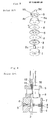
- a piezoelectric vibrator 3, a terminal plate 4, a piezoelectric vibrator 5, a terminal plate 6 and an aluminium disk are put on a washer 1 and a bolt 2 is inserted through the centre holes of these members.
- the screw 2a of the bolt 2 is engaged with the screw hole 8a of a twisting joint body 8, arcuate projections 8c are formed on both sides of drain 8b and a beam 8d is so formed in the upper portion of the twisting joint body 8 that the beam 8d and drain 8b are at a predetermined angle.
- a rotary member 9 is put on the twisting joint body 8
- a centre bolt 10 passed through holes of a bearing 11 of the rotary member 9 is fixed to the twisting joint body 8
- a spring 12 is attached between the upper end of the bolt 10 and the bearing 11, whereby the rotary member 9 is strongly pressed against the beam 8d of the twisting joint body 8 and is rotated with the elliptic vibration of the beam 8d.
- screws 13a and 14a are formed in the one ends of a long metal block 13 and a short metal block 14 respectively.
- a bolt 15 is inserted into holes in two piezoelectric vibrators 16 and 17 and two electrodes 18 and 19 and the screws 15a and 15b of the ends of bolt 15 are engaged with the screws 13a and 14a.
- a stator 21 is composed.
- An alternating current supply 20 is connected to the terminals 18a and 19a of the electrodes 18 and 19.
- stator 21 is very much longer than the ultrasonic driving device presented by the inventor.
- the ultrasonic driving device having the stator of the Langevin type vibrator when the length of the long metal block is slightly longer than that of the short metal block, twist vibration due to the screw of the bolt arises on the end portions and side portion of the stator.
- the progressive wave to one direction arises by compounding the longitudinal vibration with the bending vibration.
- This linear progressive wave generates to a determined direction when the alternating current voltage of the resonant frequency is applied from terminals 18a and 19a through the electrodes 18 and 19 to the piezoelectric vibrators 16 and 17.
- the direction of the progressive wave is decided due to a distance between the respective start portions of the screws of the bolt and the piezoelectric vibrators 16 and 17 and the shift from the centre of the piezoelectric vibrators 16 and 17.
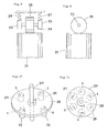
- a rotary shaft 29 of a disk 28 is rotatably supported with bearings.
- Four stators 21 are pressed against one side of the disk 28.
- the stators 21 respectively generate linear progressive waves in the rotary direction of the disk 28 as shown by arrows A in Fig. 10. Therefore, the disk 28, is rotated as shown by an arrow B.
- a plate member 30 to be driven is supported by roller bearings to be driven linearly and two stators 21 are pressed under the surface of the plate member 30.
- the plate member 30 When the alternating current voltage is applied to the two stators 21, the plate member 30 is driven in the directions of the arrows A or B with the progressive wave of the respective stator 21.
- three or four stators 21 are attached to the bottom portion of a member to be driven, the directions of the progressive waves of the three or four stators 21 are made coincident and the respective end surfaces of the three or four stators 21 are put on a plane floor.
- the alternating current voltage is applied to the respective piezoelectric vibrators 16 and 17 of the three or four stators 21, the member is linearly driven on the plane floor by the progressive wave on the end surfaces of the three or four stators 21.
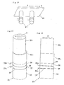
- the piezoelectric vibrators 16 and 17 and the electrodes 18 and 19 having the terminal 18a and 19a are put between two metal blocks 13a and 14 which are fixed with a bolt.
- the length of the metal block 13a is same as that of the metal block 14 or is slightly longer.
- the metal block 13b is formed with a diameter slightly smaller than that of the metal block 13a and the centre of the metal block 13b is slightly shifted from the centre of the metal block 13a.
- the metal block 13b is formed with the metal block 13a by shaving a long metal block, or the other metal block 13b is attached on the end surface of the metal block 13a.
- the linear progressive wave is generated on the end surface of the metal block 13b as shown by arrows A.
- the above stator may be used to drive a member in the same way as the previous examples.
Landscapes
- General Electrical Machinery Utilizing Piezoelectricity, Electrostriction Or Magnetostriction (AREA)
Applications Claiming Priority (2)
| Application Number | Priority Date | Filing Date | Title |
|---|---|---|---|
| JP260186/87 | 1987-10-15 | ||
| JP62260186A JPH01103175A (ja) | 1987-10-15 | 1987-10-15 | 超音波駆動装置 |
Publications (2)
| Publication Number | Publication Date |
|---|---|
| EP0312409A2 true EP0312409A2 (de) | 1989-04-19 |
| EP0312409A3 EP0312409A3 (de) | 1990-03-28 |
Family
ID=17344526
Family Applications (1)
| Application Number | Title | Priority Date | Filing Date |
|---|---|---|---|
| EP88309706A Withdrawn EP0312409A3 (de) | 1987-10-15 | 1988-10-17 | Ultraschallantriebsvorrichtung |
Country Status (2)
| Country | Link |
|---|---|
| EP (1) | EP0312409A3 (de) |
| JP (1) | JPH01103175A (de) |
Cited By (2)
| Publication number | Priority date | Publication date | Assignee | Title |
|---|---|---|---|---|
| DE10329863A1 (de) * | 2003-06-19 | 2005-02-10 | Kingstate Electronics Corp. | Piezokeramischer Wellenantriebs-Ultraschallwellenmotor |
| CN110780200A (zh) * | 2019-12-03 | 2020-02-11 | 哈尔滨理工大学 | 一种基于定子电流复数分量的感应电机匝间短路故障诊断方法 |
Families Citing this family (2)
| Publication number | Priority date | Publication date | Assignee | Title |
|---|---|---|---|---|
| JP2633072B2 (ja) * | 1990-08-03 | 1997-07-23 | キヤノン株式会社 | 振動波駆動装置および振動波駆動装置を用いた装置 |
| KR100511334B1 (ko) * | 2003-10-20 | 2005-08-31 | 엘지전자 주식회사 | 복합웨이퍼를 구비한 냉장고용 피씨비 |
Family Cites Families (2)
| Publication number | Priority date | Publication date | Assignee | Title |
|---|---|---|---|---|
| EP0231940A3 (de) * | 1986-02-04 | 1990-01-17 | Siemens Aktiengesellschaft | Piezoelektrischer Antrieb |
| EP0289734B1 (de) * | 1987-03-18 | 1994-06-01 | Honda Electric Co., Ltd. | Ultraschall-Antriebsanordnung |
-
1987
- 1987-10-15 JP JP62260186A patent/JPH01103175A/ja active Pending
-
1988
- 1988-10-17 EP EP88309706A patent/EP0312409A3/de not_active Withdrawn
Cited By (4)
| Publication number | Priority date | Publication date | Assignee | Title |
|---|---|---|---|---|
| DE10329863A1 (de) * | 2003-06-19 | 2005-02-10 | Kingstate Electronics Corp. | Piezokeramischer Wellenantriebs-Ultraschallwellenmotor |
| DE10329863B4 (de) * | 2003-06-19 | 2011-12-22 | Kingstate Electronics Corp. | Piezokeramischer Wellenantriebs-Ultraschallwellenmotor |
| DE10329863B9 (de) * | 2003-06-19 | 2012-09-27 | Kingstate Electronics Corp. | Piezokeramischer Wellenantriebs-Ultraschallwellenmotor |
| CN110780200A (zh) * | 2019-12-03 | 2020-02-11 | 哈尔滨理工大学 | 一种基于定子电流复数分量的感应电机匝间短路故障诊断方法 |
Also Published As
| Publication number | Publication date |
|---|---|
| EP0312409A3 (de) | 1990-03-28 |
| JPH01103175A (ja) | 1989-04-20 |
Similar Documents
| Publication | Publication Date | Title |
|---|---|---|
| US4893045A (en) | Ultrasonic driving device | |
| JP3118251B2 (ja) | 超音波駆動装置及びその方法 | |
| EP0289734B1 (de) | Ultraschall-Antriebsanordnung | |
| JPS62247870A (ja) | 超音波振動子の駆動制御方法 | |
| EP0301430B1 (de) | Ultraschalltreiberanordnung | |
| JPH0241673A (ja) | 超音波駆動装置 | |
| EP0359875B1 (de) | Ultraschallantriebsanordnungen | |
| KR920015691A (ko) | 초음파 스테핑 모터 및 진동자 구동법 | |
| US4894578A (en) | Ultrasonic driving device | |
| EP0312409A2 (de) | Ultraschallantriebsvorrichtung | |
| US4893046A (en) | Ultrasonic driving device | |
| JP4119903B2 (ja) | 平板型圧電超音波モーター | |
| US4779019A (en) | Electrostriction motor | |
| US5532541A (en) | Ultrasonic motor | |
| JP3297211B2 (ja) | 超音波モータ | |
| JPS62100179A (ja) | 圧電モ−タ | |
| CA1301230C (en) | Ultrasonic driving device | |
| JPH0773428B2 (ja) | 圧電駆動装置 | |
| JPH0744856B2 (ja) | 超音波モータ | |
| JPH08163879A (ja) | 超音波振動子および超音波モータ | |
| JPS63110973A (ja) | 圧電駆動装置 | |
| JPS6344970A (ja) | 超音波振動子とその駆動制御方法 | |
| JP2716423B2 (ja) | 振動発生器 | |
| JP2599920B2 (ja) | 超音波駆動装置 | |
| JPH01308172A (ja) | 超音波駆動装置 |
Legal Events
| Date | Code | Title | Description |
|---|---|---|---|
| PUAI | Public reference made under article 153(3) epc to a published international application that has entered the european phase |
Free format text: ORIGINAL CODE: 0009012 |
|
| AK | Designated contracting states |
Kind code of ref document: A2 Designated state(s): CH DE FR GB IT LI NL SE |
|
| PUAL | Search report despatched |
Free format text: ORIGINAL CODE: 0009013 |
|
| RHK1 | Main classification (correction) |
Ipc: H01L 41/08 |
|
| AK | Designated contracting states |
Kind code of ref document: A3 Designated state(s): CH DE FR GB IT LI NL SE |
|
| 17P | Request for examination filed |
Effective date: 19900921 |
|
| 17Q | First examination report despatched |
Effective date: 19921223 |
|
| STAA | Information on the status of an ep patent application or granted ep patent |
Free format text: STATUS: THE APPLICATION IS DEEMED TO BE WITHDRAWN |
|
| 18D | Application deemed to be withdrawn |
Effective date: 19940312 |