EP0312749A2 - Procédé et dispositif pour prélever des imprimés d'une roue à aubes à mécanisme rotatif d'une machine d'imprimerie - Google Patents
Procédé et dispositif pour prélever des imprimés d'une roue à aubes à mécanisme rotatif d'une machine d'imprimerie Download PDFInfo
- Publication number
- EP0312749A2 EP0312749A2 EP88114556A EP88114556A EP0312749A2 EP 0312749 A2 EP0312749 A2 EP 0312749A2 EP 88114556 A EP88114556 A EP 88114556A EP 88114556 A EP88114556 A EP 88114556A EP 0312749 A2 EP0312749 A2 EP 0312749A2
- Authority
- EP
- European Patent Office
- Prior art keywords
- printed products
- drivers
- conveyor
- paddle wheel
- support member
- Prior art date
- Legal status (The legal status is an assumption and is not a legal conclusion. Google has not performed a legal analysis and makes no representation as to the accuracy of the status listed.)
- Granted
Links
- 238000000034 method Methods 0.000 title claims description 5
- 230000015572 biosynthetic process Effects 0.000 abstract description 9
- 239000000969 carrier Substances 0.000 abstract description 6
- 238000011144 upstream manufacturing Methods 0.000 abstract description 2
- 238000006073 displacement reaction Methods 0.000 description 4
- 230000010363 phase shift Effects 0.000 description 2
- 125000006850 spacer group Chemical group 0.000 description 2
- 238000010276 construction Methods 0.000 description 1
- 230000001419 dependent effect Effects 0.000 description 1
- 230000001360 synchronised effect Effects 0.000 description 1
Images

Classifications
-
- B—PERFORMING OPERATIONS; TRANSPORTING
- B65—CONVEYING; PACKING; STORING; HANDLING THIN OR FILAMENTARY MATERIAL
- B65H—HANDLING THIN OR FILAMENTARY MATERIAL, e.g. SHEETS, WEBS, CABLES
- B65H29/00—Delivering or advancing articles from machines; Advancing articles to or into piles
- B65H29/66—Advancing articles in overlapping streams
- B65H29/6609—Advancing articles in overlapping streams forming an overlapping stream
-
- B—PERFORMING OPERATIONS; TRANSPORTING
- B65—CONVEYING; PACKING; STORING; HANDLING THIN OR FILAMENTARY MATERIAL
- B65H—HANDLING THIN OR FILAMENTARY MATERIAL, e.g. SHEETS, WEBS, CABLES
- B65H29/00—Delivering or advancing articles from machines; Advancing articles to or into piles
- B65H29/38—Delivering or advancing articles from machines; Advancing articles to or into piles by movable piling or advancing arms, frames, plates, or like members with which the articles are maintained in face contact
- B65H29/40—Members rotated about an axis perpendicular to direction of article movement, e.g. star-wheels formed by S-shaped members
-
- B—PERFORMING OPERATIONS; TRANSPORTING
- B65—CONVEYING; PACKING; STORING; HANDLING THIN OR FILAMENTARY MATERIAL
- B65H—HANDLING THIN OR FILAMENTARY MATERIAL, e.g. SHEETS, WEBS, CABLES
- B65H2301/00—Handling processes for sheets or webs
- B65H2301/40—Type of handling process
- B65H2301/44—Moving, forwarding, guiding material
- B65H2301/447—Moving, forwarding, guiding material transferring material between transport devices
- B65H2301/4473—Belts, endless moving elements on which the material is in surface contact
- B65H2301/44732—Belts, endless moving elements on which the material is in surface contact transporting articles in overlapping stream
-
- B—PERFORMING OPERATIONS; TRANSPORTING
- B65—CONVEYING; PACKING; STORING; HANDLING THIN OR FILAMENTARY MATERIAL
- B65H—HANDLING THIN OR FILAMENTARY MATERIAL, e.g. SHEETS, WEBS, CABLES
- B65H2301/00—Handling processes for sheets or webs
- B65H2301/40—Type of handling process
- B65H2301/44—Moving, forwarding, guiding material
- B65H2301/447—Moving, forwarding, guiding material transferring material between transport devices
- B65H2301/44765—Rotary transport devices with compartments
Definitions
- the present invention relates to a method and an apparatus for taking over printed products from a rotatingly driven impeller according to the preamble of claims 1 and 3 respectively.
- a device of this type is known for example from EP-OS 0 067 399.
- pairs arranged on two parallel and synchronous revolving carriers run onto the trailing edges of the printed products as soon as the leading edges of these printed products have been released from the pockets of the paddle wheel, and thus align the trailing edges of the printed products at right angles to the conveying direction of the conveyor out.
- the printed products When the printed products are shot into the pockets of the paddle wheel, they may tilt.
- the printed products fall out of their pockets in free fall and are carried along by the printed products already placed on the conveyor and the belts of the conveyor due to friction. It is therefore possible, especially in the case of jammed printed products, for a leading corner to be picked up by lifting belts before the drivers could act on the trailing edge of the jammed printed product.
- printed products on the free fall path between the paddle wheel and the conveyor or the carriers of the driver by the wind Paddle wheel or fluttering of the trailing edges can be influenced in an uncontrolled manner, which can also have the consequence that the distances between individual printed products in the removed scale formation can be uneven and that individual printed products are canted in the scale formation.
- changes in the rotational speed of the paddle wheel can also lead to phase shifts, which result in uneven spacing between the printed products.
- the object of the present invention is to propose a method and a device for taking over printed products from a rotating driven paddle wheel of a printing machine, in which printed products which are also tilted or not completely shot into the paddle wheel are reliably aligned when forming the scale formation, and at which or which the air draft generated by the paddle wheel cannot exert an uncontrolled influence on the printed products.
- the printed products are briefly held at the intersection of the movement path of the drivers and the transport level of the conveyor, until the drivers have passed the intersection. This means that the printed products can only be transported away from the conveyor by the drivers. This will give an exact distance of the printed products as well as a precise alignment of the trailing edge transversely to the conveying direction of the conveyor.
- the printed products are clamped at the intersection between the drivers and a support member and the drivers are disengaged from the printed products by means of the support member. This allows gentle clamping and releasing of the printed products in a simple manner.
- the drivers engage in the pockets of the paddle wheel in front of the crossing point in order to push protruding printed products into the pockets. This ensures that the printed products are pushed all the way into the pockets and that the trailing edges are already aligned on the support member. In particular, the trailing edges are prevented from fluttering.
- the carriers preferably have a pivotably sprung boom, this boom preferably being formed by a first end of a helical spring arranged transversely to the conveying element, the second end of which is adjusted with respect to the conveying element.
- a driver is very simple in construction, since the boom and the spring element form a unit.
- the fixation of the second end is adjustable. This can increase the amount of time that the printed matter is held be set at the crossing point.
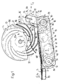
- the paddle wheel 10 of a printing machine is shown purely schematically, which has a plurality of pockets 12 open on its circumference.
- the bottom of the pockets 12 is designated 12a.
- the paddle wheel l0 is rotatable on a stationary shaft 14 stored and is driven in the direction of arrow B with the rotational speed v 1 rotating.
- the paddle wheel 10 is preceded by a folder, not shown, from which the emerging, folded printed products 16, for example newspapers, magazines or parts thereof, fall into the pockets 12 of the paddle wheel 10.
- the printed products 16 emerge from the folder with their folded edge 16a. This fold edge 16a is thus seen in the direction of rotation B of the paddle wheel 10 to the leading edge.
- a conveyor 18 Arranged below the paddle wheel 10 is a conveyor 18, which is followed by a belt conveyor 20 for transporting away the scale formation S formed on the conveyor 18.
- a driver arrangement 22 is connected upstream of the conveyor 18, the movement path of drivers 24 on the conveyor-effective route overlapping the transport plane defined by the conveyor 18 at an intersection 26.
- the conveying direction of the conveyor 18 and the belt conveyor 20 is designated C, that of the driver assembly 22 with G.
- the conveying speed of the conveyor 18 and the belt conveyor 20 is v2.
- bearing elements 30 are arranged in pairs.
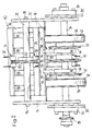
- Two parallel shafts 32, 34 are rotatably mounted on them.
- On the shaft 32 which is driven in the direction of the arrow D, a pair of spaced-apart band rollers 36 are arranged in a rotationally fixed manner.
- the shaft 32 is provided with a chain drive 38 shown in broken lines with the shaft 34, adjustable in phase, operatively connected.
- a sprocket 40 is arranged in a rotationally fixed manner on the shaft 34, while a further pair of belt rollers 42 and deflection sprockets 44 are rotatably mounted on it.
- baffles 46 which coaxially surround this and wedge-shaped against the shaft 32, and two corresponding bobbin rollers are arranged on the shaft 32.
- Analogue deflection sprockets 44 and belt rollers 36 are also provided on the shaft 32.
- Two parallel, endless belts 50 run around the belt rollers 36, 42.
- Two parallel, endless chains 52 are guided around the deflection sprockets 44 arranged on the shafts 32 and 34.
- the deflection sprockets 44 are driven such that the rotational speed of the chains 52 is the same as that of the belts 50.
- Grippers 54 shown in dash-dot lines, are arranged on the chains 52 at fixed intervals.
- the grippers 54 have gripper bodies 56 attached to the side of the chains 2, on which resilient fingers 58 are arranged. In the area of the shafts 32 and 34, the fingers 58 are transferred into the open position shown in dashed lines by means of the scenes 46 or scenery rollers. When the fingers run off the scenes 46 or the scenery rollers, they pass into the clamping position and clamp the trailing edges of the printed products 16 on the conveyor-effective route or rest on the gripper body 56 on the route which is not conveyor-effective. Only one pair of grippers 54 is shown in FIGS. 1 and 2.
- the shaft 32 is by means of a further chain drive 60 with the output of a differential gear 62 also rotatably mounted on the side plates 28, 28 ' bound.
- a chain-dotted chain 64 of another chain drive 66 wraps around with the aid of the deflection wheels 68, 68 ', the drive wheel of the differential gear 62, which results in a reversal of the direction of rotation relative to the driving sprocket 70 (see arrows E and F).
- the sprocket 70 is driven by a chain drive 72 shown in phantom by the shaft 14 of the paddle wheel 10.
- the differential gear 62 can be used to set a phase shift between the paddle wheel 10 and the displacement conveyor 18 and the driver arrangement 22, for example by briefly increasing or reducing the relative speed between the drive and driven wheels of the differential gear 62.
- a shaft 78 on which a sprocket 80 is rotatably mounted, is fastened to the holding plates 74 in elongated holes 75 by means of screw bolts 76.
- An endlessly rotating conveyor chain 82 is guided around the two chain wheels 40 and 80.
- the carriers 24 mentioned above are arranged at this at fixed intervals. They are described in more detail below.
- a guide plate 84 is arranged between the conveyor chain 82 and the conveyor chain 82, which protrudes beyond the upper end of the driver arrangement 22 and is bent there parallel to the edge of the blade wheel 10. The lower end of the guide plate 84 extends to the crossing point 26. In FIG.
- the guide plate 84 is not shown in order not to obstruct the view in the direction of arrow A into the impeller 10 cover, of which only the lower half is visible.
- the trailing edge of a printed product 16 is referred to, which grazes on the guide plate 84 in its upper end region, because the relevant printed product 16 is not present at the bottom of the pocket 12a.
- the pockets 12 of the paddle wheel 10 are formed by a plurality of curved pocket plates 86 arranged parallel to one another (see in particular FIG. 2). Ejection elements 88 are arranged between the pocket plates 86 spaced apart from one another in the axial direction of the shaft 14, one of which is shown in FIG. 1. When the printed product 16 is ejected from the impeller 10, the leading edges 16a come to rest on the ejection elements 88.
- a support member 90 for example made of plastic, is arranged parallel to the conveyor 50's conveyor belt. As will be described further below, the trailing edges of the printed products 16 come to rest on this support member 90, and cantilevers 92 of the catches 24, which are mounted so that they can be pivoted and spring-loaded, are pivoted out of the effective area on the printed products 16.
- the cantilevers 92 protrude over the guide plate 84 on their conveying path and engage with their free ends in the pockets 12 of the paddle wheel 10.
- FIGS. 3 and 4 some links of the conveyor chain 82 are shown enlarged with a pair of drivers 24 attached to it.
- two driver plates 96 are plugged on, which are spaced from the plates 100 of the conveyor chain 82 by means of spacer sleeves 98.
- the bolts 94 are provided with a head 102 and the other end is held against axial displacement by means of a clamp 104.
- a helical spring 106 wound in opposite directions is arranged around the spacer sleeves 98 arranged on the leading bolt 94, as seen in the conveying direction G.
- the first free spring end 108 is loop-shaped in its end region and takes over the function of the boom 92 described above (cf. also FIG.
- the second spring end 110 pierces a radial hole in a fixing bolt 112.
- the fixing bolt 112 is slidably fastened in an elongated hole 114 running parallel to the respective lugs 100 in each driver plate 96.
- the first spring end 108 projects approximately at right angles from the conveyor chain 82 with respect to the direction of the arrow G.
- the fixing bolt 112 By moving the fixing bolt 112 in the elongated hole 114 in the direction of arrow G, the first spring end 108 can receive the rest position indicated by dash-dotted lines and designated by 108 '.
- it can also be brought into a rest position leading in relation to the driver plates 96.
- the trailing edge of the printed product 16 is placed on the support member 90 and clamped between the latter and the first spring end 108.
- cam 116 are arranged, which come to rest on the trailing edges of the printed products 16 and push them away on a conveyor plate 118 in the conveying direction C.
- the cams 116 are pivotally mounted on the pin 120 of the chain 52, and an elongated hole 122 in the cam 116, which is concentric with this pin 120, is pivotably guided in an adjacent, further pin 124 of the chain 52.
- the cam 116 runs onto a link element 126, it is pivoted counterclockwise, so that a hook 128 formed on the cam 116 protrudes beyond the conveyor plate 118. 6, the chain 52 is only indicated by dash-dotted lines.
- the conveyor chain 82 runs parallel to the guide plate 84, and the first spring end 108 of the driver 24 projects above the guide plate 84 before.
- the first spring end 108 of the driver 24 moved in the conveying direction G comes to rest together with the printed product 16 on the support member 90.
- the trailing edge of the printed product 16 is clamped between the support member 90 and the first spring end 108 (FIGS. 3 and 5).
- the driver 24 moves further in the direction of the arrow G, the first spring end 108 is rotated clockwise as a result of the support member 90 until it is the trailing edge of the printed product 16 releases (see Fig. 6).
- a hook 128 of a cam 116 comes to rest against the trailing edge and conveys the printed product 16 away in the direction of arrow C.
- the mode of operation of the device for taking over printed products 16 from a rotatingly driven paddle wheel 10 of a printing machine will now be explained.
- the printed products 16 are shot in a known manner from above into the pockets 12 of the paddle wheel 10. If a printed product 16 is tilted or is not advanced to the bottom of the pockets 12a, as indicated by 16 ', the spring ends 108 of the catch 24 rotating around the sprocket 80 come to rest on the trailing edge of the printed product 16' and push this into the corresponding pocket 12 until the leading edge 16a abuts the bottom of the pockets 12a.
- the conveying speed of the driver arrangement 22 is preselected such that it is equal to or greater than the speed of the trailing one Edges of the printed products 16 in front of the crossing point 26.
- the speed of the free ends of the spring ends 108 is increased due to the curvature in the region of the sprocket 80, so that the trailing edge 16 'sliding on the guide plate 84' detects and thus the printed product 16 entirely in the Pocket 12 is promoted. This guarantees that all leading edges 16a abut the bottom of the pockets 12a and are thus aligned. As the impeller 10 continues to rotate in the direction of the arrow B, the leading edges 16a come to rest on the ejection element 88, with the result that the printed products 16 slide out of the pockets 12.
- each printed product 16 comes to rest on the support member 90 and, as described above, is clamped there by the driver 24 assigned to the trailing edge of the printed product 16 until the driver 24 has passed the crossing point 26 and the support member 90 has pivoted the spring end 108 back out of the area affected by the printed product 16.
- the friction between the last printed product 16 placed on the scale formation S and the printed product 16 released by the carrier 24 is now so great that no relative displacement between these two printed products 16 can occur.
- the distance between the printed products 16 in the scale formation S is determined by the frequency of the printed products 16 laid out and the conveying speed v 2 of the conveyor 18 and the belt conveyor 20.
- the printed products 16 thus do not cover a distance in free fall, which makes it impossible to move due to the draft through the paddle wheel 10.
- all printed products 16 are aligned and their distance in the scale formation S is constant because they are briefly held in the intersection 26.
- the grippers 54 shown in dash-dotted lines in FIG. 1 the printed products 16 can be held on the route of the conveyor 18 which is effective for conveying, so that displacement is no longer possible, even in the case of conveyors 18 with cams 116.
- the grippers 54 can also be dispensed with. In this case the chain 52 together with the deflection sprockets 44 is of course omitted, which considerably simplifies the device.
- the preselectable rest position of the first spring end 108, 108 '(see FIG. 3) of the driver 24 means that the length of time during which the printed products 16 are held at the intersection 26 can be adjusted. So this is longer, with a rest position, which is designated with 108, than with a 108 'indicated.
Landscapes
- Engineering & Computer Science (AREA)
- Mechanical Engineering (AREA)
- Discharge By Other Means (AREA)
- Ink Jet (AREA)
- Handling Of Sheets (AREA)
- Handling Of Continuous Sheets Of Paper (AREA)
- Delivering By Means Of Belts And Rollers (AREA)
- Separation, Sorting, Adjustment, Or Bending Of Sheets To Be Conveyed (AREA)
- Bidet-Like Cleaning Device And Other Flush Toilet Accessories (AREA)
- Eye Examination Apparatus (AREA)
Priority Applications (1)
| Application Number | Priority Date | Filing Date | Title |
|---|---|---|---|
| AT88114556T ATE66665T1 (de) | 1987-10-23 | 1988-09-07 | Verfahren und vorrichtung zum uebernehmen von druckereierzeugnissen von einem umlaufend angetriebenen schaufelrad einer druckereimaschine. |
Applications Claiming Priority (2)
| Application Number | Priority Date | Filing Date | Title |
|---|---|---|---|
| CH415987 | 1987-10-23 | ||
| CH4159/87 | 1987-10-23 |
Publications (3)
| Publication Number | Publication Date |
|---|---|
| EP0312749A2 true EP0312749A2 (fr) | 1989-04-26 |
| EP0312749A3 EP0312749A3 (en) | 1989-07-12 |
| EP0312749B1 EP0312749B1 (fr) | 1991-08-28 |
Family
ID=4270903
Family Applications (1)
| Application Number | Title | Priority Date | Filing Date |
|---|---|---|---|
| EP88114556A Expired - Lifetime EP0312749B1 (fr) | 1987-10-23 | 1988-09-07 | Procédé et dispositif pour prélever des imprimés d'une roue à aubes à mécanisme rotatif d'une machine d'imprimerie |
Country Status (11)
| Country | Link |
|---|---|
| US (1) | US4886264A (fr) |
| EP (1) | EP0312749B1 (fr) |
| JP (1) | JP2622734B2 (fr) |
| AT (1) | ATE66665T1 (fr) |
| AU (1) | AU603486B2 (fr) |
| CA (1) | CA1302443C (fr) |
| DD (1) | DD283124A5 (fr) |
| DE (1) | DE3864488D1 (fr) |
| DK (1) | DK165056C (fr) |
| FI (1) | FI884888A7 (fr) |
| SU (1) | SU1708154A3 (fr) |
Cited By (2)
| Publication number | Priority date | Publication date | Assignee | Title |
|---|---|---|---|---|
| EP0407763A1 (fr) * | 1989-07-10 | 1991-01-16 | Ferag AG | Dispositif pour enlever des produits imprimés d'une roue à aubes entraînée en rotation faisant partie d'une machine d'impression |
| US5104282A (en) * | 1991-03-11 | 1992-04-14 | Bell & Howell Phillipsburg Co. | Document feeder |
Families Citing this family (14)
| Publication number | Priority date | Publication date | Assignee | Title |
|---|---|---|---|---|
| RU2053184C1 (ru) * | 1990-08-06 | 1996-01-27 | Радуцкий Григорий Аврамович | Устройство для вывода газетной продукции из фальцаппарата рулонной ротационной машины |
| US5139597A (en) * | 1990-10-26 | 1992-08-18 | Moore Business Forms, Inc. | Detacher to folder or pressure sealer shingle conveyor |
| FR2718723B1 (fr) * | 1994-04-15 | 1996-07-12 | Heidelberg Harris Sa | Dispositif de sortie de cahiers d'une roue à aubes. |
| US5647586A (en) * | 1995-12-11 | 1997-07-15 | Heidelberg Harris Inc. | Method and apparatus for decelerating a flat product |
| ES2174300T3 (es) * | 1996-10-12 | 2002-11-01 | Koenig & Bauer Ag | Dispositivo para guiar productos impresos. |
| JP2952765B2 (ja) * | 1997-10-06 | 1999-09-27 | 株式会社東京機械製作所 | 輪転機用折ユニットの折帳搬出装置 |
| US6131904A (en) * | 1998-09-01 | 2000-10-17 | Goss Graphic Systems, Inc. | Stripping mechanism for a delivery fly assembly |
| US6231044B1 (en) | 1998-12-29 | 2001-05-15 | Quad/Tech, Inc. | Delivery apparatus for a printing press |
| US6131903A (en) * | 1999-07-20 | 2000-10-17 | Quad/Tech, Inc. | Signature stripping mechanism |
| DE102005028906A1 (de) * | 2005-06-22 | 2006-12-28 | Giesecke & Devrient Gmbh | Vorrichtung für die Prüfung von Banknoten |
| US7694949B2 (en) * | 2006-09-18 | 2010-04-13 | Goss International Americas, Inc | Custodial lapped stream mechanism |
| DE102011082005B4 (de) | 2011-09-01 | 2015-01-29 | Koenig & Bauer Aktiengesellschaft | Verfahren zum Steuern eines Transports von Druckerzeugnissen von einer Auslage eines Falzapparates einer Druckmaschine nach einer dem Falzapparat nachgeordneten Fördereinrichtung eines Systems zur Weiterverarbeitung der Druckerzeugnisse |
| CN110761350A (zh) * | 2019-10-09 | 2020-02-07 | 苏州德君环卫服务有限公司 | 一种用于水下沉物打捞的机械爪结构及其打捞方法 |
| CN112506193B (zh) * | 2020-11-27 | 2021-10-12 | 华能国际电力股份有限公司上海石洞口第二电厂 | 一种悬臂式斗轮机的自动监测防护系统 |
Family Cites Families (7)
| Publication number | Priority date | Publication date | Assignee | Title |
|---|---|---|---|---|
| DE3108681A1 (de) * | 1981-03-07 | 1982-09-30 | M.A.N.- Roland Druckmaschinen AG, 6050 Offenbach | "einrichtung zur entnahme von druckexemplaren aus den schaufelraedern eines falzapparates" |
| DE3123406C2 (de) * | 1981-06-12 | 1985-12-12 | Albert-Frankenthal Ag, 6710 Frankenthal | Vorrichtung zur Produktausrichtung |
| DE3521471A1 (de) * | 1984-10-22 | 1986-04-24 | Mohndruck Graphische Betriebe GmbH, 4830 Gütersloh | Verfahren und vorrichtung zum stapelbildenden sammeln von blattfoermigen produkten |
| DE3760159D1 (en) * | 1986-02-14 | 1989-06-22 | Ferag Ag | Method and apparatus for the insertion of at least one insert into, preferably, folded printed products |
| CH669944A5 (fr) * | 1986-04-04 | 1989-04-28 | Ferag Ag | |
| EP0265735B1 (fr) * | 1986-10-22 | 1991-01-16 | Ferag AG | Procédure et dispositif pour enlever les produits imprimés et pliés des machines d'imprimerie |
| US4736936A (en) * | 1987-01-16 | 1988-04-12 | Paper Converting Machine Company | Hanky delivery system |
-
1988
- 1988-09-07 EP EP88114556A patent/EP0312749B1/fr not_active Expired - Lifetime
- 1988-09-07 AT AT88114556T patent/ATE66665T1/de not_active IP Right Cessation
- 1988-09-07 DE DE8888114556T patent/DE3864488D1/de not_active Expired - Fee Related
- 1988-10-19 DD DD88320892A patent/DD283124A5/de not_active IP Right Cessation
- 1988-10-19 US US07/259,922 patent/US4886264A/en not_active Expired - Fee Related
- 1988-10-20 AU AU24077/88A patent/AU603486B2/en not_active Ceased
- 1988-10-20 CA CA000580745A patent/CA1302443C/fr not_active Expired - Fee Related
- 1988-10-20 SU SU884356675A patent/SU1708154A3/ru active
- 1988-10-21 FI FI884888A patent/FI884888A7/fi not_active Application Discontinuation
- 1988-10-21 DK DK586888A patent/DK165056C/da not_active IP Right Cessation
- 1988-10-22 JP JP63267025A patent/JP2622734B2/ja not_active Expired - Lifetime
Cited By (3)
| Publication number | Priority date | Publication date | Assignee | Title |
|---|---|---|---|---|
| EP0407763A1 (fr) * | 1989-07-10 | 1991-01-16 | Ferag AG | Dispositif pour enlever des produits imprimés d'une roue à aubes entraînée en rotation faisant partie d'une machine d'impression |
| US5028045A (en) * | 1989-07-10 | 1991-07-02 | Ferag Ag | Apparatus for taking over printing products from a rotatably driven paddle wheel of a printing machine |
| US5104282A (en) * | 1991-03-11 | 1992-04-14 | Bell & Howell Phillipsburg Co. | Document feeder |
Also Published As
| Publication number | Publication date |
|---|---|
| EP0312749B1 (fr) | 1991-08-28 |
| FI884888A0 (fi) | 1988-10-21 |
| DK165056C (da) | 1993-02-22 |
| CA1302443C (fr) | 1992-06-02 |
| AU603486B2 (en) | 1990-11-15 |
| DK165056B (da) | 1992-10-05 |
| SU1708154A3 (ru) | 1992-01-23 |
| DE3864488D1 (de) | 1991-10-02 |
| DK586888A (da) | 1989-04-24 |
| JPH01145973A (ja) | 1989-06-07 |
| DD283124A5 (de) | 1990-10-03 |
| ATE66665T1 (de) | 1991-09-15 |
| JP2622734B2 (ja) | 1997-06-18 |
| US4886264A (en) | 1989-12-12 |
| EP0312749A3 (en) | 1989-07-12 |
| DK586888D0 (da) | 1988-10-21 |
| FI884888A7 (fi) | 1989-04-24 |
| AU2407788A (en) | 1989-04-27 |
Similar Documents
| Publication | Publication Date | Title |
|---|---|---|
| EP0312749B1 (fr) | Procédé et dispositif pour prélever des imprimés d'une roue à aubes à mécanisme rotatif d'une machine d'imprimerie | |
| EP0341425B1 (fr) | Dispositif pour collationner des produits imprimés pliés | |
| EP0309702B1 (fr) | Bande sans fin pour le transport d'articles | |
| DE3521468C2 (fr) | ||
| EP0346578A1 (fr) | Dispositif pour assembler, collationner et insérer des produits imprimés | |
| DD287464A5 (de) | Einrichtung zum verarbeiten von druckereiprodukten | |
| EP0208081A1 (fr) | Procédé et dispositif d'ouverture pour imprimés pliés de manière excentrée | |
| DE69618520T2 (de) | Umlenkvorrichtung zum Transport von Produkten, insbesondere von graphischen Produkten oder Verlagsprodukten | |
| EP0407763B1 (fr) | Dispositif pour enlever des produits imprimés d'une roue à aubes entraînée en rotation faisant partie d'une machine d'impression | |
| EP0323557A1 (fr) | Dispositif de transport de produits plats, en particulier de produits imprimés | |
| DE3541594A1 (de) | Vorrichtung zum beschicken einer verarbeitungseinrichtung fuer biegsame, flaechige erzeugnisse, insbesondere druckprodukte | |
| AT395576B (de) | Verfahren und vorrichtung zum herstellen von stapeln aus biegsamen, flaechigen erzeugnissen, insbesondere druckprodukte | |
| EP0210494B1 (fr) | Dispositif de rassemblement pour feuilles pliées | |
| DE2917250A1 (de) | Vorrichtung zur taktung der ueberlappungslaenge von in einem im wesentlichen gleichmaessigen schuppenstrom gefoerderten, flaechenhaften produkten | |
| EP0551055A2 (fr) | Procédé et dispositif pour assembler des imprimés | |
| EP0307889A2 (fr) | Dispositif pour émettre des imprimés à partir des roues à aubes d'une plieuse | |
| EP0218804B1 (fr) | Dispositif pour reprendre et transférer des feuilles pliées d'un dispositif de transport | |
| EP0478911A1 (fr) | Dispositif de transfert sélectif d'articles se chevauchant d'un premier chemin de transport à un deuxième chemin de transport | |
| EP0346579A1 (fr) | Dispositif pour assembler, collationner et insérer des produits imprimés | |
| EP0518064B1 (fr) | Procédé et appareil pour la manutention de produits imprimés | |
| DE3878608T2 (de) | Hochgeschwindigkeitsablegevorrichtung fuer gedrueckte gegenstaende. | |
| CH637087A5 (en) | Device for destacking one or more stacks of flexible flat structures, in particular of sheets of paper or printed products | |
| CH672775A5 (fr) | ||
| EP0903308B1 (fr) | Roue à étoile pour transférer des objets d'un premier convoyeur à un deuxième | |
| DE3242889C2 (fr) |
Legal Events
| Date | Code | Title | Description |
|---|---|---|---|
| PUAI | Public reference made under article 153(3) epc to a published international application that has entered the european phase |
Free format text: ORIGINAL CODE: 0009012 |
|
| AK | Designated contracting states |
Kind code of ref document: A2 Designated state(s): AT CH DE FR GB IT LI NL SE |
|
| PUAL | Search report despatched |
Free format text: ORIGINAL CODE: 0009013 |
|
| AK | Designated contracting states |
Kind code of ref document: A3 Designated state(s): AT CH DE FR GB IT LI NL SE |
|
| 17P | Request for examination filed |
Effective date: 19890609 |
|
| 17Q | First examination report despatched |
Effective date: 19910123 |
|
| GRAA | (expected) grant |
Free format text: ORIGINAL CODE: 0009210 |
|
| AK | Designated contracting states |
Kind code of ref document: B1 Designated state(s): AT CH DE FR GB IT LI NL SE |
|
| REF | Corresponds to: |
Ref document number: 66665 Country of ref document: AT Date of ref document: 19910915 Kind code of ref document: T |
|
| REF | Corresponds to: |
Ref document number: 3864488 Country of ref document: DE Date of ref document: 19911002 |
|
| GBT | Gb: translation of ep patent filed (gb section 77(6)(a)/1977) | ||
| ITF | It: translation for a ep patent filed | ||
| ET | Fr: translation filed | ||
| PLBE | No opposition filed within time limit |
Free format text: ORIGINAL CODE: 0009261 |
|
| STAA | Information on the status of an ep patent application or granted ep patent |
Free format text: STATUS: NO OPPOSITION FILED WITHIN TIME LIMIT |
|
| 26N | No opposition filed | ||
| PGFP | Annual fee paid to national office [announced via postgrant information from national office to epo] |
Ref country code: FR Payment date: 19920824 Year of fee payment: 5 Ref country code: AT Payment date: 19920824 Year of fee payment: 5 |
|
| PGFP | Annual fee paid to national office [announced via postgrant information from national office to epo] |
Ref country code: SE Payment date: 19920826 Year of fee payment: 5 |
|
| PGFP | Annual fee paid to national office [announced via postgrant information from national office to epo] |
Ref country code: NL Payment date: 19920930 Year of fee payment: 5 |
|
| PG25 | Lapsed in a contracting state [announced via postgrant information from national office to epo] |
Ref country code: AT Effective date: 19930907 |
|
| PG25 | Lapsed in a contracting state [announced via postgrant information from national office to epo] |
Ref country code: SE Effective date: 19930908 |
|
| PG25 | Lapsed in a contracting state [announced via postgrant information from national office to epo] |
Ref country code: NL Effective date: 19940401 |
|
| NLV4 | Nl: lapsed or anulled due to non-payment of the annual fee | ||
| PG25 | Lapsed in a contracting state [announced via postgrant information from national office to epo] |
Ref country code: FR Free format text: LAPSE BECAUSE OF NON-PAYMENT OF DUE FEES Effective date: 19940531 |
|
| REG | Reference to a national code |
Ref country code: FR Ref legal event code: ST |
|
| EUG | Se: european patent has lapsed |
Ref document number: 88114556.9 Effective date: 19940410 |
|
| PGFP | Annual fee paid to national office [announced via postgrant information from national office to epo] |
Ref country code: GB Payment date: 20010814 Year of fee payment: 14 |
|
| PGFP | Annual fee paid to national office [announced via postgrant information from national office to epo] |
Ref country code: DE Payment date: 20010903 Year of fee payment: 14 |
|
| PGFP | Annual fee paid to national office [announced via postgrant information from national office to epo] |
Ref country code: CH Payment date: 20010927 Year of fee payment: 14 |
|
| REG | Reference to a national code |
Ref country code: GB Ref legal event code: IF02 |
|
| PG25 | Lapsed in a contracting state [announced via postgrant information from national office to epo] |
Ref country code: GB Free format text: LAPSE BECAUSE OF NON-PAYMENT OF DUE FEES Effective date: 20020907 |
|
| PG25 | Lapsed in a contracting state [announced via postgrant information from national office to epo] |
Ref country code: LI Free format text: LAPSE BECAUSE OF NON-PAYMENT OF DUE FEES Effective date: 20020930 Ref country code: CH Free format text: LAPSE BECAUSE OF NON-PAYMENT OF DUE FEES Effective date: 20020930 |
|
| PG25 | Lapsed in a contracting state [announced via postgrant information from national office to epo] |
Ref country code: DE Free format text: LAPSE BECAUSE OF NON-PAYMENT OF DUE FEES Effective date: 20030401 |
|
| GBPC | Gb: european patent ceased through non-payment of renewal fee |
Effective date: 20020907 |
|
| REG | Reference to a national code |
Ref country code: CH Ref legal event code: PL |
|
| PG25 | Lapsed in a contracting state [announced via postgrant information from national office to epo] |
Ref country code: IT Free format text: LAPSE BECAUSE OF NON-PAYMENT OF DUE FEES;WARNING: LAPSES OF ITALIAN PATENTS WITH EFFECTIVE DATE BEFORE 2007 MAY HAVE OCCURRED AT ANY TIME BEFORE 2007. THE CORRECT EFFECTIVE DATE MAY BE DIFFERENT FROM THE ONE RECORDED. Effective date: 20050907 |