EP0551055A2 - Procédé et dispositif pour assembler des imprimés - Google Patents
Procédé et dispositif pour assembler des imprimés Download PDFInfo
- Publication number
- EP0551055A2 EP0551055A2 EP92810997A EP92810997A EP0551055A2 EP 0551055 A2 EP0551055 A2 EP 0551055A2 EP 92810997 A EP92810997 A EP 92810997A EP 92810997 A EP92810997 A EP 92810997A EP 0551055 A2 EP0551055 A2 EP 0551055A2
- Authority
- EP
- European Patent Office
- Prior art keywords
- receiving
- receiving pockets
- printed products
- axis
- rotation
- Prior art date
- Legal status (The legal status is an assumption and is not a legal conclusion. Google has not performed a legal analysis and makes no representation as to the accuracy of the status listed.)
- Granted
Links
Images

Classifications
-
- B—PERFORMING OPERATIONS; TRANSPORTING
- B65—CONVEYING; PACKING; STORING; HANDLING THIN OR FILAMENTARY MATERIAL
- B65H—HANDLING THIN OR FILAMENTARY MATERIAL, e.g. SHEETS, WEBS, CABLES
- B65H5/00—Feeding articles separated from piles; Feeding articles to machines
- B65H5/30—Opening devices for folded sheets or signatures
- B65H5/305—Opening devices for folded sheets or signatures comprising rotary means for opening the folded sheets
-
- B—PERFORMING OPERATIONS; TRANSPORTING
- B42—BOOKBINDING; ALBUMS; FILES; SPECIAL PRINTED MATTER
- B42B—PERMANENTLY ATTACHING TOGETHER SHEETS, QUIRES OR SIGNATURES OR PERMANENTLY ATTACHING OBJECTS THERETO
- B42B9/00—Devices common to machines for carrying out the processes according to more than one of the preceding main groups
- B42B9/02—Devices common to machines for carrying out the processes according to more than one of the preceding main groups for opening quires or signatures
-
- B—PERFORMING OPERATIONS; TRANSPORTING
- B65—CONVEYING; PACKING; STORING; HANDLING THIN OR FILAMENTARY MATERIAL
- B65H—HANDLING THIN OR FILAMENTARY MATERIAL, e.g. SHEETS, WEBS, CABLES
- B65H29/00—Delivering or advancing articles from machines; Advancing articles to or into piles
- B65H29/38—Delivering or advancing articles from machines; Advancing articles to or into piles by movable piling or advancing arms, frames, plates, or like members with which the articles are maintained in face contact
- B65H29/40—Members rotated about an axis perpendicular to direction of article movement, e.g. star-wheels formed by S-shaped members
-
- B—PERFORMING OPERATIONS; TRANSPORTING
- B65—CONVEYING; PACKING; STORING; HANDLING THIN OR FILAMENTARY MATERIAL
- B65H—HANDLING THIN OR FILAMENTARY MATERIAL, e.g. SHEETS, WEBS, CABLES
- B65H2404/00—Parts for transporting or guiding the handled material
- B65H2404/60—Other elements in face contact with handled material
- B65H2404/65—Other elements in face contact with handled material rotating around an axis parallel to face of material and perpendicular to transport direction, e.g. star wheel
- B65H2404/655—Means for holding material on element
-
- B—PERFORMING OPERATIONS; TRANSPORTING
- B65—CONVEYING; PACKING; STORING; HANDLING THIN OR FILAMENTARY MATERIAL
- B65H—HANDLING THIN OR FILAMENTARY MATERIAL, e.g. SHEETS, WEBS, CABLES
- B65H2404/00—Parts for transporting or guiding the handled material
- B65H2404/60—Other elements in face contact with handled material
- B65H2404/65—Other elements in face contact with handled material rotating around an axis parallel to face of material and perpendicular to transport direction, e.g. star wheel
- B65H2404/656—Means for disengaging material from element
Definitions
- the invention relates to a method according to the preamble of claim 1.
- the printing sheets are fed along the latter by means of several feed conveyors, the feed conveyors opening onto the collecting conveyor being spaced apart from one another have an endlessly rotating traction member, controlled grippers which are set up to grasp the printed sheets at their fold and which, at least in the delivery area, run essentially in the same direction as the conveying device of the collecting conveyor, which in turn has a number at a distance behind one another and transversely to its conveying direction device arranged saddles for receiving the printed sheet is equipped.
- the collecting conveyor is carried out by means of an opening device arranged approximately parallel below the feed conveyor, which in the delivery area has a conveyor belt rotating at a higher circulation speed in order to separate the trailing part of the printed sheets from the other part, the conveyor belt with the higher circulation speed being parallel to one another Upstream of the delivery area of the feed conveyor and gripper belt rotating at the same peripheral speed, the controlled grippers of which are at the same distance from one another as the grippers of the feed conveyor and are intended to hold the trailing edge of the longer part of the printed sheet until the conveyor belt with the higher peripheral speed has the trailing edge the other part of the printed sheet has captured and moved.
- the object of the invention is therefore to create a method for collecting and then stapling printed sheets, with which the processing power can be increased in a simple manner and which allows a reliable production process.
- this object is achieved according to the characterizing part of patent claim 1. This will make it possible to design the flow of the printed products continuously or to largely exclude the changes of direction on the transport route or collecting route of the printed products that were previously necessary.
- printed sheets which have an overlap on the open side, the printed sheet advantageously lying in the receiving pocket such that the lower part of the two-part printed sheet has the overlap.
- the receiving pockets Due to the movement of the receiving pockets, it is expedient if the latter are loaded approximately perpendicular to the conveying direction above a horizontal plane running through the axis of rotation or a circumferential axis. Instead of one Drive axis, in which the receiving pockets form approximately circular orbits, it would be possible to rotate the receiving pockets around several or at least two spaced axes.
- a device with a revolving conveying device consisting of a plurality of receiving rungs, which are arranged at intervals at right angles to the conveying direction of the printed products and fastened to traction elements, and with a stapling device provided in front of the conveying end of the conveying device, which is characterized in that the Conveyor device is preceded by a superordinate conveying device formed from receiving bags that circulate in the same direction, approximately perpendicular to the conveying direction, the receiving bags distributed over the circumference are controllable in the open or closed position and are provided at the access opening with an external stop of a removal device that retains the printed sheet in the closed receiving bag.
- Such a design allows a continuous flow of conveyance without having to redirect or turn the printed sheets around their own axes. Thanks to the design and arrangement of the conveyor element, the transport of the printed sheets can be carried out - under narrow guidance - without an additional driving force acting on the printed sheets from the feed point to the support on the receiving rungs of the downstream conveyor.
- the conveying member is like a wheel-like structure which is designed with a hub rotating about an approximately horizontal axis.
- an inner stop is provided at the end of the receiving pocket facing away from the access opening, which stops the immersion depth of a printed sheet the feed of the funding body.
- the receiving pockets can be formed from a stationary side wall and a side wall pivotable at the inner end about a side wall parallel to the axis of rotation of the conveying member.
- the pivotable side walls can advantageously be moved into the closed position of the receiving pockets by means of an energy store, for example by means of a spring.
- Each removal device of a receiving pocket advantageously has a plurality of disks which are fastened laterally next to one another on a drive shaft which is arranged parallel to the axis of rotation of the conveying member and which allow a compact construction.
- the latter preferably have a recess which is approximately flush with the stationary side wall of the receiving pockets, so that a removal device which is effective over the entire width of the printed sheet is produced.
- the latter can be formed from suction pads of the known type or by mechanical gripping devices.
- a contact surface formed by the recess on the circumference of the disks, which forms the one-sided clamping surface of a clamping device of a clamping pliers that can be driven with this proves to be a particularly simple means of removal.
- a force accumulator is suitable as an actuating means which the clamping device of the clamping pliers can be moved into the clamping position, whereas the drive shafts of the disks are connected to a lever mechanism.
- a drive lever which is actuated by a control cam and drives a toothed segment engaging on the drive shaft.
- the drive shaft of the removal device can be returned to the starting position with the force of a storage device, for example spring force.
- a storage device for example spring force.
- a form-fitting operation would also be suitable, as is the case here.
- the free end of the movable side wall is formed in the circumferential area in such a way that the printing sheets are removed from the receiving pockets under the influence of a guide, in that a freely rotatable counter-roller is assigned to a disk of the removal device, which is spaced from the supporting surface in the printing sheet receiving position, so that the printed sheets can slide freely to the outer stop, and the printed sheets are clamped between the circumference of the disks and the counter roller during removal.
- the counter rollers with the closing force of the pivotable side wall, generated by spring force, are placed on the circumferential surface of the disks, so that the printed sheets are closely guided.
- the distance between the stationary and pivotable side wall of the receiving pockets is designed to be adjustable and lockable.
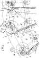
- FIG. 1 shows a device for carrying out the method according to the invention for collecting or collating and then stapling printed products having an overfold, which, prior to stapling, comprises a plurality of receiving rungs 2 which form an endless conveyor device 1 and are arranged at intervals one behind the other transversely to the direction of transport and spread to astride-type Hang up to be fed.
- the receiving rungs 2 are fastened at regular intervals between chain-like links of two parallel, endless traction elements 3 which rotate around two spaced axes. The loading of the receiving rungs 2 follows from above on the upper run of the conveyor 1.
- the printed sheets are fed individually from the side or above with the fold ahead, approximately vertically to the conveying direction, arranged receiving pockets 4, which are driven about an approximately horizontal axis and in the same direction above the conveying device 1, the printed sheets being advanced with the overlap due to the circular motion offset in the receiving pockets at an outer stop 5 and then grasped at the overlap or removed from the receiving pocket 4, and during the conveying further spread their side parts and on an associated rung 2 of the conveyor 1 are discontinued.
- the arrows directed from the outside onto the circumference of the conveying element 11 indicate possibilities of the loading points.
- the receiving pockets are closed after loading.
- the subsequent removal of the printed sheets 6 from the receiving pockets 4 can take place at the earliest when they have reached an outer stop 5 with their overlap.
- a plurality of receiving pockets 4 are arranged above the conveying device 1 described on the circumference between two approximately circular hub disks 9 of an axis of rotation 10 of a conveying element 11 parallel to the receiving rungs 2.
- the receiving pockets 4 extend to a width which is determined by the distance between the hub disks 9.
- the receiving pockets 4, which are oriented approximately radially to the axis of rotation 10, are provided with an angled leg 13, which forms the pocket bottom or an inner stop 15, of one stationary side wall 14 of a receiving pocket 4.
- this stationary side wall 14 is arranged in the region of the conveying member 11 which is effective for conveying, below a movable side wall 16 belonging to the same receiving pocket 4.
- This side wall 16 which can be pivoted about a pivot axis 17 parallel to the axis of rotation 10 in the open and closed positions, has a control lever 18 which projects approximately perpendicularly in the region of the pivot axis 17, the free end of which controls the opening movement of the movable side wall 16 against a stationary control track 19 provided for this purpose the closed position is achieved by a spring acting on the movable side wall 16.
- the distance between the two side walls 14, 16 in the closed state of the receiving pocket 4 can be determined by a device provided for this purpose.
- the receiving pocket 4 can remain in its closed position until it is loaded further, or after a printed sheet 6 with both side parts has reached the position of the receiving rung 2 assigned to it, can be opened again for a short time.
- the receiving pockets 4 are closed approximately at the level of a horizontal plane through the axis of rotation 10.
- the closing of the receiving pockets 4 is to be carried out as soon as possible after the loading, especially since additional air penetrates into the opened receiving pocket 4 due to a certain fan action of the conveying element 11, which could apply the printing sheet 6 to the adjacent movable side wall 16 or keep it in a state of suspension, so that one Delay in shifting the printed sheets to the outer stop 5 occurs.
- the control track 19 is designed to be adjustable and lockable in a manner adapted to the loading point in the vicinity of the axis of rotation 10.
- the preparation of the printed sheets 6 in the receiving pockets 4 could be carried out in an analogous manner even with the stationary side wall 16 trailing in the direction of rotation.
- a removal device 20 connects to the outer free end of the stationary side wall 14, each of which is assigned to a receiving pocket 4 is.
- This removal device 20 consists of a drive shaft 21 arranged parallel to the axis of rotation 10 of the conveying member 11 between the hub disks 9, on which a plurality of disks 22 fastened at intervals next to one another are provided, which are distributed over the width for the supports to be removed from the receiving pockets 4 Sheet 6 forms.
- the individual disks 22 are provided on the circumference with a recess 23 which has a bearing surface 24 which is aligned with the stationary side wall 14 of the receiving pockets 4.
- the printed sheet 6 lies with its overlap 7 facing the outer stop 5 on the support surface 24 and can be gripped from there by means of a clamping device 25.
- This clamping device 25 forms with the support surface 24 a pair of clamping pliers 26 which can be opened by a stationary control member 27 by means of lever 36 and closed by spring force.
- the clamping device 25 is designed like a lever and is pivotably mounted on the disks 22. The clamping end of the clamping device 25 is located - as shown in FIG.
- the clamping tongs 26 open with the aid of a further control disk 35 which acts positively on the clamping device 25 and which is on the inside of a hub disk 9 - preferably on the opposite one Side or opposite hub disc 9 of the lever 35 - is fastened and takes place in cooperation with the rotational movement of the drive shaft 21, by lifting the clamping device 25 from the support surface 24.
- Another lever 37 provides for the transmission of the irregularity of the control disk 35.
- a lever gear 29 influenced by a stationary control curve 28 is used as a means for this purpose, the control curve 28 at least having a length that is necessary to completely remove a printed sheet 6 via the disks 22 from the receiving pockets 4.
- the lever mechanism 29 consists of a drive lever 30 guided in the control cam 28 and a toothed segment 32 fastened with the latter to a common axis 31, which meshes with a toothed wheel 33 on the drive shaft 21 of the removal device 20.
- a plurality of counter-rollers 34 are mounted which can be freely rotated about an axis parallel to the drive shaft 21 and which, with the receiving pocket 4 closed, has the circumference are spaced apart from the support surface 24 and exert a certain pressure on the periphery of the disks 22 when the printed sheet 6 is removed after it has run up on the circumference.
- the return movement of the removal device 20 is initiated after the removal has taken place with the receiving pockets 4 open, so that the counter roller 34 cannot be damaged by the rear edge of the recess 23.
Landscapes
- Engineering & Computer Science (AREA)
- Mechanical Engineering (AREA)
- Pile Receivers (AREA)
- Discharge By Other Means (AREA)
- Feeding Of Articles By Means Other Than Belts Or Rollers (AREA)
- Collation Of Sheets And Webs (AREA)
Applications Claiming Priority (2)
| Application Number | Priority Date | Filing Date | Title |
|---|---|---|---|
| CH378191 | 1991-12-19 | ||
| CH3781/91 | 1991-12-19 |
Publications (3)
| Publication Number | Publication Date |
|---|---|
| EP0551055A2 true EP0551055A2 (fr) | 1993-07-14 |
| EP0551055A3 EP0551055A3 (en) | 1993-09-01 |
| EP0551055B1 EP0551055B1 (fr) | 1996-08-28 |
Family
ID=4263349
Family Applications (1)
| Application Number | Title | Priority Date | Filing Date |
|---|---|---|---|
| EP92810997A Expired - Lifetime EP0551055B1 (fr) | 1991-12-19 | 1992-12-14 | Procédé et dispositif pour assembler des imprimés |
Country Status (4)
| Country | Link |
|---|---|
| US (1) | US5277413A (fr) |
| EP (1) | EP0551055B1 (fr) |
| JP (1) | JPH05238630A (fr) |
| DE (1) | DE59207003D1 (fr) |
Cited By (3)
| Publication number | Priority date | Publication date | Assignee | Title |
|---|---|---|---|---|
| EP0819641A1 (fr) * | 1996-07-19 | 1998-01-21 | Grapha-Holding Ag | Dispositif pour traiter des feuilles imprimées pliées |
| US5887532A (en) * | 1996-09-25 | 1999-03-30 | Grapha-Holding Ag | Method and apparatus for manufacturing book blocks |
| EP1016606A1 (fr) * | 1998-12-28 | 2000-07-05 | Grapha-Holding Ag | Margeur |
Families Citing this family (10)
| Publication number | Priority date | Publication date | Assignee | Title |
|---|---|---|---|---|
| ES2101889T3 (es) * | 1992-04-06 | 1997-07-16 | Ferag Ag | Procedimiento y dispositivo para abrir productos impresos plegados. |
| US5452886A (en) * | 1993-08-09 | 1995-09-26 | Heidelberger Druckmaschinen Ag | Device for slowing down signatures in a folding machine |
| US5794929A (en) * | 1993-08-09 | 1998-08-18 | Heidelberger Druckmaschinen Ag | Variable velocity profile decelleration device |
| CH688375A5 (de) * | 1994-05-31 | 1997-08-29 | Ferag Ag | Einrichtung zum Verarbeiten von Druckereiprodukten. |
| DE19527264A1 (de) * | 1995-07-26 | 1997-01-30 | Heidelberger Druckmasch Ag | Druckmaschine mit geradliniger Substratführung und Wendeeinrichtungen dafür |
| US5758871A (en) * | 1996-09-25 | 1998-06-02 | Heidelberg Finishing Systems, Inc. | Signature collating apparatus |
| US6131904A (en) * | 1998-09-01 | 2000-10-17 | Goss Graphic Systems, Inc. | Stripping mechanism for a delivery fly assembly |
| EP1234791B1 (fr) | 2001-02-19 | 2004-10-06 | Grapha-Holding AG | Dispositif de prélèvement et de transmission de produits imprimés |
| US9022715B2 (en) * | 2012-09-18 | 2015-05-05 | Applied Materials, Inc. | Load lock chamber designs for high-throughput processing system |
| CN114210572B (zh) * | 2021-12-14 | 2023-03-21 | 东北大学秦皇岛分校 | 一种电子商务物流分拣导向装置 |
Family Cites Families (14)
| Publication number | Priority date | Publication date | Assignee | Title |
|---|---|---|---|---|
| DE516168C (de) * | 1928-03-21 | 1931-01-24 | Burgerhout S Machf & Scheepswe | Beilageneinsteckmaschine |
| US2381546A (en) * | 1943-07-26 | 1945-08-07 | Ncr Co | Accounting machine |
| US3481594A (en) * | 1967-07-10 | 1969-12-02 | Chicago Machinery Lab Inc | Signature feeding apparatus |
| CH594553A5 (fr) * | 1976-02-19 | 1978-01-13 | Grapha Holding Ag | |
| CH644814A5 (de) * | 1980-01-08 | 1984-08-31 | Ferag Ag | Verfahren und vorrichtung zum oeffnen von gefalteten, gebundenen oder gehefteten mehrblaettrigen erzeugnissen, insbesondere druckprodukten. |
| CH652103A5 (de) * | 1981-09-22 | 1985-10-31 | Grapha Holding Ag | Anleger fuer falzbogen. |
| CH656863A5 (de) * | 1982-05-05 | 1986-07-31 | Grapha Holding Ag | Vorrichtung zum oeffnen von aus mehreren lagen bestehenden falzbogen. |
| DE3362515D1 (en) * | 1982-06-01 | 1986-04-17 | Ferag Ag | Device for collecting folded printing sheets |
| CH665411A5 (de) * | 1985-02-07 | 1988-05-13 | Grapha Holding Ag | Zusammentragmaschine. |
| CH667621A5 (de) * | 1985-06-04 | 1988-10-31 | Grapha Holding Ag | Sammelhefter. |
| US4901996A (en) * | 1986-11-10 | 1990-02-20 | Am International Incorporated | Apparatus and method for feeding sheet material from a stack for a collating conveyor |
| US5046711A (en) * | 1988-01-29 | 1991-09-10 | Hall Processing Systems | High speed drum type processing apparatus |
| CH676841A5 (fr) * | 1989-02-03 | 1991-03-15 | Grapha Holding Ag | |
| US4989850A (en) * | 1989-03-30 | 1991-02-05 | Weller Ronald W | Signature machines |
-
1992
- 1992-12-10 US US07/988,458 patent/US5277413A/en not_active Expired - Lifetime
- 1992-12-14 DE DE59207003T patent/DE59207003D1/de not_active Expired - Lifetime
- 1992-12-14 EP EP92810997A patent/EP0551055B1/fr not_active Expired - Lifetime
- 1992-12-18 JP JP4339326A patent/JPH05238630A/ja not_active Withdrawn
Cited By (4)
| Publication number | Priority date | Publication date | Assignee | Title |
|---|---|---|---|---|
| EP0819641A1 (fr) * | 1996-07-19 | 1998-01-21 | Grapha-Holding Ag | Dispositif pour traiter des feuilles imprimées pliées |
| US5975182A (en) * | 1996-07-19 | 1999-11-02 | Grapha-Holding Ag | Apparatus for processing folded printed sheets |
| US5887532A (en) * | 1996-09-25 | 1999-03-30 | Grapha-Holding Ag | Method and apparatus for manufacturing book blocks |
| EP1016606A1 (fr) * | 1998-12-28 | 2000-07-05 | Grapha-Holding Ag | Margeur |
Also Published As
| Publication number | Publication date |
|---|---|
| JPH05238630A (ja) | 1993-09-17 |
| EP0551055A3 (en) | 1993-09-01 |
| EP0551055B1 (fr) | 1996-08-28 |
| US5277413A (en) | 1994-01-11 |
| DE59207003D1 (de) | 1996-10-02 |
Similar Documents
| Publication | Publication Date | Title |
|---|---|---|
| DE2732591C2 (de) | Einrichtung zum Abbauen eines Stapels von biegsamen Flächengebilden | |
| EP0208081B1 (fr) | Procédé et dispositif d'ouverture pour imprimés pliés de manière excentrée | |
| DE19523164A1 (de) | Flexibles Fördersystem | |
| DE2348320B2 (de) | Vorrichtung zum stapelweisen Ablegen einzelner gleichlanger Bogen | |
| EP0551055B1 (fr) | Procédé et dispositif pour assembler des imprimés | |
| EP0675005A1 (fr) | Dispositif pour la reliure adhésive de produits imprimés | |
| CH649972A5 (de) | Vorrichtung zum uebereinanderlegen von einzelnen flaechigen erzeugnissen, insbesondere druckprodukten. | |
| EP0606550A1 (fr) | Dispositif pour transporter les objets plats à un dispositif de traitement de produit imprimé | |
| EP0600216B1 (fr) | Procédé et dispositif pour ouvrir des produits d'imprimerie pliés | |
| DE3603285A1 (de) | Zusammentragmaschine | |
| DE3621822C2 (fr) | ||
| EP1351873B1 (fr) | Procede de traitement de produits d'imprimerie | |
| EP0965547B1 (fr) | Dispositif pour traiter des produits flexibles et plats | |
| EP0210494B1 (fr) | Dispositif de rassemblement pour feuilles pliées | |
| EP3115325B1 (fr) | Dispositif et procédé pour la formation d'une pile de compositions de produits d'imprimerie publicitaires | |
| EP0242702A1 (fr) | Procédé et dispositif pour tourner des objets plats | |
| EP0771675A1 (fr) | Dispositif pour enlever des produits imprimés d'un transporteur en forme de selle | |
| EP2100839B1 (fr) | Dispositif de transport pour le prèlévement et la transmission de produits imprimés | |
| EP1253098A1 (fr) | Appareil pour la manutention des produits imprimés alimentés vers un dispositif d'empilage | |
| EP0967164B1 (fr) | Méthode et dispositif pour alimenter des feuilles imprimées et pliées à cheval sur une section d'assemblage | |
| EP0970820B1 (fr) | Dispositif de transport | |
| DE3330681A1 (de) | Verfahren zum schnellen zufuehren und transportieren von blattfoermigen papiererzeugnissen und vorrichtung zur durchfuehrung des verfahrens | |
| EP0518064B1 (fr) | Procédé et appareil pour la manutention de produits imprimés | |
| EP2035308B1 (fr) | Dispositif pour séparer différents objets plats d'une pile et pour évacuer les objets séparés | |
| CH690914A5 (de) | Vorrichtung zum Ueberführen von Druckbogen auf eine umlaufende Fördereinrichtung. |
Legal Events
| Date | Code | Title | Description |
|---|---|---|---|
| PUAI | Public reference made under article 153(3) epc to a published international application that has entered the european phase |
Free format text: ORIGINAL CODE: 0009012 |
|
| PUAL | Search report despatched |
Free format text: ORIGINAL CODE: 0009013 |
|
| AK | Designated contracting states |
Kind code of ref document: A2 Designated state(s): CH DE FR GB IT LI |
|
| AK | Designated contracting states |
Kind code of ref document: A3 Designated state(s): CH DE FR GB IT LI |
|
| 17P | Request for examination filed |
Effective date: 19931015 |
|
| 17Q | First examination report despatched |
Effective date: 19941215 |
|
| GRAH | Despatch of communication of intention to grant a patent |
Free format text: ORIGINAL CODE: EPIDOS IGRA |
|
| GRAH | Despatch of communication of intention to grant a patent |
Free format text: ORIGINAL CODE: EPIDOS IGRA |
|
| GRAH | Despatch of communication of intention to grant a patent |
Free format text: ORIGINAL CODE: EPIDOS IGRA |
|
| GRAA | (expected) grant |
Free format text: ORIGINAL CODE: 0009210 |
|
| AK | Designated contracting states |
Kind code of ref document: B1 Designated state(s): CH DE FR GB IT LI |
|
| PG25 | Lapsed in a contracting state [announced via postgrant information from national office to epo] |
Ref country code: IT Free format text: LAPSE BECAUSE OF FAILURE TO SUBMIT A TRANSLATION OF THE DESCRIPTION OR TO PAY THE FEE WITHIN THE PRESCRIBED TIME-LIMIT;WARNING: LAPSES OF ITALIAN PATENTS WITH EFFECTIVE DATE BEFORE 2007 MAY HAVE OCCURRED AT ANY TIME BEFORE 2007. THE CORRECT EFFECTIVE DATE MAY BE DIFFERENT FROM THE ONE RECORDED. Effective date: 19960828 Ref country code: GB Effective date: 19960828 Ref country code: FR Effective date: 19960828 |
|
| REF | Corresponds to: |
Ref document number: 59207003 Country of ref document: DE Date of ref document: 19961002 |
|
| EN | Fr: translation not filed | ||
| GBV | Gb: ep patent (uk) treated as always having been void in accordance with gb section 77(7)/1977 [no translation filed] |
Effective date: 19960828 |
|
| PLBE | No opposition filed within time limit |
Free format text: ORIGINAL CODE: 0009261 |
|
| 26N | No opposition filed | ||
| PGFP | Annual fee paid to national office [announced via postgrant information from national office to epo] |
Ref country code: DE Payment date: 20091215 Year of fee payment: 18 |
|
| REG | Reference to a national code |
Ref country code: DE Ref legal event code: R119 Ref document number: 59207003 Country of ref document: DE Effective date: 20110701 |
|
| PG25 | Lapsed in a contracting state [announced via postgrant information from national office to epo] |
Ref country code: DE Free format text: LAPSE BECAUSE OF NON-PAYMENT OF DUE FEES Effective date: 20110701 |
|
| PGFP | Annual fee paid to national office [announced via postgrant information from national office to epo] |
Ref country code: CH Payment date: 20120323 Year of fee payment: 20 |
|
| REG | Reference to a national code |
Ref country code: CH Ref legal event code: PL |