EP0313030A2 - Höhenregelungssystem in einer Kraftfahrzeugaufhängung für eine Regelung der Höhe und der Neigungsunterdrückung mit hohem Ansprechverhalten für die Regelung der Höhe - Google Patents
Höhenregelungssystem in einer Kraftfahrzeugaufhängung für eine Regelung der Höhe und der Neigungsunterdrückung mit hohem Ansprechverhalten für die Regelung der Höhe Download PDFInfo
- Publication number
- EP0313030A2 EP0313030A2 EP88117422A EP88117422A EP0313030A2 EP 0313030 A2 EP0313030 A2 EP 0313030A2 EP 88117422 A EP88117422 A EP 88117422A EP 88117422 A EP88117422 A EP 88117422A EP 0313030 A2 EP0313030 A2 EP 0313030A2
- Authority
- EP
- European Patent Office
- Prior art keywords
- height
- pressure
- sensor signal
- vehicle body
- vehicular
- Prior art date
- Legal status (The legal status is an assumption and is not a legal conclusion. Google has not performed a legal analysis and makes no representation as to the accuracy of the status listed.)
- Granted
Links
Images



Classifications
-
- B—PERFORMING OPERATIONS; TRANSPORTING
- B60—VEHICLES IN GENERAL
- B60G—VEHICLE SUSPENSION ARRANGEMENTS
- B60G17/00—Resilient suspensions having means for adjusting the spring or vibration-damper characteristics, for regulating the distance between a supporting surface and a sprung part of vehicle or for locking suspension during use to meet varying vehicular or surface conditions, e.g. due to speed or load
- B60G17/015—Resilient suspensions having means for adjusting the spring or vibration-damper characteristics, for regulating the distance between a supporting surface and a sprung part of vehicle or for locking suspension during use to meet varying vehicular or surface conditions, e.g. due to speed or load the regulating means comprising electric or electronic elements
- B60G17/017—Resilient suspensions having means for adjusting the spring or vibration-damper characteristics, for regulating the distance between a supporting surface and a sprung part of vehicle or for locking suspension during use to meet varying vehicular or surface conditions, e.g. due to speed or load the regulating means comprising electric or electronic elements characterised by their use when the vehicle is stationary, e.g. during loading, engine start-up or switch-off
-
- B—PERFORMING OPERATIONS; TRANSPORTING
- B60—VEHICLES IN GENERAL
- B60G—VEHICLE SUSPENSION ARRANGEMENTS
- B60G2202/00—Indexing codes relating to the type of spring, damper or actuator
- B60G2202/10—Type of spring
- B60G2202/15—Fluid spring
- B60G2202/152—Pneumatic spring
-
- B—PERFORMING OPERATIONS; TRANSPORTING
- B60—VEHICLES IN GENERAL
- B60G—VEHICLE SUSPENSION ARRANGEMENTS
- B60G2300/00—Indexing codes relating to the type of vehicle
- B60G2300/04—Trailers
-
- B—PERFORMING OPERATIONS; TRANSPORTING
- B60—VEHICLES IN GENERAL
- B60G—VEHICLE SUSPENSION ARRANGEMENTS
- B60G2400/00—Indexing codes relating to detected, measured or calculated conditions or factors
- B60G2400/10—Acceleration; Deceleration
- B60G2400/102—Acceleration; Deceleration vertical
-
- B—PERFORMING OPERATIONS; TRANSPORTING
- B60—VEHICLES IN GENERAL
- B60G—VEHICLE SUSPENSION ARRANGEMENTS
- B60G2400/00—Indexing codes relating to detected, measured or calculated conditions or factors
- B60G2400/10—Acceleration; Deceleration
- B60G2400/104—Acceleration; Deceleration lateral or transversal with regard to vehicle
-
- B—PERFORMING OPERATIONS; TRANSPORTING
- B60—VEHICLES IN GENERAL
- B60G—VEHICLE SUSPENSION ARRANGEMENTS
- B60G2400/00—Indexing codes relating to detected, measured or calculated conditions or factors
- B60G2400/10—Acceleration; Deceleration
- B60G2400/106—Acceleration; Deceleration longitudinal with regard to vehicle, e.g. braking
-
- B—PERFORMING OPERATIONS; TRANSPORTING
- B60—VEHICLES IN GENERAL
- B60G—VEHICLE SUSPENSION ARRANGEMENTS
- B60G2400/00—Indexing codes relating to detected, measured or calculated conditions or factors
- B60G2400/20—Speed
- B60G2400/204—Vehicle speed
-
- B—PERFORMING OPERATIONS; TRANSPORTING
- B60—VEHICLES IN GENERAL
- B60G—VEHICLE SUSPENSION ARRANGEMENTS
- B60G2400/00—Indexing codes relating to detected, measured or calculated conditions or factors
- B60G2400/25—Stroke; Height; Displacement
- B60G2400/252—Stroke; Height; Displacement vertical
-
- B—PERFORMING OPERATIONS; TRANSPORTING
- B60—VEHICLES IN GENERAL
- B60G—VEHICLE SUSPENSION ARRANGEMENTS
- B60G2400/00—Indexing codes relating to detected, measured or calculated conditions or factors
- B60G2400/30—Propulsion unit conditions
- B60G2400/35—Position of fuel or air injector
-
- B—PERFORMING OPERATIONS; TRANSPORTING
- B60—VEHICLES IN GENERAL
- B60G—VEHICLE SUSPENSION ARRANGEMENTS
- B60G2400/00—Indexing codes relating to detected, measured or calculated conditions or factors
- B60G2400/40—Steering conditions
- B60G2400/41—Steering angle
-
- B—PERFORMING OPERATIONS; TRANSPORTING
- B60—VEHICLES IN GENERAL
- B60G—VEHICLE SUSPENSION ARRANGEMENTS
- B60G2400/00—Indexing codes relating to detected, measured or calculated conditions or factors
- B60G2400/50—Pressure
-
- B—PERFORMING OPERATIONS; TRANSPORTING
- B60—VEHICLES IN GENERAL
- B60G—VEHICLE SUSPENSION ARRANGEMENTS
- B60G2400/00—Indexing codes relating to detected, measured or calculated conditions or factors
- B60G2400/60—Load
- B60G2400/62—Seat occupation; Passenger presence
-
- B—PERFORMING OPERATIONS; TRANSPORTING
- B60—VEHICLES IN GENERAL
- B60G—VEHICLE SUSPENSION ARRANGEMENTS
- B60G2401/00—Indexing codes relating to the type of sensors based on the principle of their operation
- B60G2401/12—Strain gauge
-
- B—PERFORMING OPERATIONS; TRANSPORTING
- B60—VEHICLES IN GENERAL
- B60G—VEHICLE SUSPENSION ARRANGEMENTS
- B60G2401/00—Indexing codes relating to the type of sensors based on the principle of their operation
- B60G2401/14—Photo or light sensitive means, e.g. Infrared
-
- B—PERFORMING OPERATIONS; TRANSPORTING
- B60—VEHICLES IN GENERAL
- B60G—VEHICLE SUSPENSION ARRANGEMENTS
- B60G2401/00—Indexing codes relating to the type of sensors based on the principle of their operation
- B60G2401/15—Doppler effect
-
- B—PERFORMING OPERATIONS; TRANSPORTING
- B60—VEHICLES IN GENERAL
- B60G—VEHICLE SUSPENSION ARRANGEMENTS
- B60G2401/00—Indexing codes relating to the type of sensors based on the principle of their operation
- B60G2401/17—Magnetic/Electromagnetic
- B60G2401/176—Radio or audio sensitive means, e.g. Ultrasonic
-
- B—PERFORMING OPERATIONS; TRANSPORTING
- B60—VEHICLES IN GENERAL
- B60G—VEHICLE SUSPENSION ARRANGEMENTS
- B60G2500/00—Indexing codes relating to the regulated action or device
- B60G2500/30—Height or ground clearance
-
- B—PERFORMING OPERATIONS; TRANSPORTING
- B60—VEHICLES IN GENERAL
- B60G—VEHICLE SUSPENSION ARRANGEMENTS
- B60G2600/00—Indexing codes relating to particular elements, systems or processes used on suspension systems or suspension control systems
- B60G2600/22—Magnetic elements
-
- B—PERFORMING OPERATIONS; TRANSPORTING
- B60—VEHICLES IN GENERAL
- B60G—VEHICLE SUSPENSION ARRANGEMENTS
- B60G2800/00—Indexing codes relating to the type of movement or to the condition of the vehicle and to the end result to be achieved by the control action
- B60G2800/01—Attitude or posture control
- B60G2800/014—Pitch; Nose dive
-
- B—PERFORMING OPERATIONS; TRANSPORTING
- B60—VEHICLES IN GENERAL
- B60G—VEHICLE SUSPENSION ARRANGEMENTS
- B60G2800/00—Indexing codes relating to the type of movement or to the condition of the vehicle and to the end result to be achieved by the control action
- B60G2800/22—Braking, stopping
-
- Y—GENERAL TAGGING OF NEW TECHNOLOGICAL DEVELOPMENTS; GENERAL TAGGING OF CROSS-SECTIONAL TECHNOLOGIES SPANNING OVER SEVERAL SECTIONS OF THE IPC; TECHNICAL SUBJECTS COVERED BY FORMER USPC CROSS-REFERENCE ART COLLECTIONS [XRACs] AND DIGESTS
- Y10—TECHNICAL SUBJECTS COVERED BY FORMER USPC
- Y10S—TECHNICAL SUBJECTS COVERED BY FORMER USPC CROSS-REFERENCE ART COLLECTIONS [XRACs] AND DIGESTS
- Y10S280/00—Land vehicles
- Y10S280/01—Load responsive, leveling of vehicle
Definitions
- the present invention relates generally to a vehicular height control system for an automotive suspension system. More specifically, the invention relates to an automotive height control system which is designed for performing a vehicular attitude control for suppressing an attitude change of a vehicular body and a height regulating control for maintaining a vehicular height within a predetermined height range. Further particularly, the invention relates to an automotive height control system which is provided with improved response characteristics in a height adjustment in response to a vehicular body displacement out of the target height range.
- Conventional automotive height control systems are provided with pneumatic chambers of variable pneumatic pressure for adjusting a pneumatic spring force to maintain the vehicular height at a predetermined height range.
- some systems are associated with variable damping force suspension systems which are of variable suspension characteristic for absorbing road shocks and for suppressing vehicular attitude changes.
- the height adjustment tends to be disabled in response to the attitude change because this attitude change may cause a temporary vehicular height variation which makes it impossible to obtain precise vehicular height data. It is a normal suspension procedure to give a higher priority for the attitude change suppressing operation than the height regulating operation so that the height adjustment is performed after the vehicular attitude is stabilized. This clearly degrades the response characteristics of the height regulating operation in response to the vehicular height variation due to a change of load, such as upon getting in or getting out of a passenger or passengers because the stability of the vehicular attitude has to be confirmed in advance of the performing height regulating operation.
- a height control system detects the occurrence of a vehicular load change, such as boarding and unboarding of passenger or passengers.
- the system also detects a variation of a vehicular height output of a predetermined range.
- the system becomes active to temporarily adjust the vehicular height according to a preset schedule and maintains the vehicular height at an adjusted position for a given period of time.
- the boarding and unboarding is practically distinguished for determining an adjusting direction of the vehicular height between UP direction and DOWN direction. Furthermore, in the preferred system, the height adjustment is normally performed during the stable condition of the vehicular attitude. However, when both the occurrence of the load change and the vehicular height variation output of the predetermined range are simultaneously detected, a height control is performed irrespective of the vehicular attitude change.
- an automotive height control system comprises: a suspension mechanism interposed between a vehicle body and a suspension member which rotatably supports a vehicular wheel and including a pressure chamber with a variable pressure of a pressure medium therewithin for adjusing a relative distance between the vehicle body and the suspension member; a pressure source circuit connected to the pressure chamber of the suspension mechanism for increasing the pressure of the pressure medium within the pressure chamber in a first mode for increasing the relative distance between the vehicle body and the suspension member, for decreasing the pressure of the pressure medium within the pressure chamber in a second mode for decreasing the relative distance between the vehicle body and the suspension member and for maintaining the pressure of the pressure medium within the pressure chamber constant in a third mode, whereby the pressure source circuit is normally operating in the third mode; a first sensor means for monitoring a vehicle body height level to produce a first sensor signal indicative of the vehicle body height level; a second sensor means for monitoring a vehicle body attitude change to produce a second sensor signal indicative of the magnitude of the vehicle body attitude change: a third sensor means for detecting a
- an automotive height control system comprises: a suspension mechanism interposed between a vehicle body and a suspension member which rotatably supports a vehicular wheel and including a pressure chamber with a variable pressure of a pressure medium therewithin for adjusting a relative distance between the vehicle body and the suspension member; a pressure source circuit connected to the pressure chamber of the suspension mechanism for increasing the pressure of the pressure medium within the pressure chamber in a first mode for increasing the relative distance between the vehicle body and the suspension member, for decreasing the pressure of the pressure medium within the pressure chamber in a second mode for decreasing the relative distance between the vehicle body and the suspension member and for maintaining the pressure of the pressure medium within the pressure chamber constant in a third mode, whereby the pressure source circuit is normally operating in the third mode; a first sensor means for monitoring a relative distance between the vehicle body and the suspension member to produce a first sensor signal indicative of the monitored relative distance; a second sensor means for monitoring a vehicle body attitude change to produce a second sensor signal indicative of the magnitude of the vehicle body attitude change; a third sensor means
- the third sensor means may comprise a door switch which turns ON in response to the opening of a door.
- the controlling means is active in the load change transition mode for a predetermined period of time as triggered by the third sensor signal. If necessary, the controlling means may derive the predetermined period on the basis of a difference between the first sensor signal value and a criterion defining the predetermined second height range.
- the preferred embodiment of a vehicular height control system has a pneumatic cylinder 2 which is disposed between a vehicular body 1 and a suspension member 3 which rotatably supports a road wheel.
- the pneumatic cylinder 2 has a pneumatic chamber 2a connected to a pneumatic pressure source unit 5 which includes a compressor 5a and a reservoir tank 5b, via a pressure control valve 4. Therefore, by the operation of the pressure control valve 4, pneumatic pressure in the pneumatic pressure chamber 2a is adjusted so as to expand the distance between the vehicular body 1 and the suspension member 3 by increasing the pneumatic pressure and to decrease the distance by decreasing the pneumatic pressure.
- the pressure control valve 4 may be designed as a three way valve which is variable between an UP mode position in which the pneumatic pressure chamber 2a is communicated with the pressure source unit 5 to introduce the pneumatic pressure for increasing the pneumatic pressure in the pneumatic pressure chamber 2a and a DOWN mode position, in which the pneumatic pressure chamber 2a is exposed to atmosphere to vent the pressurized air or gas for decreasing the pneumatic pressure in the pneumatic pressure chamber 2a, and a SHUT position, in which the pneumatic chamber 2a is closed to maintain the pneumatic pressure substantially constant.
- the control unit 7 generally comprises CPU 7a, a memory 7b including RAM and ROM, a timer 7c and an input/output interface 7d.
- the control unit 7 is connected to a vehicular height sensor 6.
- the vehicular height sensor 6 may comprise a stroke sensor disposed between the vehicular body 1 and the suspension member 3, as shown in Fig. 1.
- the stroke sensor may comprise an optical sensor, a magnetic sensor, a strain gauge and so forth.
- the vehicular height sensor may comprise a sensor which monitors the vehicular height from a road surface.
- Such a vehicular height sensor may comprise a doppler sensor, an ultrasonic sensor and so forth.
- the vehicular height sensor 6 produces a vehicular height indication signal.
- the control unit 7 is also connected to a plurality of door open detector switches 9a, 9b, 9c and 9d, each of which detects an open condition of an associated one of a vehicular door to produce a HIGH level door condition indication signal.
- the control unit 7 is further connected to vehicular attitude monitoring sensors which are generally represented by the reference numeral 8.
- the attitude monitoring sensors 8 may be constituted of a rolling sensor, a pitching sensor and the like.
- the rolling sensor may comprise a vehicle speed sensor and a steering angle sensor for detecting the magnitude of rolling.
- the rolling sensor may also comprise a lateral acceleration sensor.
- the pitching sensor may comprise a braking state and thereby detecting a vehicular decelerating condition, a longitudinal acceleration sensor, a fuel injection pulse sensor which counts the fuel injection pulses for detecting the acceleration and the deceleration of an automotive engine and thereby detecting the acceleration and the decelaration of the vehicle.
- vehicular attitude monitoring sensors 8 Since the kind of sensor or sensors for monitoring the vehicle driving parameter or parameters affecting the vehicle body attitude is not essential to the shown embodiment of the vehicular height control system, those sensors will be generally referred to as the vehicular attitude monitoring sensors 8.
- the sensor signals produced by the vehicular attitude monitoring sensors 8 and representative of the vehicular attitude will be hereafter referred to as vehicular attitude indication signals.
- the control unit 7 is further connected to a compressor driver circuit 11 and a pressure control valve driver circuit 10.
- the control unit 7 is further connected to a pressure sensor 12 for monitoring the pneumatic pressure in the reservoir tank 5b of the pressure source unit 5 to produce a pressure indication signal.
- the control unit 7 is responsive to the pressure indication signal value if it is smaller than or equal to a predetermined low pressure criterion to produce a compressor control signal.
- the compressor control signal is fed to the compressor driver circuit 11.
- the compressor driver circuit 11 is responsive to the compressor control signal to drive the compressor 5a to incrase the pressure in the reservoir tank 5b.
- the shown embodiment is designed to drive the compressor 5a when the pneumatic pressure in the reservoir tank 5b becomes lower than or equal to the low pressure criterion. It is possible to drive the compressor 5a whenever the pressure control valve 4 is operated into the UP mode position. In such case, the pressure sensor 12 in the reservoir tank 5b is not necessary.
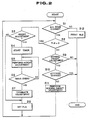
- Fig. 2 shows a height control program executed by the control unit 7 in the preferred embodiment of the height control system of Fig. 1.
- the door condition indication signal from the door open detector switches 9a, 9b, 9c and 9d are checked at a step S1.
- This stage is provided for detecting the opening of a door.
- the system recognizes that the load on the vehicle will be increased by boarding of one or more passengers at a first occurrence of a HIGH level door condition indication signal and that the load on the vehicle will be decreased by unboarding or getting off of one or more passengers at a second occurrence of the HIGH level door condition indication signal.
- step S1 If any one of the door condition indication signals of the door open detector switches 9a, 9b, 9c and 9d are detected at the step S1, the process goes to a step S12 to reset a load change transition indication flag FLG. Thereafter, process goes to END.
- the load change transition state indication flag FLG is checked at a step S2.
- the vehicular height indication signal value is then checked to detect the vehicular height level at a step S9. Namely, at the step S9, the vehicular height indication signal value is compared with an upper threshold value representative of an upper limit of a predetermined normal state height range and a lower threshold representative of a lower limit of the predetermined normal state vehicular height range.
- the aforementioned normal state height range is set in relation to a predetermined target height and defined by the aforementioned upper and lower limit with taking the target height as the center value.
- the process goes to END.
- the vehicular attitude indication signal is checked at a step S10.
- the vehicular attitude indication signal as checked at the step S10 indicates the vehicular attitude change
- the process goes END.
- the vehicular attitude indication signal as checked at the step S10 indicates that the vehicular attitude is unchanged the height adjustment is performed by supplying the height control signal to the pressure control valve driver circuit 10 at a step S11.
- the control signal serves as a DOWN command ordering a DOWN mode position of the pressure control valve 10.
- the control signal serves as an UP command ordering an UP mode position of the pressure control valve 10.
- the vehicular height indication signal value is compared with an upper criterion which defines an upper limit of a predetermined transition state height range and a lower criterion which defines a lower limit of the transition state height range.
- the transition state height range is broader than the normal state height range.
- the timer 7c is triggered to start the measurement of an elapsed time.
- the transition state height adjustment is performed at a step S5 to adjust the vehicular height within the transition state height range.
- the vehicular height is adjusted toward the upper or lower limit of the transition state height range. Namely, when the vehicular height is higher than the upper limit the control signal serving as the DOWN command is supplied to operate the pressure in the pneumatic chamber 2a. The DOWN mode ordering control signal is maintained until the vehicular height becomes lower than or equal to the upper limit of the transition state height range.
- the control signal serving as the UP command is produced to operate the pressure control valve 10 to the UP mode position.
- the pressure is increased by the pneumatic pressure source unit 5 to rise the vehicular height.
- the UP mode ordering control signal is terminated when the vehicular height increases across the lower limit of the transition state height range.
- the timer value of the timer 7c as triggered at the step S4 is checked at a step S6.
- the process returns to the step S5.
- the timer value becomes grater than or equal to the predetermined value as checked at the step S6
- the transition state height adjustment is terminated at a step S7 irrespective of the vehicular height position. Namely, when the time over is detected at the step S6, the transition state height adjustment is terminated even when the vehicular height is still out of the transition state height range.
- the load change transition indication flag FLG is set at a step S8 to indicate that the state of the height control is not in the load change transition state. Thereafter, the process returns to the step S1.
- the timer 7c is designed to detect the fixed transition state height adjustment period so that the transition state height adjustment is performed within the fixed period. However, it may be possible to vary the transition state height adjustment period so that the transition state height adjustment can be completed within the period of time while the transition state height adjustment is active.
- Fig. 3 shows a modification of the height control program of Fig. 2.
- the modified routine of Fig. 3 the feature of an adjustment of the transition state height adjustment period depending upon the height difference between the actual vehicular height and the upper or lower limit of the transition state height range is introduced.
- a step S21 is added between the steps S3 and S4.
- a height difference from an adjacent one of the upper and the lower limit of the transition state height range is derived.
- the timer set value which is representative of the transition state height adjustment period, is determined according to the characteristics shown in Fig. 4.
- the present invention has been disclosed in detail in terms of the preferred embodiment of the invention, the invention can be implemented in various ways.
- the shown embodiment employs pneumatic cylinders for adjusting the vehicular height
- hydraulic or hydropneumatic cylinders for adjusting the height level of the vehicular body.
- the pressure chamber in the hydraulic cylinder is to be connected to a hydraulic pressure source.
- the shown embodiment employs the vehicular height sensor for monitoring the vehicular height level
- a vertical acceleration sensor monitoring the vehicle body acceleration in a vertical direction can be employed in place of the vehicular height sensor for detecting a vertical displacement of the vehicular height.
- the vertical height position may be derived by integrating the vertical acceleration indication signal values.
Landscapes
- Engineering & Computer Science (AREA)
- Mechanical Engineering (AREA)
- Vehicle Body Suspensions (AREA)
Applications Claiming Priority (2)
| Application Number | Priority Date | Filing Date | Title |
|---|---|---|---|
| JP265153/87 | 1987-10-19 | ||
| JP62265153A JP2578836B2 (ja) | 1987-10-19 | 1987-10-19 | 自動車の車高調整装置 |
Publications (3)
| Publication Number | Publication Date |
|---|---|
| EP0313030A2 true EP0313030A2 (de) | 1989-04-26 |
| EP0313030A3 EP0313030A3 (en) | 1990-10-17 |
| EP0313030B1 EP0313030B1 (de) | 1993-03-31 |
Family
ID=17413365
Family Applications (1)
| Application Number | Title | Priority Date | Filing Date |
|---|---|---|---|
| EP88117422A Expired - Lifetime EP0313030B1 (de) | 1987-10-19 | 1988-10-19 | Höhenregelungssystem in einer Kraftfahrzeugaufhängung für eine Regelung der Höhe und der Neigungsunterdrückung mit hohem Ansprechverhalten für die Regelung der Höhe |
Country Status (4)
| Country | Link |
|---|---|
| US (1) | US4903209A (de) |
| EP (1) | EP0313030B1 (de) |
| JP (1) | JP2578836B2 (de) |
| DE (1) | DE3879866T2 (de) |
Cited By (5)
| Publication number | Priority date | Publication date | Assignee | Title |
|---|---|---|---|---|
| EP0449142A3 (en) * | 1990-03-23 | 1992-12-23 | Mazda Motor Corporation | Suspension system for automotive vehicle |
| EP0502184A4 (en) * | 1990-09-25 | 1993-06-09 | Monroe Auto Equipment Company | Shock absorber with sonar position sensor |
| CN1060440C (zh) * | 1996-07-04 | 2001-01-10 | 日野汽车工业株式会社 | 车高调节装置 |
| EP0925967A3 (de) * | 1997-12-26 | 2001-04-25 | Toyota Jidosha Kabushiki Kaisha | Vorrichtung zum Ermitteln eines Gefälles und zur Niveauregulierung eines Fahrzeugs und diese Vorrichtung benutzendes Verfahren |
| EP0945288A3 (de) * | 1998-03-27 | 2001-06-20 | DaimlerChrysler AG | Luftfederungsanlage für Fahrzeuge |
Families Citing this family (30)
| Publication number | Priority date | Publication date | Assignee | Title |
|---|---|---|---|---|
| DE68921590T2 (de) * | 1988-12-28 | 1995-07-27 | Aisin Seiki | Aktives hydraulisches Steuersystem, welches das Steuern der Lage eines hochbelasteten Fahrzeugs ermöglicht. |
| US5287277A (en) * | 1989-02-03 | 1994-02-15 | Fuji Jukogyo Kabushiki Kaisha | Method and apparatus for controlling height of a vehicle |
| EP0398158B1 (de) * | 1989-05-13 | 1993-08-25 | Toyota Jidosha Kabushiki Kaisha | Fahrzeughöhenregelvorrichtung, eingerichtet auch für den Betrieb nach dem Ausschalten des Zündschalters |
| US5113345A (en) * | 1989-05-29 | 1992-05-12 | Fuji Jukogyo Kabushiki Kaisha | System for controlling active suspensions of a vehicle |
| DE3918735A1 (de) * | 1989-06-08 | 1990-12-13 | Bosch Gmbh Robert | Verfahren und vorrichtung zur daempfung von bewegungsablaeufen |
| US5052713A (en) * | 1990-08-06 | 1991-10-01 | Lufkin Industries, Inc. | Vehicle suspension safety system |
| JP2541353B2 (ja) * | 1990-09-18 | 1996-10-09 | 三菱自動車工業株式会社 | 車両用アクティブサスペンション装置 |
| JPH05238224A (ja) * | 1992-03-03 | 1993-09-17 | Atsugi Unisia Corp | 車両懸架装置 |
| GB9213268D0 (en) * | 1992-06-23 | 1992-08-05 | Rover Group | A suspension system for a vehicle |
| US5430647A (en) * | 1992-12-07 | 1995-07-04 | Ford Motor Company | Method and apparatus for maintaining vehicular ride height |
| US6259982B1 (en) * | 1993-02-02 | 2001-07-10 | Trw Inc. | Method and apparatus for controlling an active suspension system |
| US5465209A (en) * | 1994-06-10 | 1995-11-07 | General Motors Corporation | Vehicle level control system |
| DE19539887B4 (de) * | 1995-10-26 | 2008-07-10 | Knorr-Bremse Systeme für Nutzfahrzeuge GmbH | Vorrichtung zur Regelung eines Fahrzeugaufbauniveaus |
| US6986519B2 (en) | 1997-01-31 | 2006-01-17 | Aloha, Llc | Low profile chassis and suspension |
| US6398251B1 (en) * | 1997-01-31 | 2002-06-04 | Dallas Smith Corporation | Axleless vehicle suspension system |
| US7559400B2 (en) | 1997-01-31 | 2009-07-14 | Aloha, Llc | Low profile chassis and suspension |
| AU8037800A (en) | 1999-09-01 | 2001-03-26 | Dallas Smith Corporation | Staggered independent suspension |
| DE10052888C1 (de) * | 2000-08-12 | 2001-10-18 | Freudenberg Carl Fa | Einrichtung zur Steuerung der Durchflussmenge an Druckflüssigkeit in einer Zuleitung für Fahrzeuge |
| PL1615787T3 (pl) * | 2003-04-17 | 2010-03-31 | Firestone Ind Products Co Llc | Sposób i układ do wyrównywania nieruchomego pojazdu względem sztucznego horyzontu |
| US8306696B2 (en) * | 2003-04-17 | 2012-11-06 | Driveright Holdings, Ltd. | Method and system for aligning a vehicle with an artificial horizon |
| WO2005039900A2 (en) | 2003-10-24 | 2005-05-06 | Aloha, Llc | Suspensions for low floor vehicles |
| US7744099B2 (en) * | 2004-11-04 | 2010-06-29 | Driveright Holdings, Ltd. | Method and system for adjusting a vehicle aligned with an artificial horizon |
| JP2006341665A (ja) * | 2005-06-07 | 2006-12-21 | Denso Corp | 車載機器制御システム |
| US7490836B2 (en) * | 2005-09-01 | 2009-02-17 | Cnh America Llc | Progressive control for a front suspended axle of a vehicle |
| US7938411B2 (en) * | 2007-09-21 | 2011-05-10 | Bendix Commercial Vehicle Systems, Llc | Axle air dump for multiple axle vehicles |
| US8155835B2 (en) * | 2008-02-21 | 2012-04-10 | Driveright Holdings, Ltd. | Vehicle chassis height adjustment method and system |
| CA2714255A1 (en) | 2009-09-01 | 2011-03-01 | Timbren Industries Inc. | Suspension mechanism |
| US20110093239A1 (en) * | 2009-10-21 | 2011-04-21 | Holbrook Gregory A | Vehicle weight sensing methods and systems |
| GB2511827B (en) * | 2013-03-14 | 2015-08-12 | Jaguar Land Rover Ltd | Control unit for a vehicle suspension |
| DE102016110854B4 (de) | 2016-06-14 | 2024-04-25 | Dr. Ing. H.C. F. Porsche Aktiengesellschaft | Verfahren zur Niveauregulierung eines Kraftfahrzeugs und Kraftfahrzeug mit einer Niveauregulierungsvorrichtung |
Family Cites Families (7)
| Publication number | Priority date | Publication date | Assignee | Title |
|---|---|---|---|---|
| JPS5849503A (ja) * | 1981-09-10 | 1983-03-23 | Aisin Seiki Co Ltd | 車高調整装置 |
| US4568096A (en) * | 1984-04-19 | 1986-02-04 | General Motors Corporation | Automatic vehicle level control |
| DE3667767D1 (de) * | 1985-02-06 | 1990-02-01 | Toyota Motor Co Ltd | Aktives fahrzeug-aufhaengungssystem mit eingebauten beschleunigungsmessern. |
| JPH075009B2 (ja) * | 1985-10-22 | 1995-01-25 | トヨタ自動車株式会社 | 車輌用車高調整装置 |
| US4761022A (en) * | 1986-03-08 | 1988-08-02 | Toyota Jidosha Kabushiki Kaisha | Suspension controller for improved turning |
| JPH0694253B2 (ja) * | 1986-03-17 | 1994-11-24 | トヨタ自動車株式会社 | 車輌用ロ−ル制御装置 |
| US4829436A (en) * | 1987-06-29 | 1989-05-09 | General Motors Corporation | Vehicle air suspension system with accurate side to side leveling |
-
1987
- 1987-10-19 JP JP62265153A patent/JP2578836B2/ja not_active Expired - Lifetime
-
1988
- 1988-10-17 US US07/258,731 patent/US4903209A/en not_active Expired - Fee Related
- 1988-10-19 EP EP88117422A patent/EP0313030B1/de not_active Expired - Lifetime
- 1988-10-19 DE DE88117422T patent/DE3879866T2/de not_active Expired - Fee Related
Cited By (5)
| Publication number | Priority date | Publication date | Assignee | Title |
|---|---|---|---|---|
| EP0449142A3 (en) * | 1990-03-23 | 1992-12-23 | Mazda Motor Corporation | Suspension system for automotive vehicle |
| EP0502184A4 (en) * | 1990-09-25 | 1993-06-09 | Monroe Auto Equipment Company | Shock absorber with sonar position sensor |
| CN1060440C (zh) * | 1996-07-04 | 2001-01-10 | 日野汽车工业株式会社 | 车高调节装置 |
| EP0925967A3 (de) * | 1997-12-26 | 2001-04-25 | Toyota Jidosha Kabushiki Kaisha | Vorrichtung zum Ermitteln eines Gefälles und zur Niveauregulierung eines Fahrzeugs und diese Vorrichtung benutzendes Verfahren |
| EP0945288A3 (de) * | 1998-03-27 | 2001-06-20 | DaimlerChrysler AG | Luftfederungsanlage für Fahrzeuge |
Also Published As
| Publication number | Publication date |
|---|---|
| DE3879866D1 (de) | 1993-05-06 |
| JPH01106720A (ja) | 1989-04-24 |
| JP2578836B2 (ja) | 1997-02-05 |
| US4903209A (en) | 1990-02-20 |
| DE3879866T2 (de) | 1993-10-14 |
| EP0313030A3 (en) | 1990-10-17 |
| EP0313030B1 (de) | 1993-03-31 |
Similar Documents
| Publication | Publication Date | Title |
|---|---|---|
| US4903209A (en) | Height control system in automotive suspension system performing attitude change suppressive control and height regulating control with high response characteristics in height adjustment | |
| US5487006A (en) | System for detecting road roughness for suspension control and automotive suspension control system utilizing thus detected road roughness as control parameter | |
| US4936604A (en) | Vehicular height control system for automotive suspension system with improved height control characteristics on undulated road and/or rough road | |
| US5072392A (en) | Suspension control system for automotive vehicle with feature of discrimination of vehicular driving condition on the basis of variation of lateral acceleration | |
| EP0318713B1 (de) | System zur Regelung einer Fahrzeugaufhängung | |
| US4948166A (en) | Vehicular height regulation system with variable sensitivity depending upon vehicle driving condition | |
| US5797111A (en) | Fuel flow controller | |
| US5141245A (en) | Apparatus for adjusting vehicle body height | |
| KR101118429B1 (ko) | 임계 주행 상황에서의 차량 틸팅 안정화를 위한 방법 및 주행 다이내믹 조절 시스템 | |
| EP0412530B1 (de) | Steuerverfahren eines aktiven Aufhängungssystems | |
| KR100222496B1 (ko) | 자동차의 헤드라이트 범위 조정장치 | |
| US5054813A (en) | Rolling suppressive control system for automotive suspension system with enhanced response characteristics | |
| US20020059023A1 (en) | Rolling control apparatus and method of vehicle | |
| US20070017727A1 (en) | Vehicle loading based vehicle dynamic and safety related characteristic adjusting system | |
| US5517847A (en) | Open compartment load leveling ride height control | |
| KR20010013131A (ko) | 차량의 안정화 방법 및 장치 | |
| US8209067B2 (en) | Height control device for vehicle | |
| KR101148267B1 (ko) | 레벨링 시스템을 구비한 차량에서 감쇠력을 조정하기 위한방법 | |
| EP0143983B1 (de) | System zum Regulieren der Fahrzeughöhe | |
| EP0393655B1 (de) | Höhenregulierung bei einem aktiven Federungssystem | |
| US6311112B1 (en) | Occupant restraint system and method having smart process initiation control | |
| US4664409A (en) | Vehicle shock absorber control system | |
| GB2144243A (en) | A vehicle height control system | |
| US6616150B2 (en) | Ride leveler system in vehicles | |
| KR970069430A (ko) | 자동차의 자동레벨링 조정장치 |
Legal Events
| Date | Code | Title | Description |
|---|---|---|---|
| PUAI | Public reference made under article 153(3) epc to a published international application that has entered the european phase |
Free format text: ORIGINAL CODE: 0009012 |
|
| 17P | Request for examination filed |
Effective date: 19881019 |
|
| AK | Designated contracting states |
Kind code of ref document: A2 Designated state(s): DE GB |
|
| PUAL | Search report despatched |
Free format text: ORIGINAL CODE: 0009013 |
|
| AK | Designated contracting states |
Kind code of ref document: A3 Designated state(s): DE GB |
|
| 17Q | First examination report despatched |
Effective date: 19910211 |
|
| GRAA | (expected) grant |
Free format text: ORIGINAL CODE: 0009210 |
|
| AK | Designated contracting states |
Kind code of ref document: B1 Designated state(s): DE GB |
|
| REF | Corresponds to: |
Ref document number: 3879866 Country of ref document: DE Date of ref document: 19930506 |
|
| PLBE | No opposition filed within time limit |
Free format text: ORIGINAL CODE: 0009261 |
|
| STAA | Information on the status of an ep patent application or granted ep patent |
Free format text: STATUS: NO OPPOSITION FILED WITHIN TIME LIMIT |
|
| 26N | No opposition filed | ||
| PGFP | Annual fee paid to national office [announced via postgrant information from national office to epo] |
Ref country code: GB Payment date: 19981023 Year of fee payment: 11 Ref country code: DE Payment date: 19981023 Year of fee payment: 11 |
|
| PG25 | Lapsed in a contracting state [announced via postgrant information from national office to epo] |
Ref country code: GB Free format text: LAPSE BECAUSE OF NON-PAYMENT OF DUE FEES Effective date: 19991019 |
|
| GBPC | Gb: european patent ceased through non-payment of renewal fee |
Effective date: 19991019 |
|
| PG25 | Lapsed in a contracting state [announced via postgrant information from national office to epo] |
Ref country code: DE Free format text: LAPSE BECAUSE OF NON-PAYMENT OF DUE FEES Effective date: 20000801 |