EP0313205A2 - Dispositif pour l'alignement de la tête d'impression et du chariot et mécanisme de verrouillage de l'interconnexion électronique - Google Patents
Dispositif pour l'alignement de la tête d'impression et du chariot et mécanisme de verrouillage de l'interconnexion électronique Download PDFInfo
- Publication number
- EP0313205A2 EP0313205A2 EP88308397A EP88308397A EP0313205A2 EP 0313205 A2 EP0313205 A2 EP 0313205A2 EP 88308397 A EP88308397 A EP 88308397A EP 88308397 A EP88308397 A EP 88308397A EP 0313205 A2 EP0313205 A2 EP 0313205A2
- Authority
- EP
- European Patent Office
- Prior art keywords
- cartridge
- carriage
- assembly
- printhead
- spring
- Prior art date
- Legal status (The legal status is an assumption and is not a legal conclusion. Google has not performed a legal analysis and makes no representation as to the accuracy of the status listed.)
- Granted
Links
- 230000007246 mechanism Effects 0.000 title description 3
- 238000007639 printing Methods 0.000 claims abstract description 8
- 229940090045 cartridge Drugs 0.000 claims description 126
- 210000005069 ears Anatomy 0.000 claims description 3
- 230000000007 visual effect Effects 0.000 claims description 3
- 230000000875 corresponding effect Effects 0.000 claims 4
- 238000010304 firing Methods 0.000 abstract description 3
- 230000002226 simultaneous effect Effects 0.000 abstract description 2
- 210000003811 finger Anatomy 0.000 description 6
- 210000003813 thumb Anatomy 0.000 description 3
- 230000009471 action Effects 0.000 description 2
- 210000005224 forefinger Anatomy 0.000 description 2
- 238000010438 heat treatment Methods 0.000 description 2
- 239000000463 material Substances 0.000 description 2
- 230000013011 mating Effects 0.000 description 2
- 230000004048 modification Effects 0.000 description 2
- 238000012986 modification Methods 0.000 description 2
- OKTJSMMVPCPJKN-UHFFFAOYSA-N Carbon Chemical compound [C] OKTJSMMVPCPJKN-UHFFFAOYSA-N 0.000 description 1
- 239000004721 Polyphenylene oxide Substances 0.000 description 1
- XUIMIQQOPSSXEZ-UHFFFAOYSA-N Silicon Chemical compound [Si] XUIMIQQOPSSXEZ-UHFFFAOYSA-N 0.000 description 1
- 230000001133 acceleration Effects 0.000 description 1
- 239000000853 adhesive Substances 0.000 description 1
- 230000001070 adhesive effect Effects 0.000 description 1
- 230000002457 bidirectional effect Effects 0.000 description 1
- 229910052799 carbon Inorganic materials 0.000 description 1
- 238000011109 contamination Methods 0.000 description 1
- 239000003989 dielectric material Substances 0.000 description 1
- 239000013536 elastomeric material Substances 0.000 description 1
- 238000005516 engineering process Methods 0.000 description 1
- 239000011521 glass Substances 0.000 description 1
- 239000003292 glue Substances 0.000 description 1
- 210000004247 hand Anatomy 0.000 description 1
- 238000007641 inkjet printing Methods 0.000 description 1
- 238000003780 insertion Methods 0.000 description 1
- 230000037431 insertion Effects 0.000 description 1
- 239000002184 metal Substances 0.000 description 1
- 239000004417 polycarbonate Substances 0.000 description 1
- 229920000515 polycarbonate Polymers 0.000 description 1
- 229940058401 polytetrafluoroethylene Drugs 0.000 description 1
- 229920001343 polytetrafluoroethylene Polymers 0.000 description 1
- 239000004810 polytetrafluoroethylene Substances 0.000 description 1
- -1 polytetrafluoroethylene Polymers 0.000 description 1
- 230000036316 preload Effects 0.000 description 1
- 230000035939 shock Effects 0.000 description 1
- 230000011664 signaling Effects 0.000 description 1
- 229910052710 silicon Inorganic materials 0.000 description 1
- 239000010703 silicon Substances 0.000 description 1
Images

Classifications
-
- B—PERFORMING OPERATIONS; TRANSPORTING
- B41—PRINTING; LINING MACHINES; TYPEWRITERS; STAMPS
- B41J—TYPEWRITERS; SELECTIVE PRINTING MECHANISMS, i.e. MECHANISMS PRINTING OTHERWISE THAN FROM A FORME; CORRECTION OF TYPOGRAPHICAL ERRORS
- B41J2/00—Typewriters or selective printing mechanisms characterised by the printing or marking process for which they are designed
- B41J2/005—Typewriters or selective printing mechanisms characterised by the printing or marking process for which they are designed characterised by bringing liquid or particles selectively into contact with a printing material
-
- B—PERFORMING OPERATIONS; TRANSPORTING
- B41—PRINTING; LINING MACHINES; TYPEWRITERS; STAMPS
- B41J—TYPEWRITERS; SELECTIVE PRINTING MECHANISMS, i.e. MECHANISMS PRINTING OTHERWISE THAN FROM A FORME; CORRECTION OF TYPOGRAPHICAL ERRORS
- B41J25/00—Actions or mechanisms not otherwise provided for
- B41J25/34—Bodily-changeable print heads or carriages
Definitions
- the present invention relates to ink-jet printers, and, more particularly, to alignment of the printhead and carriage and an electrical interconnect lock-in mechanism for controlling the printhead.
- a printhead In ink-jet printing technology, a printhead, comprising a plurality of nozzles in a nozzle plate, is fluidically associated with a reservoir of ink.
- the printhead is mounted on one end of a print cartridge and the reservoir is provided inside the cartridge.
- An interconnect means which carries electrical signals from a microprocessor in the printer to the printhead.
- these signals provide a current to resistors associated with the nozzles and thus control the heating of specific resistors, which in turn form droplets of ink.
- the droplets of ink are expelled through the nozzles toward a print medium, such as paper.
- the particular pattern of resistor heating controls the pattern of characters formed on the print medium.
- the print cartridge is supported in a carriage, which is adapted to move bidirectionally, normal to the movement of the print medium through the printer.
- the carriage movement is controlled by a motor and an associated belt drive, with the motor controlled by the microprocessor.
- a printhead cartridge and carriage assembly comprising:
- the cartridge has top, bottom, sides, front and rear surfaces and includes a printhead on the bottom surface, a contact on the back surface connected to the printhead, referencing pads on the side surfaces, and a lip on the back surface for accepting a snap spring for locking the cartridge in position in the carriage.
- the securing means includes the snap spring and means for receiving the referencing pads on the cartridge.
- the force loading means urge the interconnect means against the contact of the cartridge.
- the printhead cartridge/carriage assembly of the invention requries only one hand of the operator to both insert and lock the cartridge in position.
- the cartridge/carriage assembly provides simultaneous alignment of the nozzle plate in the X, Y, and Z directions
- contact between the printhead and the interconnect means is reliably made each time the cartridge is inserted and locked in position, thereby ensuring proper nozzle firing each time.
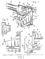
- FIG. 1 a print cartridge/carriage assembly, denoted generally at 10, is shown in FIG. 1.
- the assembly 10 comprises a carriage 12 in which a print cartridge 14 is depicted, locked into position.
- An interconnect strip 16 provides electrical signals from a microprocessor (not shown) to the cartridge 14, as discussed more fully below.
- the carriage 12 comprises a base support 18 and a chute 20 affixed thereto by fastening means 22.
- the carriage 12 advantageously comprises a glass-filled, carbon-filled, polytetrafluoroethylene-filled, silicon-filled polycarbonate.
- the interconnect strip 16 and a spring pad 24 are sandwiched by the support 18 and chute 20.
- the spring pad 24 comprises a resilient, elastomeric material and, as seen in FIG. 3, comprises a plurality of resilient bumps 26.
- the spring pad 24 is seated in a depression 25 (shown in FIG. 4) in the carriage base support 18, behind a portion of the interconnect strip 16, as described more fully below.
- the base support 18 and chute 20 are aligned in proper relationship by molded-in features such as pipe 27, which engage through corresponding openings in the interconnect strip 16 into opposed openings in the other member.
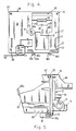
- the interconnect strip 16 comprises a strip of flexible dielectric material, carrying a plurality of electrically conducting lines 28, as seen more clearly in FIG. 8.
- the conducting lines 28 terminate in convex contact bumps or dimples 30, which are configured in a particular pattern.
- the bumps 26 on the spring pad 24 are configured in the same pattern as the contact dimples 30 on the interconnect strip 16. As seen in FIG. 7, the spring pad pumps 26 provide a force loading means against the contact dimples 30 to urge them against the cartridge 14.
- the cartridge 14 comprises top 32, bottom34, sides 36, 38, front 40 and back 42 surfaces.
- the cartridge 14 advantageously comprises a modified polyphenylene oxide.
- a printhead 44 is provided on the bottom surface 34.
- the printhead 44 comprises a plurality of resistors (not shown) associated with a plurality of nozzles (not shown) formed in a nozzle plate (not shown).
- Ink (not shown) is stored in a reservoir interior the cartridge 14.
- the cartridge 14 also includes a contact strip 46 on the back surface 42, which wraps around to the bottom surface 34 to provide a plurality of conducting paths or traces to the resistors.
- each resistor is supplied by an electrical signal along a unique conducting path.
- the contact strip 46 includes a plurality of concave contact pads 48, which are arranged in the same pattern as the convex contact dimples 30 on the interconnect strip 16. Locking of the cartridge 14 in the carriage 12, as described in greater detail below, matches up the contact dimples 30 with the contact pads 48, to provide an electrical path from the microprocessor to each of the resistors in the printhead 44.
- the contact strip 46 comprises a flexible material having a plurality of electrical traces thereon.
- a tape automated bond (TAB) circuit of the type manufactured and sold by 3M Company (Minneapolis, MN) is employed.
- the top surface 32 of the cartridge 14 is provided with a pair of finger grips 50a, 50b.
- the larger finger grip 50a terminates in a V-shaped member 52a, which may be provided with an arrowhead insignia to denote the proper direction of orientation of the cartridge 14.
- Lock-out ears 54 further act to prevent mis-orientation of the cartridge 14 in the carriage 12.
- Reference pads 56 are provided on the cartridge 14 near the base thereof.
- two sets of reference pads 56 are provided; these comprise sculpted surfaces that align the nozzle plate in the X, Y and Z directions.
- the X reference pad 56x is a surface parallel to the side surface 38. (There is only one X reference pad 56x, since the carriage 12 is provided with a side spring 58 which urges against the opposite side surface 36 to force the cartridge against one side of the chute 20.
- the Y reference pad comprises the upper vertical surface 56y of the sculpted surface.
- the Z reference pad comprises the inner horizontal surface 56z of the sculpted surface.
- the junction of 56y and 56z comprises a pivot or rotation point 56r, about which the cartridge 14 rotates during the lock-in operation.
- Downwardly depending L-shaped members 60a,b on the support base 18 each cooperatively engage one of the reference pads 56 in mating association.
- the L-shaped members 60a,b provide reference sur severelyface against which the reference pads 56 of the cartridge bear.
- reference pad 56x bears against reference surface 60x on member 60a (the member on the opposite side of the side spring 58).
- Reference pads 56y push back against reference surfaces 60y (shown in FIG. 2).
- Reference pads 56z bear down on reference surfaces 60z.
- the snap-spring 62 is housed in a molded-in feature 66 of the carriage support base 18.
- a mating housing 67 which sits above the snap-spring 62 when the base 18 and chute 20 are assembled, includes an inward V-shaped surface 67a, which receives the similarly-shaped surface 52a of the cartridge 14.
- the rear of the housing 66 comprises a finger grip 68.
- the front of the cartridge chute 20 is also provided with a finger grip 20b.
- the support 18 of the carriage 12 includes a bearing 70, which is associated with a carriage rod (not shown).
- the carriage rod is positioned substantially parallel with the paper drive axis (not shown), and permits bidirectional movement of the carriage 12 therealong.
- the carriage 12 is moved by a belt (not shown), attached to the carriage by a belt attachment 72.
- the belt is attached to a carriage drive motor (not shown), which is controlled by the microprocessor.
- a reference means, or slider bump, 74 rides on the surface of a carriage guide 76.
- the weight of the carriage 12 preloads the slider bump 74 against the carriage guide 76, thereby making constant contact.
- the slider bump 74 comprises a low-friction, long wearing material and may be a separate piece or a molded-in feature of the carriage 12.
- the slider bump 74 serves to maintain the printhead 44 a constant, fixed distance from the print medium.
- the carriage base 18 also includes an interposer arm 78 secured in a tube 80.
- the function of the interposer arm is related to mechanically triggering certain features in the service station where the assembly 10 resides in between printing operations, and is not relevant to the invention herein.
- the printhead lock-in mechanism is considered unique, since it simultaneously aligns the nozzle plate in the X, Y and Z directions and aligns, wipes, and loads the contact pads of the electrical interconnect strip 16. This is accomplished with no additional bail, latch or lever arm, as seen on other ink-jet printers.
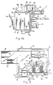
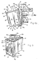
- the alignment of the nozzle plate and the loading of the interconnect strip 16 occurs when the user rotates the cartridge 14 in the direction of the arrow 82 (FIG. 6a), about the pivot point 56r. The user does this by squeezing the cartridge thumbhold 50a and the carriage finger hold 68 between the thumb and forefinger.
- the user Before the user can squeeze the cartridge 14 into its locked-in position, the user must be able to easily drop the cartridge into the carriage chute 20.
- the springs 58, 62 which align the cartridge 14 do not apply any force to the cartridge until the cartridge begins to rotate into the locked-in position (shown in FIG. 6b). This leaves an unobstructed path for the user to easily drop the cartridge 14 into the pre-rotation position, depicted in FIG. 6a.
- the side-kicker spring 58 applies light force when inserting the cartridge 14.
- the cartridge 14 rotates about the reference pads 56, specifically, point 56r. As the user rotates the cartridge 14, the alignment functions are performed before the electrical interconnect strip 16 is loaded. First, one side 36 of the cartridge 14 engages the molded-in carriage side spring 58. This spring 58 references the cartridge 14 in the X direction by pushing the cartridge sideways until the X reference pad 56x is touching the X reference pad 60x on the cartridge. The result is an accurate, no slop alignment of the nozzle plate in the X direction.
- the next action to occur is the alignment in the Z direction.
- the spring pushes the cartridge in the Z direction until the Z reference pads 56z are in contact with the Z reference pads 60z on the carriage 12.
- the result is an accurate, no slop registration of both the electrical interconnect 16 and the nozzle plate in the Z direction.
- the electrical interconnect concave contact pads 48 on the cartridge contact 46 get wiped slightly by the convex contact dimples 30 on the carriage interconnect strip 16. This offers improved reliability over the dimpled intercon nect on prior art printers, because the oxides and contamination are wiped off the contacts 30 and 48 before the interconnect 16 is loaded.
- the wiping action is followed by the alignment of the cartridge electrical contact pads 48 in the X direction. This occurs when the cartridge's outer rear heel lock tabs 84a,c engage the sides 86a,c of the heel lock slot 86 on the carriage 12.
- the interconnect strip 16 on the carriage 12 is referenced accurately to the heel lock slot 86 by pins 27, thereby providing the required alignment of the interconnect strip to the cartridge's electrical contact pads 48.
- the contact strip 46 is fastened, such as by glue or adhesive, to the cartridge 14 and is referenced by an assembly machine.
- the cartridge 14 is aligned accurately in the Y direction.
- the electrical interconnect's rubber spring pad 24 on the carriage 12 must be deflected the proper distance in the Y direction in order to maintain the required contact force.
- the rubber spring 24 pushes back against the electrical contacts 30 and 48 so that the Y reference pads 56y on the cartridge contact the Y reference pads 60y on the carriage. This maintains the necessary force on the contact pads 48 located on the contact strip 46, on the rear surface 42 of the cartridge 14.
- This also provides an accurate Y registration of the nozzle plate as well as controlling the rotational alignment of the nozzles.
- the required contact force in the Y and Z directions is maintained by the rear snap-spring 62.
- the rear lip 64 of the cartridge 14 deflects the rear spring-snap 62 and passes over an over-center point 62a (FIG. 6a) on the snap-spring.
- the snap-spring 62 is designed to apply about 70% of its force in the Y direction. This is the force required to maintain the electrical interconnect 16 in the rear 42 of the cartridge 14.
- the cartridge 14 passes the over-center point 62a on the rear snap-spring 62, the cartridge makes an audible "snap", signalling to the user that the cartridge is in the proper locked-in position.
- the force of the rubber interconnect spring pad 24 is adequate to hold the cartridge into its accurately aligned position under the large accelerations and shock loads the cartridge encounters in normal printing operations.
- the user To remove the cartridge 14 from the carriage 12, the user simply rotates the cartridge by squeezing the cartridge finger hold 50b and the carriage thumb hold 20b between the thumb and forefinger.
- the rear ledge 64 on the carriage 14 deflects the rear snap-spring 62 until the cartridge over-centers into the unlocked position. There is an audible “snap" which tells the user that the cartridge 14 can now be lifted out of the carriage 12 for disposal.
- the print cartridge/carriage assembly disclosed herein is suitably employed in ink-jet printers, particularly thermal ink-jet printers.
Landscapes
- Ink Jet (AREA)
- Common Mechanisms (AREA)
- Particle Formation And Scattering Control In Inkjet Printers (AREA)
Applications Claiming Priority (2)
| Application Number | Priority Date | Filing Date | Title |
|---|---|---|---|
| US11310187A | 1987-10-23 | 1987-10-23 | |
| US113101 | 1987-10-23 |
Publications (3)
| Publication Number | Publication Date |
|---|---|
| EP0313205A2 true EP0313205A2 (fr) | 1989-04-26 |
| EP0313205A3 EP0313205A3 (en) | 1990-02-28 |
| EP0313205B1 EP0313205B1 (fr) | 1994-11-17 |
Family
ID=22347586
Family Applications (1)
| Application Number | Title | Priority Date | Filing Date |
|---|---|---|---|
| EP88308397A Expired - Lifetime EP0313205B1 (fr) | 1987-10-23 | 1988-09-12 | Dispositif pour l'alignement de la tête d'impression et du chariot et mécanisme de verrouillage de l'interconnexion électronique |
Country Status (6)
| Country | Link |
|---|---|
| EP (1) | EP0313205B1 (fr) |
| JP (1) | JP3069105B2 (fr) |
| KR (1) | KR960012777B1 (fr) |
| CA (1) | CA1304983C (fr) |
| DE (1) | DE3852126T2 (fr) |
| SG (1) | SG2795G (fr) |
Cited By (40)
| Publication number | Priority date | Publication date | Assignee | Title |
|---|---|---|---|---|
| WO1991006432A1 (fr) * | 1989-10-30 | 1991-05-16 | Siemens Aktiengesellschaft | Imprimante a jet d'encre avec tetes d'impression interchangeables |
| EP0418821A3 (en) * | 1989-09-18 | 1991-12-27 | Canon Kabushiki Kaisha | Ink jet recording head carriage and an apparatus with same |
| EP0526062A1 (fr) * | 1991-07-31 | 1993-02-03 | Hewlett-Packard Company | Chariot pour dispositif d'écriture à jet d'encre |
| US5212502A (en) * | 1992-03-04 | 1993-05-18 | Eastman Kodak Company | Ink jet print head mounting mechanism |
| US5216448A (en) * | 1989-09-18 | 1993-06-01 | Canon Kabushiki Kaisha | Ink jet recording head carriage and an apparatus with same |
| EP0590669A1 (fr) * | 1992-09-30 | 1994-04-06 | Pitney Bowes, Inc. | Appareil pour fixer une cassette à jet d'encre sur son support |
| EP0581297A3 (en) * | 1992-07-30 | 1994-09-07 | Canon Kk | Recording head unit and recording apparatus using same |
| US5359357A (en) * | 1992-03-19 | 1994-10-25 | Fuji Xerox Co., Ltd. | Ink-jet recording apparatus |
| EP0622207A3 (fr) * | 1993-04-30 | 1995-04-19 | Hewlett Packard Co | Plate-forme commune pour cartouche à jet d'encre pour têtes d'impression différentes. |
| EP0622208A3 (fr) * | 1993-04-30 | 1995-04-19 | Hewlett Packard Co | Imprimante par jet d'encre avec chariot et cartouches d'encre. |
| EP0622206A3 (fr) * | 1993-04-30 | 1995-04-26 | Hewlett Packard Co | Ensemble de points de repère pour l'alignement d'éléments multi-buses dans une imprimante. |
| EP0622233A3 (fr) * | 1993-04-30 | 1995-06-07 | Hewlett Packard Co | Système d'interconnexion électrique pour une imprimante. |
| EP0622240A3 (fr) * | 1993-04-30 | 1996-04-03 | Hewlett Packard Co | Chariot modulaire pour imprimante par jet d'encre. |
| EP0622232A3 (fr) * | 1993-04-30 | 1996-05-01 | Hewlett Packard Co | Dispositif d'essuyage pour le nettoyage des contacts électriques dans une imprimante et cartouche d'encre. |
| EP0641666A3 (fr) * | 1993-09-03 | 1996-06-05 | Canon Kk | Appareil d'enregistrement avec mécanisme d'installation de la tête. |
| EP0738607A3 (fr) * | 1995-04-21 | 1997-12-10 | Canon Kabushiki Kaisha | Imprimante à tête d'impression amovible |
| US5751305A (en) * | 1995-09-29 | 1998-05-12 | Hewlett-Packard Company | Method and apparatus for dynamically aligning a printer printhead |
| US5847722A (en) * | 1995-11-21 | 1998-12-08 | Hewlett-Packard Company | Inkjet printhead alignment via measurement and entry |
| US5900898A (en) * | 1992-12-25 | 1999-05-04 | Canon Kabushiki Kaisha | Liquid jet head having a contoured and secured filter, liquid jet apparatus using same, and method of immovably securing a filter to a liquid receiving member of a liquid jet head |
| US6193350B1 (en) | 1995-09-29 | 2001-02-27 | Hewlett-Packard Company | Method and apparatus for dynamically aligning a printer printhead |
| WO2001049498A1 (fr) * | 2000-01-05 | 2001-07-12 | Hewlett-Packard Company | Cartouche d'impression a jet d'encre a profil reduit |
| US6260951B1 (en) | 1997-08-22 | 2001-07-17 | Xaar Technology Limited | Method of manufacturing of printing apparatus |
| EP1164019A3 (fr) * | 1994-05-31 | 2002-03-13 | Hewlett-Packard Company | Cassette de nettoyage pour mécanisme d'impression par jet d'encre |
| WO2007065189A1 (fr) * | 2005-12-05 | 2007-06-14 | Silverbrook Research Pty Ltd | Imprimante a jet d'encre comprenant un ensemble cartouche-tete d'impression et un support relies par un mecanisme a arc-boutement |
| US7357496B2 (en) | 2005-12-05 | 2008-04-15 | Silverbrook Research Pty Ltd | Inkjet printhead assembly with resilient ink connectors |
| US7431443B2 (en) | 2005-12-05 | 2008-10-07 | Silverbrook Research Pty Ltd | Ink reservoir with pressure regulating valve |
| US7431440B2 (en) | 2005-12-05 | 2008-10-07 | Silverbrook Research Pty Ltd | Ink reservoir with air bag |
| US7441882B2 (en) | 2005-12-05 | 2008-10-28 | Silverbrook Research Pty Ltd | Inkjet printer with printhead cartridge levered into operative position |
| US7465045B2 (en) | 2005-12-05 | 2008-12-16 | Silverbrook Research Pty Ltd | Printer with ink cartridge for engaging printhead cartridge and printer body |
| US7467863B2 (en) | 2005-12-05 | 2008-12-23 | Silverbrook Research Pty Ltd | Inkjet printer with disengageable maintenance station drive coupling |
| US7467852B2 (en) | 2005-12-05 | 2008-12-23 | Silverbrook Research Pty Ltd | Inkjet printer with printhead cartridge and ink cartridge |
| US7469990B2 (en) | 2005-12-05 | 2008-12-30 | Silverbrook Research Pty Ltd | Inkjet printer with printhead cartridge and cradle that interengage via an overcentre mechanism |
| US7513603B2 (en) | 2005-12-05 | 2009-04-07 | Silverbrook Research Pty Ltd | Printhead assembly with ink inlet valve |
| US7524023B2 (en) | 2005-12-05 | 2009-04-28 | Silverbrook Research Pty Ltd | Ink reservoir with constant hydrostatic pressure outlet |
| US7527353B2 (en) | 2005-12-05 | 2009-05-05 | Silverbrook Research Pty Ltd | Ink cartridge with sealed air inlet |
| US7556364B2 (en) | 2005-12-05 | 2009-07-07 | Silverbrook Research Pty Ltd | Ink cartridge with self sealing outlet valve |
| USRE41601E1 (en) | 1998-05-13 | 2010-08-31 | Seiko Epson Corporation | Ink cartridge for ink-jet printing apparatus |
| US8382266B2 (en) | 2004-01-21 | 2013-02-26 | Zamtec Ltd | Ink storage module with displaceable upper and lower plates and displaceable upper and lower collars |
| CN104723691A (zh) * | 2012-01-12 | 2015-06-24 | 精工爱普生株式会社 | 盒和印刷材料供应系统 |
| WO2023036891A1 (fr) * | 2021-09-09 | 2023-03-16 | Nsti Northern Scientific Tech & Integration Ug (Haftungsbeschränkt) | Module d'accueil pour système de tête d'impression, système de tête d'impression, système d'impression et procédé d'impression d'objets |
Families Citing this family (10)
| Publication number | Priority date | Publication date | Assignee | Title |
|---|---|---|---|---|
| JP2728912B2 (ja) * | 1988-12-29 | 1998-03-18 | キヤノン株式会社 | インクジェットカートリッジ及びインクジェット記録装置 |
| JP2763310B2 (ja) * | 1988-12-29 | 1998-06-11 | キヤノン株式会社 | インクジェットカートリッジ |
| JP2761065B2 (ja) * | 1989-12-25 | 1998-06-04 | キヤノン株式会社 | インクジェット記録装置 |
| JPH0433550U (fr) * | 1990-07-17 | 1992-03-18 | ||
| JP3352291B2 (ja) | 1994-08-04 | 2002-12-03 | キヤノン株式会社 | 情報処理装置 |
| JP3495926B2 (ja) | 1998-10-27 | 2004-02-09 | キヤノン株式会社 | 記録装置 |
| JP5190768B2 (ja) * | 2008-03-12 | 2013-04-24 | 富士ゼロックス株式会社 | 装着部材および電気機器 |
| CA2860539C (fr) * | 2012-01-12 | 2017-03-28 | Seiko Epson Corporation | Systeme d'alimentation pour cartouche et materiau d'impression |
| JP6221566B2 (ja) * | 2013-09-26 | 2017-11-01 | セイコーエプソン株式会社 | 液体収容容器の再生方法、および液体収容容器 |
| JP6930165B2 (ja) * | 2017-03-24 | 2021-09-01 | セイコーエプソン株式会社 | カートリッジおよび液体供給ユニット |
Family Cites Families (8)
| Publication number | Priority date | Publication date | Assignee | Title |
|---|---|---|---|---|
| DE3313205C1 (de) * | 1983-04-12 | 1984-10-04 | Siemens AG, 1000 Berlin und 8000 München | Vorrichtung zur Fuehrung einer Druckwerkes |
| JPS6020434A (ja) * | 1983-07-13 | 1985-02-01 | Hitachi Ltd | X線管用回転陽極複合タ−ゲツト |
| JPS60161160A (ja) * | 1984-01-31 | 1985-08-22 | Nec Home Electronics Ltd | ドツトラインプリンタ |
| JPH0712659B2 (ja) * | 1984-03-30 | 1995-02-15 | キヤノン株式会社 | インクジエツト記録装置 |
| JPS60204343A (ja) * | 1984-03-30 | 1985-10-15 | Canon Inc | インクジエツト記録装置 |
| JPS61125849A (ja) * | 1984-11-22 | 1986-06-13 | Canon Inc | 液体噴射記録装置 |
| US4570313A (en) * | 1984-12-31 | 1986-02-18 | G. A. Gray Division, The Warner & Swasey Company | Spindle lock-up device |
| DE3712891A1 (de) * | 1987-04-15 | 1988-11-03 | Siemens Ag | Planartintendruckkopf im dual-inline-gehaeuse |
-
1988
- 1988-09-08 CA CA000576767A patent/CA1304983C/fr not_active Expired - Lifetime
- 1988-09-12 EP EP88308397A patent/EP0313205B1/fr not_active Expired - Lifetime
- 1988-09-12 DE DE3852126T patent/DE3852126T2/de not_active Expired - Lifetime
- 1988-10-17 JP JP63261263A patent/JP3069105B2/ja not_active Expired - Lifetime
- 1988-10-22 KR KR1019880013841A patent/KR960012777B1/ko not_active Expired - Fee Related
-
1995
- 1995-01-10 SG SG2795A patent/SG2795G/en unknown
Cited By (63)
| Publication number | Priority date | Publication date | Assignee | Title |
|---|---|---|---|---|
| EP0418821A3 (en) * | 1989-09-18 | 1991-12-27 | Canon Kabushiki Kaisha | Ink jet recording head carriage and an apparatus with same |
| US5216448A (en) * | 1989-09-18 | 1993-06-01 | Canon Kabushiki Kaisha | Ink jet recording head carriage and an apparatus with same |
| WO1991006432A1 (fr) * | 1989-10-30 | 1991-05-16 | Siemens Aktiengesellschaft | Imprimante a jet d'encre avec tetes d'impression interchangeables |
| EP0526062A1 (fr) * | 1991-07-31 | 1993-02-03 | Hewlett-Packard Company | Chariot pour dispositif d'écriture à jet d'encre |
| US5212502A (en) * | 1992-03-04 | 1993-05-18 | Eastman Kodak Company | Ink jet print head mounting mechanism |
| US5359357A (en) * | 1992-03-19 | 1994-10-25 | Fuji Xerox Co., Ltd. | Ink-jet recording apparatus |
| EP0581297A3 (en) * | 1992-07-30 | 1994-09-07 | Canon Kk | Recording head unit and recording apparatus using same |
| US6151046A (en) * | 1992-07-30 | 2000-11-21 | Canon Kabushiki Kaisha | Recording head unit and recording apparatus using the same |
| US5561450A (en) * | 1992-09-30 | 1996-10-01 | Pitney Bowes Inc. | Apparatus for mounting an ink jet cartridge on a support therefor |
| EP0590669A1 (fr) * | 1992-09-30 | 1994-04-06 | Pitney Bowes, Inc. | Appareil pour fixer une cassette à jet d'encre sur son support |
| US5900898A (en) * | 1992-12-25 | 1999-05-04 | Canon Kabushiki Kaisha | Liquid jet head having a contoured and secured filter, liquid jet apparatus using same, and method of immovably securing a filter to a liquid receiving member of a liquid jet head |
| EP0622207A3 (fr) * | 1993-04-30 | 1995-04-19 | Hewlett Packard Co | Plate-forme commune pour cartouche à jet d'encre pour têtes d'impression différentes. |
| EP0622208A3 (fr) * | 1993-04-30 | 1995-04-19 | Hewlett Packard Co | Imprimante par jet d'encre avec chariot et cartouches d'encre. |
| EP0622232A3 (fr) * | 1993-04-30 | 1996-05-01 | Hewlett Packard Co | Dispositif d'essuyage pour le nettoyage des contacts électriques dans une imprimante et cartouche d'encre. |
| EP0622233A3 (fr) * | 1993-04-30 | 1995-06-07 | Hewlett Packard Co | Système d'interconnexion électrique pour une imprimante. |
| EP0622206A3 (fr) * | 1993-04-30 | 1995-04-26 | Hewlett Packard Co | Ensemble de points de repère pour l'alignement d'éléments multi-buses dans une imprimante. |
| US5598194A (en) * | 1993-04-30 | 1997-01-28 | Hewlett-Packard Company | Wiping structure for cleaning electrical contacts for a printer and ink cartridge |
| EP0622240A3 (fr) * | 1993-04-30 | 1996-04-03 | Hewlett Packard Co | Chariot modulaire pour imprimante par jet d'encre. |
| EP0807529A3 (fr) * | 1993-04-30 | 1998-02-11 | Hewlett-Packard Company | Assemblage à chariot pour retenir deux cartouches d'impression à jet d'encre |
| EP0641666A3 (fr) * | 1993-09-03 | 1996-06-05 | Canon Kk | Appareil d'enregistrement avec mécanisme d'installation de la tête. |
| US5923350A (en) * | 1993-09-03 | 1999-07-13 | Canon Kabushiki Kaisha | Recording apparatus with improved head installation mechanism |
| CN1060723C (zh) * | 1993-09-03 | 2001-01-17 | 佳能株式会社 | 记录装置和信息处理系统 |
| EP1164019A3 (fr) * | 1994-05-31 | 2002-03-13 | Hewlett-Packard Company | Cassette de nettoyage pour mécanisme d'impression par jet d'encre |
| EP0738607A3 (fr) * | 1995-04-21 | 1997-12-10 | Canon Kabushiki Kaisha | Imprimante à tête d'impression amovible |
| US6260950B1 (en) | 1995-04-21 | 2001-07-17 | Canon Kabushiki Kaisha | Ink jet printing system using printers with interchangeable printing units |
| US5751305A (en) * | 1995-09-29 | 1998-05-12 | Hewlett-Packard Company | Method and apparatus for dynamically aligning a printer printhead |
| US6193350B1 (en) | 1995-09-29 | 2001-02-27 | Hewlett-Packard Company | Method and apparatus for dynamically aligning a printer printhead |
| US5847722A (en) * | 1995-11-21 | 1998-12-08 | Hewlett-Packard Company | Inkjet printhead alignment via measurement and entry |
| US6260951B1 (en) | 1997-08-22 | 2001-07-17 | Xaar Technology Limited | Method of manufacturing of printing apparatus |
| USRE41601E1 (en) | 1998-05-13 | 2010-08-31 | Seiko Epson Corporation | Ink cartridge for ink-jet printing apparatus |
| AU766180B2 (en) * | 2000-01-05 | 2003-10-09 | Hewlett-Packard Development Company, L.P. | Ink-jet print cartridge having a low profile |
| WO2001049498A1 (fr) * | 2000-01-05 | 2001-07-12 | Hewlett-Packard Company | Cartouche d'impression a jet d'encre a profil reduit |
| US8382266B2 (en) | 2004-01-21 | 2013-02-26 | Zamtec Ltd | Ink storage module with displaceable upper and lower plates and displaceable upper and lower collars |
| US7845781B2 (en) | 2005-12-05 | 2010-12-07 | Silverbrook Research Pty Ltd | Printer with cartridge dock for rupturing seal on cartridge |
| US8075116B2 (en) | 2005-12-05 | 2011-12-13 | Silverbrook Research Pty Ltd | Ink cartridge with high flowrate, self sealing outlet |
| US7441882B2 (en) | 2005-12-05 | 2008-10-28 | Silverbrook Research Pty Ltd | Inkjet printer with printhead cartridge levered into operative position |
| US7465045B2 (en) | 2005-12-05 | 2008-12-16 | Silverbrook Research Pty Ltd | Printer with ink cartridge for engaging printhead cartridge and printer body |
| US7467863B2 (en) | 2005-12-05 | 2008-12-23 | Silverbrook Research Pty Ltd | Inkjet printer with disengageable maintenance station drive coupling |
| US7467852B2 (en) | 2005-12-05 | 2008-12-23 | Silverbrook Research Pty Ltd | Inkjet printer with printhead cartridge and ink cartridge |
| US7469990B2 (en) | 2005-12-05 | 2008-12-30 | Silverbrook Research Pty Ltd | Inkjet printer with printhead cartridge and cradle that interengage via an overcentre mechanism |
| US7513603B2 (en) | 2005-12-05 | 2009-04-07 | Silverbrook Research Pty Ltd | Printhead assembly with ink inlet valve |
| US7524023B2 (en) | 2005-12-05 | 2009-04-28 | Silverbrook Research Pty Ltd | Ink reservoir with constant hydrostatic pressure outlet |
| US7527353B2 (en) | 2005-12-05 | 2009-05-05 | Silverbrook Research Pty Ltd | Ink cartridge with sealed air inlet |
| US7556364B2 (en) | 2005-12-05 | 2009-07-07 | Silverbrook Research Pty Ltd | Ink cartridge with self sealing outlet valve |
| US7712880B2 (en) | 2005-12-05 | 2010-05-11 | Silverbrook Research Pty Ltd | Valve assembly with a pressure regulator for a printhead cartridge |
| US7771008B2 (en) | 2005-12-05 | 2010-08-10 | Silverbrook Research Pty Ltd | Printhead maintenance assembly for an inkjet printer |
| US7431443B2 (en) | 2005-12-05 | 2008-10-07 | Silverbrook Research Pty Ltd | Ink reservoir with pressure regulating valve |
| US7431440B2 (en) | 2005-12-05 | 2008-10-07 | Silverbrook Research Pty Ltd | Ink reservoir with air bag |
| WO2007065189A1 (fr) * | 2005-12-05 | 2007-06-14 | Silverbrook Research Pty Ltd | Imprimante a jet d'encre comprenant un ensemble cartouche-tete d'impression et un support relies par un mecanisme a arc-boutement |
| US8100518B2 (en) | 2005-12-05 | 2012-01-24 | Silverbrook Research Pty Ltd | Inkjet printer with resilient connection between printhead cartridge and ink cartridge |
| US8007092B2 (en) | 2005-12-05 | 2011-08-30 | Silverbrook Research Pty Ltd | Air tight ink cartridge with unobstructed ink outlet |
| US8011758B2 (en) | 2005-12-05 | 2011-09-06 | Silverbrook Research Pty Ltd | Printer with ink cartridge for sealed connection with inlet valve prior to valve actuation |
| US8011766B2 (en) | 2005-12-05 | 2011-09-06 | Silverbrook Research Pty Ltd | Printhead cartridge valve assembly with diaphragm pressure regulator |
| US7971965B2 (en) | 2005-12-05 | 2011-07-05 | Silverbrook Research Pty Ltd | Ink cartridge for constant ink pressure |
| US8087763B2 (en) | 2005-12-05 | 2012-01-03 | Silverbrook Research Pty Ltd | Inkjet printer with printhead cartridge and cradle that interengage via an overcentre mechanism |
| US8007089B2 (en) | 2005-12-05 | 2011-08-30 | Silverbrook Research Pty Ltd | Printer with printhead cartridge and printer body that simultaneously engage an ink cartridge |
| US8109621B2 (en) | 2005-12-05 | 2012-02-07 | Silverbrook Research Pty Ltd | Printer with mutually engaging ink cartridge, printhead cartridge and printer body |
| US8118416B2 (en) | 2005-12-05 | 2012-02-21 | Silverbrook Reasearch Pty Ltd | Valve assembly for a printer ink cartridge having a spring-biased pressure regulator |
| US8360548B2 (en) | 2005-12-05 | 2013-01-29 | Zamtec Ltd | Printhead maintenance assembly for inkjet printer |
| US8382268B2 (en) | 2005-12-05 | 2013-02-26 | Zamtec Ltd | Ink cartridge with high flow rate supply to printhead |
| US7357496B2 (en) | 2005-12-05 | 2008-04-15 | Silverbrook Research Pty Ltd | Inkjet printhead assembly with resilient ink connectors |
| CN104723691A (zh) * | 2012-01-12 | 2015-06-24 | 精工爱普生株式会社 | 盒和印刷材料供应系统 |
| WO2023036891A1 (fr) * | 2021-09-09 | 2023-03-16 | Nsti Northern Scientific Tech & Integration Ug (Haftungsbeschränkt) | Module d'accueil pour système de tête d'impression, système de tête d'impression, système d'impression et procédé d'impression d'objets |
Also Published As
| Publication number | Publication date |
|---|---|
| KR890006390A (ko) | 1989-06-13 |
| SG2795G (en) | 1995-06-16 |
| EP0313205B1 (fr) | 1994-11-17 |
| KR960012777B1 (ko) | 1996-09-24 |
| JP3069105B2 (ja) | 2000-07-24 |
| JPH01125238A (ja) | 1989-05-17 |
| EP0313205A3 (en) | 1990-02-28 |
| DE3852126D1 (de) | 1994-12-22 |
| CA1304983C (fr) | 1992-07-14 |
| DE3852126T2 (de) | 1995-03-23 |
Similar Documents
| Publication | Publication Date | Title |
|---|---|---|
| EP0313205A2 (fr) | Dispositif pour l'alignement de la tête d'impression et du chariot et mécanisme de verrouillage de l'interconnexion électronique | |
| US4907018A (en) | Printhead-carriage alignment and electrical interconnect lock-in mechanism | |
| US4872026A (en) | Ink-jet printer with printhead carriage alignment mechanism | |
| EP1000751B1 (fr) | Appareil d'enregistrement | |
| EP0379151B1 (fr) | Dispotif d'impression à jet d'encre et méthode d'installation d'une tete à jet d'encre sur un dispotif d'impression à jet d'encre | |
| US5208610A (en) | Pen carriage for an ink-jet printer | |
| EP0847866B1 (fr) | Réservoir d'alimentation en encre pour une unité d'enregistrement à jet d'encre | |
| US6209996B1 (en) | Method and apparatus for securing an ink container | |
| US6074042A (en) | Ink container having a guide feature for insuring reliable fluid, air and electrical connections to a printing system | |
| US5992975A (en) | Electrical interconnect for an ink container | |
| US4635080A (en) | Liquid injection recording apparatus | |
| EP0653306B1 (fr) | Poste de maintenance pour imprimante par jet d'encre | |
| GB2343658A (en) | Handheld inkjet printer with variable coefficient of friction between the printer and an image receiving medium | |
| USRE37671E1 (en) | Printhead-carriage alignment and electrical interconnect lock-in mechanism | |
| EP1078773B1 (fr) | Chariot avec membre protecteur des connections électriques et appareil d'enregistrement | |
| EP1234679B1 (fr) | Système de balayage pour deux dispositifs d'écriture | |
| EP3650235B1 (fr) | Imprimante portable | |
| EP0700784A1 (fr) | Appareil d'enregistrement par jet d'encre | |
| JP2002337358A (ja) | インクカートリッジ | |
| JPS60192676A (ja) | インクジエツト記録装置 | |
| JPH02235777A (ja) | インクジェット・プリンタ | |
| JPH0986012A (ja) | インクジェット記録装置 | |
| JPH08507981A (ja) | 電子プリンタ用のインキリボンガイド部 | |
| HK1012499B (en) | Ink supply tank for an ink jet type recording unit | |
| HK1011657B (en) | Ink jet type recording unit, and printer with it |
Legal Events
| Date | Code | Title | Description |
|---|---|---|---|
| PUAI | Public reference made under article 153(3) epc to a published international application that has entered the european phase |
Free format text: ORIGINAL CODE: 0009012 |
|
| AK | Designated contracting states |
Kind code of ref document: A2 Designated state(s): DE FR GB IT |
|
| PUAL | Search report despatched |
Free format text: ORIGINAL CODE: 0009013 |
|
| AK | Designated contracting states |
Kind code of ref document: A3 Designated state(s): DE FR GB IT |
|
| 17P | Request for examination filed |
Effective date: 19900802 |
|
| 17Q | First examination report despatched |
Effective date: 19921111 |
|
| GRAA | (expected) grant |
Free format text: ORIGINAL CODE: 0009210 |
|
| AK | Designated contracting states |
Kind code of ref document: B1 Designated state(s): DE FR GB IT |
|
| REF | Corresponds to: |
Ref document number: 3852126 Country of ref document: DE Date of ref document: 19941222 |
|
| ET | Fr: translation filed | ||
| ITF | It: translation for a ep patent filed | ||
| PLBE | No opposition filed within time limit |
Free format text: ORIGINAL CODE: 0009261 |
|
| STAA | Information on the status of an ep patent application or granted ep patent |
Free format text: STATUS: NO OPPOSITION FILED WITHIN TIME LIMIT |
|
| 26N | No opposition filed | ||
| REG | Reference to a national code |
Ref country code: GB Ref legal event code: 732E |
|
| REG | Reference to a national code |
Ref country code: FR Ref legal event code: TP |
|
| REG | Reference to a national code |
Ref country code: GB Ref legal event code: IF02 |
|
| PGFP | Annual fee paid to national office [announced via postgrant information from national office to epo] |
Ref country code: GB Payment date: 20070926 Year of fee payment: 20 |
|
| PGFP | Annual fee paid to national office [announced via postgrant information from national office to epo] |
Ref country code: IT Payment date: 20070927 Year of fee payment: 20 Ref country code: DE Payment date: 20071031 Year of fee payment: 20 |
|
| PGFP | Annual fee paid to national office [announced via postgrant information from national office to epo] |
Ref country code: FR Payment date: 20070917 Year of fee payment: 20 |
|
| REG | Reference to a national code |
Ref country code: GB Ref legal event code: PE20 Expiry date: 20080911 |
|
| PG25 | Lapsed in a contracting state [announced via postgrant information from national office to epo] |
Ref country code: GB Free format text: LAPSE BECAUSE OF EXPIRATION OF PROTECTION Effective date: 20080911 |