EP0700784A1 - Appareil d'enregistrement par jet d'encre - Google Patents
Appareil d'enregistrement par jet d'encre Download PDFInfo
- Publication number
- EP0700784A1 EP0700784A1 EP95112689A EP95112689A EP0700784A1 EP 0700784 A1 EP0700784 A1 EP 0700784A1 EP 95112689 A EP95112689 A EP 95112689A EP 95112689 A EP95112689 A EP 95112689A EP 0700784 A1 EP0700784 A1 EP 0700784A1
- Authority
- EP
- European Patent Office
- Prior art keywords
- carriage
- ink
- jet recording
- wiping
- printing area
- Prior art date
- Legal status (The legal status is an assumption and is not a legal conclusion. Google has not performed a legal analysis and makes no representation as to the accuracy of the status listed.)
- Granted
Links
Images


Classifications
-
- B—PERFORMING OPERATIONS; TRANSPORTING
- B41—PRINTING; LINING MACHINES; TYPEWRITERS; STAMPS
- B41J—TYPEWRITERS; SELECTIVE PRINTING MECHANISMS, i.e. MECHANISMS PRINTING OTHERWISE THAN FROM A FORME; CORRECTION OF TYPOGRAPHICAL ERRORS
- B41J2/00—Typewriters or selective printing mechanisms characterised by the printing or marking process for which they are designed
- B41J2/005—Typewriters or selective printing mechanisms characterised by the printing or marking process for which they are designed characterised by bringing liquid or particles selectively into contact with a printing material
- B41J2/01—Ink jet
- B41J2/135—Nozzles
- B41J2/165—Prevention or detection of nozzle clogging, e.g. cleaning, capping or moistening for nozzles
- B41J2/16517—Cleaning of print head nozzles
- B41J2/16535—Cleaning of print head nozzles using wiping constructions
- B41J2/16544—Constructions for the positioning of wipers
-
- B—PERFORMING OPERATIONS; TRANSPORTING
- B41—PRINTING; LINING MACHINES; TYPEWRITERS; STAMPS
- B41J—TYPEWRITERS; SELECTIVE PRINTING MECHANISMS, i.e. MECHANISMS PRINTING OTHERWISE THAN FROM A FORME; CORRECTION OF TYPOGRAPHICAL ERRORS
- B41J2/00—Typewriters or selective printing mechanisms characterised by the printing or marking process for which they are designed
- B41J2/005—Typewriters or selective printing mechanisms characterised by the printing or marking process for which they are designed characterised by bringing liquid or particles selectively into contact with a printing material
- B41J2/01—Ink jet
- B41J2/135—Nozzles
- B41J2/165—Prevention or detection of nozzle clogging, e.g. cleaning, capping or moistening for nozzles
- B41J2/16517—Cleaning of print head nozzles
- B41J2002/16576—Cleaning means pushed or actuated by print head movement
Definitions
- the present invention relates to an ink-jet recording apparatus.
- Ink-jet recording apparatus are designed so that drops of ink pressurized by piezoelectric transducers or heat generating elements in pressure generating chambers are sent out of nozzle holes. Consequently, there arise cases where dust and paper powder stick to the nozzle holes, where ink coagulates and where the nozzle holes are clogged when the holes become dried. Therefore, consequences resultant from variations in the ink-drop discharge characteristic badly affect recording heads for use in writing recording data.
- such an ink-jet recording apparatus has been equipped with a cap member for sealing up each nozzle hole during the non-printing operation, and a cleaning unit having an elastic plate for rubbing the opening of the nozzle hole to remove dust and ink dregs during the printing operation.
- the cap member and the cleaning unit have been small-sized because a casing affords an extremely small space. It has also been arranged that the recording head is interlocked with the movement of a carriage so as to make a special driving source unnecessary for moving the recording head back and forth.
- a recording apparatus that has been given in Japanese Unexamined Patent Publication No. 42675/1993, for example, is equipped with a cap member and a cleaning unit.
- a slider kept urged by a spring toward a printing area is made to follow the movement of a carriage and when the carriage is positioned in a non-printing area, a capping member is caused to abut against a recording head and when the recording head is moved to the printing area from the capping state, a wiping member is projected toward the recording head to perform the wiping operation.
- the wiping means is moved back to the original position.
- the aforesaid ink-jet recording apparatus is capable of not only having the capping operation performed by moving the carriage but also automatically moving the wiping means back and forth without necessitating a special driving means, whereby the ink-jet recording apparatus is made compact.
- the force of the spring for urging the slider toward the printing area needs to be strong enough to keep the wiping means at the original position.
- the problem is that in a case where a small motor is used to drive the carriage in a small printer, the motor will become heavily loaded, thus accelerating the battery power consumption.
- a wiper blade may be left in such a state that it has been kept forward because of trouble resulting from the suspension of the operation of the system during the wrong operation performed by the user, during carrying the recording apparatus in the wrong direction or during retracting the wiper blade to the non-wiping position. If, moreover, the recording head moved back to the non-printing area makes contact with the wiper blade thus projected, it will receive excessive wiping energy, thus causing a nozzle plate to wear away or causing the blade to become deformed.
- the present invention intends to overcome these problems.
- the object is solved by the ink-jet recording apparatus according to independent claims 1, 3, 9.
- the present invention relates to an ink-jet recording apparatus for recording data by sending a stream of drops of ink from nozzle holes in conformity with printing data, and more particularly to a mechanism of maintaining the nozzle holes.
- an aspect of the present invention is to provide an ink-jet recording apparatus capable of retracting its slider whose movement is interlocked with that of the carriage without applying useless energizing force to the slider and without wiping the recording head when the recording head is moved from a printing area to the non-printing area even though the wiping blade is kept in such a state that it becomes protruded at the wiping position for some reason.
- an ink-jet recording apparatus including: an ink-jet recording head; a carriage on which the ink-jet recording head is mounted, the carriage being capable of traveling, between a printing and a non-printing area, the carriage having an operating lever on non-printing area thereof; and a wiper for wiping the ink-jet recording head in the non-printing area, the wiper having a projected piece including two tilted sides, the tilted sides being projecting toward the passage in which the carriage moves when the wiper is set in position where the wiper is capable of wiping, wherein, while the carriage is moved in the directions of printing and non-printing area of the carriage, the operating lever comes in contact with the projected piece of the wiping lever so as to move the wiping means out of the traveling passage of the carriage.
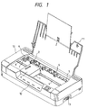
- An ink-jet recording apparatus as shown in Fig. 1 with an open outer cover 11 of a casing 10 taking away a middle cover simultaneously for use as a paper guide, is provided with a carriage 1 for carrying an ink cartridge 3 incorporating an ink-jet recording head 2, and a guide member 4 for guiding the carriage 1, the carriage 1 being reciprocated by a drive mechanism (not shown) between a printing and a non-printing area.
- a paper feed roller 5 and a paper holding-down roller 6 are installed in parallel to the guide member 4, whereas a head regenerating unit 9 having a cleaning member 7 and a cap member 8 is installed in the non-printing area.
- reference numeral 12 in Fig. 1 denotes an operating panel; and 13, a connector connected to a host.
- Fig. 2 is a view of an embodiment of the head regenerating unit of the aforesaid apparatus of the invention.
- the head regenerating unit 9 comprises a slider 20 serving as a moving member which abuts against part of the carriage 1 and follows in the direction in which the carriage 1 moves; a wiper lever 22 serving as a wiping means which is pivotally supported by part of the slider 20 and urged by a two-way stabilizing spring 21 so as to be pivotally displaced between the wiping and non-wiping positions; and a cap lever 23 which is made to engage with part of the slider 20 and pivotally moved between the capping and non-capping positions.
- the slider 20 is installed in such a way that it is urged by a cap lever spring 24 via the cap lever 23 to stay ordinarily at the stand-by position closer to the printing area, and guided by a guide rail 26 on a unit body 25 so as to follows the movement of the carriage 1.
- the mating portion 28 of the cap lever 23 is slidably arranged between two elevated parts 27, 27 provided in a direction perpendicular to the direction in which the slider 20 travels. Further, a cap 30 is displaced between the capping and non-capping positions by rocking the cap lever 23 pivotally supported on the shaft 29 of the unit body 25 interlockingly with the movement of the slider 20.
- the wiper lever 22 is provided with a slit 22a into which a wiper 31 in the form of a rubber or felt plate is fitted. Further, the wiper lever 22 also has a pivotal portion 33 of a fork 33a, 33a whose non-printing area side (the left-hand side of Fig. 3) is expensively opened at one-side lower end, the fork 33a, 33a being horizontally extending.
- the wiper lever 22 is pivotally supported by the slider 20 so that the former is capable of rocking.
- the pivotal portion 33 of the wiper lever 22 is mated with a support shaft 34 uprightly fitted to the slider 20 and the rear end (the upper end of Fig. 3) of the wiper lever 22 is kept in resilient contact with a flat spring 32 having a planar portion 32a with one end fixed to the unit body 25, and tilted sides 32b and 32c.
- the wiper lever 22 functions as what relates the positioning of the wiper 31 to the movement of the recording head 2 and moves the wiper 31 back to the non-wiping position.
- the wiper lever 22 is urged by the two-way stabilizing spring 21 stretched between a pin 35 provided on the slider 20 opposite to the support shaft 34 and a fulcrum pin 36 projected at the lower end of the leading end portion of the wiper lever 22.
- the two-way stabilizing spring 21 is urged toward one side with the support shaft 34 as the boundary; in other words, when the spring 21 is located above or under the support shaft 34, the wiper 31 is turned to the wiping or non-wiping position, so that the position of the wiper 31 may be stabilized.
- the wiper lever 22 has a chevron projection 41 such that the projection 41 projects within the passage of an operating lever 40 provided at the end of the carriage when the wiper lever 22 is displaced toward the wiping position.
- the apex of a chevron projection 40 is formed as a positioning plane 45 abutting against a reference plane 2b one-step lower than the nozzle plane 2a of the recording head 2 and when the wiper lever 22 is urged by the two-way stabilizing Spring 21 to rotate clockwise as shown in Figs. 4(a) and 4(b), the positioning plane 45 is caused to abut against the reference plane 2b so as to keep constant the interference quantity ⁇ between the leading end of the wiper 22 and the nozzle plane 2a, irrespective of the presence or absence of an error in view of assemblage, so that optimum wiping can be carried out.
- Reference numeral 50 in Figs. 4(a) and 4(b) denotes a tube pump fitted to the unit body 25; and 51, a tube with one end coupled to the cap 30, the other communicating with a waste ink tank (not shown).
- the slider 20 stays in the stand-by condition with its sealing side caused to face the printing area (on the right-hand side of Fig. 2) because of the cap lever spring 24 via the cap lever 23 as shown in Fig. 2.
- the wiper lever 22 rotates counterclockwise around the support shaft 34 on the slider 20 and because of the tensile strength of the two-way stabilizing spring 21 biased to the left-hand side of the support shaft 34, remains stationary after causing the chevron projection 41 to take shelter in the position indicated by an actual line of Fig. 2, that is, from the moving area of the operating lever 40.
- the recording head 2 on the carriage 1 presses a projection 37 with its side 2c as shown in Fig. 4(a) and 4(b) to make the slider 20 move to the end of the non-printing area, that is, to the end on the left-hand side of Fig. 4(a) against the force of the cap lever spring 24.
- the cap lever 23 with one end pivotally supported by the shaft 29 of the unit body 25 rotates clockwise around the shaft 29 as shown in Fig. 4(a) and 4(b) and sticks the cap 30 onto the nozzle plane of the recording head 2.
- the wiper lever 22 together with the slider 20 is simultaneously moved via the support shaft 34 to the non-printing area side and its upper end is separated from the flat spring 32, so chat the tilted aide 38 of the unit body 25 causes a fulcrum pin 36 to rotate clockwise. Consequently, the two-way stabilizing spring 21 is rotated clockwise in excess of the two-way stabilizing neutral point, and the edge face 44 of the chevron projection 41 is caused to abut against the side of the elevated part on the slider 20, whereby the wiper 22 is turned to be displaced slightly clockwise, that is, slightly away from the vertical line with respect to head 2 before being set stationary at a predetermined position (Figs. 4(a) and 4(b)).
- a tube pump 50 is operated in this condition to supply negative pressure to the recording head 2 so as to force ink to be discharged for regenerating purposes.
- the wiper lever 22 When the slider 20 is moved, the wiper lever 22 is displaced slightly clockwise, that is, slightly away from the vertical line and held in this direction before being moved to the printing area side because of the resilient force of the two-way stabilizing spring 21 in addition to the side 44 of the chevron projection 41 in abutment with the elevated part 27 of the slider 20.
- the positioning plane 45 at the tip of the chevron projection 41 abuts against the reference plane of the recording head 2 and keeps the predetermined interference quantity ⁇ between the wiper 31 and the nozzle plane 2a of the recording head 2.
- the wiper lever 22 When the slider 20 is moved to the right-hand end of the non-printing area in this condition, the wiper lever 22 allows its upper end to slide on the tilted side 32b of the flat spring 32 and slides into the planar portion 32a. With its resilient force, the wiper lever 22 is resiliently pressed against the recording head 2, and a blade of the wiper 31 is set perpendicular to the direction in which the carriage 1 moves.
- the recording head 2 makes the wiper 31 in abutment with the nozzle plane 2a become arched and subjected to wiping action. While maintaining the posture, the recording head 2 together with the slider 20 is further moved to the printing area side (on the right-hand side of Fig. 5(a)) and separated from the wiper 31.
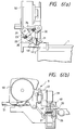
- the operating lever 40 comes into contact with the tilted side 43 of the chevron projection 41 as shown in Figs. 6(a) and 6(b) and rotates the projection 41 counterclockwise.
- the wiper lever 22 is caused to rotate counterclockwise against the resilient force of the flat spring 32 and while its upper end is supported by the tilted side 32b of the flat spring 32, the wiper lever 22 is held in the original non-wiping position, that is, in the wiper reset position shown in Fig. 2.
- the upper end of the wiper lever 22 is separated from the flat spring 32 as noted previously. Accordingly, the fulcrum pin 36 is caused to rotate clockwise because of the tilted side 38 of the unit body 25 as well as the energizing force of the two-way stabilizing spring 21, and become perpendicular to the direction in which the carriage 1 moves.
- the upper end of the wiper lever 22 is held on the planar portion 32a of the flat spring 32 while the slider is made to return to the original position by the energizing force of the spring 24 and set to the wiping position erroneously.
- the operating lever 40 When the carriage 1 is moved to the non-printing area in that condition, the operating lever 40 first comes into contact with the tilted side 42 of the printing area of the chevron projection 41 and raises the leading end 42a, thus forcing the wiper lever 22 to rotate counterclockwise as shown by a two-dot chain line of Fig. 2.
- the wiper lever 22 When the carriage 1 is moved to the non-printing area, further, the wiper lever 22 is uprighted with respect to the movement of the carriage 1 as shown in Fig. 2, and the cap 30 is made to hermetically adhere to the nozzle plane of the recording head 2.
- the projected piece having two tilted sides projecting in the passage in which the carriage moves when the wiping means is set in the position where the wiping operation can be performed.
- the carriage is equipped with the operating lever on the non-printing area side. The operating lever abuts against the projected piece when the carriage moves to the printing area and the non-printing area to make the wiping means take shelter from the travel passage.
- the recording head can be moved to the capping position after the wiping means is automatically reset to the normal position at the time the carriage is reset to the non-printing area of the carriage without providing for the slider the energizing force surely strong enough to move back the wiping means. It is thus possible to prevent useless wiping from be applied to the recording head.
Landscapes
- Ink Jet (AREA)
Applications Claiming Priority (6)
| Application Number | Priority Date | Filing Date | Title |
|---|---|---|---|
| JP18965494 | 1994-08-11 | ||
| JP18965494 | 1994-08-11 | ||
| JP189654/94 | 1994-08-11 | ||
| JP21984395 | 1995-08-04 | ||
| JP21984395A JP3322291B2 (ja) | 1994-08-11 | 1995-08-04 | インクジェット記録装置 |
| JP219843/95 | 1995-08-04 |
Publications (2)
| Publication Number | Publication Date |
|---|---|
| EP0700784A1 true EP0700784A1 (fr) | 1996-03-13 |
| EP0700784B1 EP0700784B1 (fr) | 2001-06-27 |
Family
ID=26505591
Family Applications (1)
| Application Number | Title | Priority Date | Filing Date |
|---|---|---|---|
| EP95112689A Expired - Lifetime EP0700784B1 (fr) | 1994-08-11 | 1995-08-11 | Appareil d'enregistrement par jet d'encre |
Country Status (4)
| Country | Link |
|---|---|
| US (1) | US5793391A (fr) |
| EP (1) | EP0700784B1 (fr) |
| JP (1) | JP3322291B2 (fr) |
| DE (1) | DE69521463T2 (fr) |
Families Citing this family (8)
| Publication number | Priority date | Publication date | Assignee | Title |
|---|---|---|---|---|
| DE19726643C1 (de) * | 1997-06-18 | 1998-07-23 | Francotyp Postalia Gmbh | Vorrichtung zur Reinigung eines Tintendruckkopfes |
| JP2972667B2 (ja) * | 1997-08-11 | 1999-11-08 | 新潟日本電気株式会社 | インクジェット記録装置 |
| US6371595B1 (en) * | 1998-09-19 | 2002-04-16 | Brother Kogyo Kabushiki Kaisha | Ink jet printer |
| US6464326B1 (en) | 1999-12-03 | 2002-10-15 | Hewlett-Packard Company | Wiping apparatus for an ink cartridge |
| US6350008B1 (en) * | 2000-09-28 | 2002-02-26 | Acer Communications And Multimedia Inc. | Ink jet station assembly |
| JP4288595B2 (ja) * | 2004-03-08 | 2009-07-01 | ブラザー工業株式会社 | インクジェットプリンタ |
| US7705181B2 (en) * | 2005-03-01 | 2010-04-27 | Basf Akiengesellschaft | Process for removing methacrylic acid from liquid phase comprising acrylic acid as a main constituent and target product, and methacrylic acid as a secondary component |
| WO2019212464A1 (fr) * | 2018-04-30 | 2019-11-07 | Hewlett-Packard Development Company, L.P. | Entretien de têtes d'impression |
Citations (6)
| Publication number | Priority date | Publication date | Assignee | Title |
|---|---|---|---|---|
| EP0094220A1 (fr) * | 1982-05-06 | 1983-11-16 | Sharp Kabushiki Kaisha | Mécanisme de recouvrement pour empêcher un colmatage de buse dans une imprimante à jets d'encre |
| JPS59162056A (ja) * | 1983-03-04 | 1984-09-12 | Canon Inc | インクジエツト記録装置 |
| EP0494674A1 (fr) * | 1991-01-09 | 1992-07-15 | Seiko Epson Corporation | Dispositif de recourrement pour imprimante à jet d'encre |
| JPH0542675A (ja) | 1991-08-09 | 1993-02-23 | Canon Inc | インクジエツト記録装置 |
| EP0589582A2 (fr) * | 1992-09-21 | 1994-03-30 | Hewlett-Packard Company | Méthode et appareil pour le recouvrement et le nettoyage d'une tête d'impression par jet d'encre |
| EP0604068A2 (fr) * | 1992-12-21 | 1994-06-29 | Hewlett-Packard Company | Dispositif de maintenance pour tête d'impression |
Family Cites Families (12)
| Publication number | Priority date | Publication date | Assignee | Title |
|---|---|---|---|---|
| JP2528635B2 (ja) * | 1986-04-09 | 1996-08-28 | キヤノン株式会社 | インクジェット装置 |
| JP2527774B2 (ja) * | 1987-12-29 | 1996-08-28 | キヤノン株式会社 | インクジェット記録装置 |
| EP0435695B1 (fr) * | 1989-12-29 | 1996-05-29 | Canon Kabushiki Kaisha | Appareil d'enregistrement à jet d'encre |
| JP2872431B2 (ja) * | 1991-04-22 | 1999-03-17 | キヤノン株式会社 | インクジェット記録装置 |
| JP2955384B2 (ja) * | 1991-04-26 | 1999-10-04 | キヤノン株式会社 | 画像記録装置 |
| JP2942031B2 (ja) * | 1991-09-30 | 1999-08-30 | キヤノン株式会社 | インクジェット記録装置 |
| JP3180401B2 (ja) * | 1991-12-24 | 2001-06-25 | セイコーエプソン株式会社 | インクジェットプリンタにおけるインク吐出回復装置 |
| US5608432A (en) * | 1993-06-22 | 1997-03-04 | Canon Kabushiki Kaisha | Ink jet apparatus and recovery mechanism therefor |
| US5559539A (en) * | 1993-10-12 | 1996-09-24 | Dataproducts Corporation | Ink jet recording apparatus having self aligning print head cleaning system and method of operating the print head cleaning system |
| JPH07137270A (ja) * | 1993-11-16 | 1995-05-30 | Canon Inc | インクジェット記録装置 |
| JP3317020B2 (ja) * | 1994-05-24 | 2002-08-19 | 富士ゼロックス株式会社 | インクジェット記録装置 |
| US5627574A (en) * | 1995-01-04 | 1997-05-06 | Brother International Corporation | Maintenance device in an ink jet printing apparatus |
-
1995
- 1995-08-04 JP JP21984395A patent/JP3322291B2/ja not_active Expired - Fee Related
- 1995-08-11 US US08/514,141 patent/US5793391A/en not_active Expired - Fee Related
- 1995-08-11 DE DE69521463T patent/DE69521463T2/de not_active Expired - Lifetime
- 1995-08-11 EP EP95112689A patent/EP0700784B1/fr not_active Expired - Lifetime
Patent Citations (6)
| Publication number | Priority date | Publication date | Assignee | Title |
|---|---|---|---|---|
| EP0094220A1 (fr) * | 1982-05-06 | 1983-11-16 | Sharp Kabushiki Kaisha | Mécanisme de recouvrement pour empêcher un colmatage de buse dans une imprimante à jets d'encre |
| JPS59162056A (ja) * | 1983-03-04 | 1984-09-12 | Canon Inc | インクジエツト記録装置 |
| EP0494674A1 (fr) * | 1991-01-09 | 1992-07-15 | Seiko Epson Corporation | Dispositif de recourrement pour imprimante à jet d'encre |
| JPH0542675A (ja) | 1991-08-09 | 1993-02-23 | Canon Inc | インクジエツト記録装置 |
| EP0589582A2 (fr) * | 1992-09-21 | 1994-03-30 | Hewlett-Packard Company | Méthode et appareil pour le recouvrement et le nettoyage d'une tête d'impression par jet d'encre |
| EP0604068A2 (fr) * | 1992-12-21 | 1994-06-29 | Hewlett-Packard Company | Dispositif de maintenance pour tête d'impression |
Non-Patent Citations (1)
| Title |
|---|
| PATENT ABSTRACTS OF JAPAN vol. 9, no. 14 (M - 352)<1737> 22 January 1985 (1985-01-22) * |
Also Published As
| Publication number | Publication date |
|---|---|
| US5793391A (en) | 1998-08-11 |
| DE69521463T2 (de) | 2002-05-29 |
| JP3322291B2 (ja) | 2002-09-09 |
| JPH08104010A (ja) | 1996-04-23 |
| DE69521463D1 (de) | 2001-08-02 |
| EP0700784B1 (fr) | 2001-06-27 |
Similar Documents
| Publication | Publication Date | Title |
|---|---|---|
| JP3495926B2 (ja) | 記録装置 | |
| JP3217610B2 (ja) | インクジェット記録装置および情報処理システム | |
| JPH068460A (ja) | インクジェット記録装置 | |
| US5793391A (en) | Ink-jet recording apparatus | |
| EP1375155A1 (fr) | Cartouche d'encre | |
| EP0435666B1 (fr) | Dispositif de récupération par aspiration et appareil d'enregistrement à jet d'encre comportant le dispositif | |
| US20040021727A1 (en) | Ink jet recording apparatus and recovery mechanism portion of ink jet recording apparatus | |
| US6241336B1 (en) | Ink-jet printer with printing head cap | |
| US6123407A (en) | Ink jet recording apparatus | |
| JP2698638B2 (ja) | インクタンク一体型記録ヘッドカートリッジ、該カートリッジを搭載するキャリッジおよびこれらを用いるインクジェット記録装置 | |
| JPH11277731A5 (fr) | ||
| JPH10296987A (ja) | インクジェット記録装置のキャッピング装置 | |
| JP3332590B2 (ja) | 記録装置 | |
| US8960859B2 (en) | Ink jet printing apparatus | |
| JP2746632B2 (ja) | 液体噴射記録装置 | |
| US6095634A (en) | Manual printing device | |
| JP4125297B2 (ja) | 液体吐出装置 | |
| JP3111781B2 (ja) | インクジェットヘッドのキャッピング装置 | |
| US20160052284A1 (en) | Recording apparatus with mounting-removing mechanism for ink cartridge | |
| JP2000218822A (ja) | インクジェット記録装置 | |
| JP3342301B2 (ja) | インクジェットヘッドの回復装置 | |
| JP3712221B2 (ja) | インクジェット式記録装置 | |
| US6854838B2 (en) | Ink jet printer | |
| JP3253763B2 (ja) | インクジェット記録装置 | |
| JP2799720B2 (ja) | インクジェット記録装置 |
Legal Events
| Date | Code | Title | Description |
|---|---|---|---|
| PUAI | Public reference made under article 153(3) epc to a published international application that has entered the european phase |
Free format text: ORIGINAL CODE: 0009012 |
|
| AK | Designated contracting states |
Kind code of ref document: A1 Designated state(s): DE FR GB IT |
|
| 17P | Request for examination filed |
Effective date: 19960515 |
|
| 17Q | First examination report despatched |
Effective date: 19970320 |
|
| GRAG | Despatch of communication of intention to grant |
Free format text: ORIGINAL CODE: EPIDOS AGRA |
|
| GRAG | Despatch of communication of intention to grant |
Free format text: ORIGINAL CODE: EPIDOS AGRA |
|
| GRAH | Despatch of communication of intention to grant a patent |
Free format text: ORIGINAL CODE: EPIDOS IGRA |
|
| GRAH | Despatch of communication of intention to grant a patent |
Free format text: ORIGINAL CODE: EPIDOS IGRA |
|
| GRAA | (expected) grant |
Free format text: ORIGINAL CODE: 0009210 |
|
| AK | Designated contracting states |
Kind code of ref document: B1 Designated state(s): DE FR GB IT |
|
| ITF | It: translation for a ep patent filed | ||
| REF | Corresponds to: |
Ref document number: 69521463 Country of ref document: DE Date of ref document: 20010802 |
|
| ET | Fr: translation filed | ||
| REG | Reference to a national code |
Ref country code: GB Ref legal event code: IF02 |
|
| PLBE | No opposition filed within time limit |
Free format text: ORIGINAL CODE: 0009261 |
|
| STAA | Information on the status of an ep patent application or granted ep patent |
Free format text: STATUS: NO OPPOSITION FILED WITHIN TIME LIMIT |
|
| 26N | No opposition filed | ||
| PGFP | Annual fee paid to national office [announced via postgrant information from national office to epo] |
Ref country code: GB Payment date: 20120808 Year of fee payment: 18 |
|
| PGFP | Annual fee paid to national office [announced via postgrant information from national office to epo] |
Ref country code: FR Payment date: 20120823 Year of fee payment: 18 Ref country code: DE Payment date: 20120808 Year of fee payment: 18 Ref country code: IT Payment date: 20120809 Year of fee payment: 18 |
|
| GBPC | Gb: european patent ceased through non-payment of renewal fee |
Effective date: 20130811 |
|
| PG25 | Lapsed in a contracting state [announced via postgrant information from national office to epo] |
Ref country code: DE Free format text: LAPSE BECAUSE OF NON-PAYMENT OF DUE FEES Effective date: 20140301 |
|
| REG | Reference to a national code |
Ref country code: DE Ref legal event code: R119 Ref document number: 69521463 Country of ref document: DE Effective date: 20140301 |
|
| REG | Reference to a national code |
Ref country code: FR Ref legal event code: ST Effective date: 20140430 |
|
| PG25 | Lapsed in a contracting state [announced via postgrant information from national office to epo] |
Ref country code: IT Free format text: LAPSE BECAUSE OF NON-PAYMENT OF DUE FEES Effective date: 20130811 |
|
| PG25 | Lapsed in a contracting state [announced via postgrant information from national office to epo] |
Ref country code: GB Free format text: LAPSE BECAUSE OF NON-PAYMENT OF DUE FEES Effective date: 20130811 |
|
| PG25 | Lapsed in a contracting state [announced via postgrant information from national office to epo] |
Ref country code: FR Free format text: LAPSE BECAUSE OF NON-PAYMENT OF DUE FEES Effective date: 20130902 |