EP0313237A1 - Hohlbohrer - Google Patents
Hohlbohrer Download PDFInfo
- Publication number
- EP0313237A1 EP0313237A1 EP88309365A EP88309365A EP0313237A1 EP 0313237 A1 EP0313237 A1 EP 0313237A1 EP 88309365 A EP88309365 A EP 88309365A EP 88309365 A EP88309365 A EP 88309365A EP 0313237 A1 EP0313237 A1 EP 0313237A1
- Authority
- EP
- European Patent Office
- Prior art keywords
- cutting edges
- teeth
- cutter
- crest
- axially
- Prior art date
- Legal status (The legal status is an assumption and is not a legal conclusion. Google has not performed a legal analysis and makes no representation as to the accuracy of the status listed.)
- Withdrawn
Links
- 230000036346 tooth eruption Effects 0.000 claims abstract description 12
- 230000000875 corresponding effect Effects 0.000 description 5
- 239000000463 material Substances 0.000 description 3
- 229910052751 metal Inorganic materials 0.000 description 3
- 239000002184 metal Substances 0.000 description 3
- 238000010586 diagram Methods 0.000 description 2
- 238000004519 manufacturing process Methods 0.000 description 2
- 238000005553 drilling Methods 0.000 description 1
- 229910001385 heavy metal Inorganic materials 0.000 description 1
Images
Classifications
-
- B—PERFORMING OPERATIONS; TRANSPORTING
- B23—MACHINE TOOLS; METAL-WORKING NOT OTHERWISE PROVIDED FOR
- B23B—TURNING; BORING
- B23B51/00—Tools for drilling machines
- B23B51/04—Drills for trepanning
-
- B—PERFORMING OPERATIONS; TRANSPORTING
- B23—MACHINE TOOLS; METAL-WORKING NOT OTHERWISE PROVIDED FOR
- B23B—TURNING; BORING
- B23B2251/00—Details of tools for drilling machines
- B23B2251/14—Configuration of the cutting part, i.e. the main cutting edges
-
- B—PERFORMING OPERATIONS; TRANSPORTING
- B23—MACHINE TOOLS; METAL-WORKING NOT OTHERWISE PROVIDED FOR
- B23B—TURNING; BORING
- B23B2251/00—Details of tools for drilling machines
- B23B2251/40—Flutes, i.e. chip conveying grooves
- B23B2251/408—Spiral grooves
Definitions
- the present invention relates to an annular hole cutter and more particularly to an annular hole cutter having an improved tooth design.
- annular hole cutter When drilling holes through heavy metal plate, it is quite usual to utilize an annular hole cutter, sometimes referred to as a trepanning drill, in order to create a hole of the desired size without having to turn all of the material within the hole into chips as would be required with an ordinary twist drill.
- an annular hole cutter removes a ring of metal leaving a central core or plug which does not need to be removed as chips but rather is removed as one piece.
- the cutter shell or body In order to minimize the actual amount of metal converted into chips, it is desirable that the cutter shell or body have a circumferential wall section which is as thin as possible, yet it is necessary that the shell be provided with flutes or gullets so that the chips which are formed may be efficiently removed. As is understood in the art, it is easier to remove multiple slender chips than it is to feed out thick heavy chips.
- each tooth provides two cutting edges and these cutting edges are offset circumferentially.
- Such circumferentially offset teeth are difficult to fabricate and further entail weakly supported cutting points which are subject to early failures.
- the preferred design of the type of cutter shown in the US Patent 28,416 involves alternating teeth, both forms of which provide two cutting edges but there is a radial shift of the dividing line between inner and outer cutting edges on alternating teeth.
- an annular hole cutter comprises a hollow cylindrical shell or body having at one end a mounting stem and at the other end a plurality of axially projecting cutting teeth even in number and separated by gullets.
- Alternate teeth in the plurality have single straight cutting edges which lie essentially in a common plane which is perpendicular to the cutter axis.
- Intermediate teeth have distinct inner and outer cutting edges separated by a circumferential crest with the crest projecting axially well beyond the common plane.
- the inner and outer cutting edges are inclined axially away from the crest so that the inner end of each of the inner cutting edges and the outer end of each of the outer cutting edges is substantially behind the common plane.
- a series of flutes are provided in the outer periphery of the shell for conducting chips away from the cutting teeth.
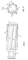
- the cutter illustrated there comprises a hollow cylindrical shell portion, designated generally by reference character 11, having at one end a mounting shank or stem 13 and, at the other end, a plurality of axially projecting cutting teeth.
- the cutting teeth are even in number and are of two types designated, respectively, by reference characters 15 and 17.
- the teeth are separated by gullets 16 and 18.
- Flutes 21, having a slight helical twist, are provided for feeding chips away from the teeth 15 and 17. Only the distal end of the cutter body is of full diameter and the portions of the shell between the flutes away from the cutting end are of slightly reduced diameter, i.e. the portions of the shell to the left of the shoulders indicated by reference character 23 in Fig. 1.
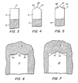
- each of the alternate cutting teeth 17 provides a single straight cutting edge, this edge being designated by reference character 31.
- the cutting edges 31 have a slight negative rake with respect to the radial, e.g. ten degrees, so that the line of the cutting edge does not pass through the axis of the cutter.
- the rake is designated by "A" on Fig. 2.
- the cutting edges 31 do, however, essentially lie in a common plane which is perpendicular to the cutter axis.
- each of the intermediate teeth 15 utilizes two cutting edges, an inner cutting edge designated by reference character 33 and an outer cutting edge designated by reference character 35.
- the axially-facing rake faces forming the cutting edges 33 and 35 are separated by a circumferential crest designated by reference character 37.
- the crest 37 projects axially substantially beyond the common plane of the single edged teeth 17, i.e. further away from the stem 13.
- Fig. 5 As may also be seen in Fig.
- the inner cutting edge 33 and the outer cutting edge 35 are inclined, with respect to the cutter axis, away from the crest so that the inner end of each of the inner cutting edges 33 and the outer end of each of the outer cutting edges 35 is substantially behind the common plane of the straight single cutting edges of the teeth 17.
- the cutting edges 33 and 35 may also each have a slight rake with respect to the radial, as illustrated.
- a piece of metal plate being bored is designated generally by reference character 51.
- the groove being indicated by reference character 43 the following tooth, being of the type designated by reference character 17, will cut a pair of chips having cross-sections corresponding to the areas designated by reference characters 45 and 47.
- the next doubly-edged tooth 15 will cut a chip or chips having cross-sections corresponding to the areas designated by reference characters 51 and 53 in Fig. 7. While these areas, in one sense, comprise a single joined region, it has been found that, because of the inclination between the two areas, the material removed will often fracture into two chips corresponding to the separate areas 51 and 53.
- the cutter 11 though it is relatively easy to fabricate, operates to form three or four slender chip types which are relatively easily emptied out of the gullets through the flutes 21.
- cutting can proceed relatively quickly.
- the teeth themselves are relatively strong and not subject to early failure since all the cutting edges are relatively well supported.
- annular hole cutter which generates a multiplicity of slender chips which are easily fed away from the cutting teeth; the cutter does not require the use of a circumferential offset between distinct cutting edges in the same tooth; the cutter provides long life and is sturdy and highly reliable; the cutter is relatively simple and inexpensive to manufacture.
Landscapes
- Engineering & Computer Science (AREA)
- Mechanical Engineering (AREA)
- Drilling Tools (AREA)
Applications Claiming Priority (2)
| Application Number | Priority Date | Filing Date | Title |
|---|---|---|---|
| US10837087A | 1987-10-14 | 1987-10-14 | |
| US108370 | 1993-08-18 |
Publications (1)
| Publication Number | Publication Date |
|---|---|
| EP0313237A1 true EP0313237A1 (de) | 1989-04-26 |
Family
ID=22321825
Family Applications (1)
| Application Number | Title | Priority Date | Filing Date |
|---|---|---|---|
| EP88309365A Withdrawn EP0313237A1 (de) | 1987-10-14 | 1988-10-07 | Hohlbohrer |
Country Status (2)
| Country | Link |
|---|---|
| EP (1) | EP0313237A1 (de) |
| JP (1) | JPH01199710A (de) |
Cited By (5)
| Publication number | Priority date | Publication date | Assignee | Title |
|---|---|---|---|---|
| US5842820A (en) * | 1997-01-23 | 1998-12-01 | Lee Valley Tools Ltd. | Cutter for use in forming dowels, plugs, and tenons |
| US6004082A (en) * | 1998-03-03 | 1999-12-21 | Lee Valley Tools Ltd. | Tenon cutter |
| US6099214A (en) * | 1997-01-23 | 2000-08-08 | Lee Valley Tools, Ltd. | Cutter for use in forming dowels, plugs, and tenons |
| US6099211A (en) * | 1998-03-03 | 2000-08-08 | Lee Valley Tools Ltd. | Miniature tenon cutter |
| US6263929B1 (en) | 1999-08-26 | 2001-07-24 | Lee Valley Tools Ltd. | Dowel maker |
Families Citing this family (1)
| Publication number | Priority date | Publication date | Assignee | Title |
|---|---|---|---|---|
| JP3780024B2 (ja) * | 1996-01-29 | 2006-05-31 | 大見工業株式会社 | ホールカッタ |
Citations (4)
| Publication number | Priority date | Publication date | Assignee | Title |
|---|---|---|---|---|
| USRE28416E (en) * | 1971-12-29 | 1975-05-06 | Annular hole cutter | |
| GB2146923A (en) * | 1983-09-26 | 1985-05-01 | Jancy Eng | Center free drill |
| GB2167983A (en) * | 1984-11-01 | 1986-06-11 | Nitto Kohki Co | Annular hole cutter |
| EP0229402A1 (de) * | 1986-01-16 | 1987-07-22 | Walker-Hagou B.V. | Flachschneider |
-
1988
- 1988-10-07 EP EP88309365A patent/EP0313237A1/de not_active Withdrawn
- 1988-10-14 JP JP63259250A patent/JPH01199710A/ja active Pending
Patent Citations (4)
| Publication number | Priority date | Publication date | Assignee | Title |
|---|---|---|---|---|
| USRE28416E (en) * | 1971-12-29 | 1975-05-06 | Annular hole cutter | |
| GB2146923A (en) * | 1983-09-26 | 1985-05-01 | Jancy Eng | Center free drill |
| GB2167983A (en) * | 1984-11-01 | 1986-06-11 | Nitto Kohki Co | Annular hole cutter |
| EP0229402A1 (de) * | 1986-01-16 | 1987-07-22 | Walker-Hagou B.V. | Flachschneider |
Non-Patent Citations (1)
| Title |
|---|
| PATENT ABSTRACTS OF JAPAN * |
Cited By (5)
| Publication number | Priority date | Publication date | Assignee | Title |
|---|---|---|---|---|
| US5842820A (en) * | 1997-01-23 | 1998-12-01 | Lee Valley Tools Ltd. | Cutter for use in forming dowels, plugs, and tenons |
| US6099214A (en) * | 1997-01-23 | 2000-08-08 | Lee Valley Tools, Ltd. | Cutter for use in forming dowels, plugs, and tenons |
| US6004082A (en) * | 1998-03-03 | 1999-12-21 | Lee Valley Tools Ltd. | Tenon cutter |
| US6099211A (en) * | 1998-03-03 | 2000-08-08 | Lee Valley Tools Ltd. | Miniature tenon cutter |
| US6263929B1 (en) | 1999-08-26 | 2001-07-24 | Lee Valley Tools Ltd. | Dowel maker |
Also Published As
| Publication number | Publication date |
|---|---|
| JPH01199710A (ja) | 1989-08-11 |
Similar Documents
| Publication | Publication Date | Title |
|---|---|---|
| EP0174089B1 (de) | Abgestufter Bohrer | |
| US6132149A (en) | Twist drills | |
| US4767245A (en) | Annular hole cutter | |
| US4507028A (en) | Combined drill and reamer | |
| US6739809B2 (en) | Cutting point for a drill | |
| US4586857A (en) | Hole cutter | |
| KR930003348Y1 (ko) | 인서어트 천공기 | |
| JPH04102713U (ja) | 多数インサートエンドミル | |
| KR100554908B1 (ko) | 드릴날 부착식 나사절삭 밀링커터 | |
| CN100423888C (zh) | 用于切屑去除的刀具 | |
| EP2277648A1 (de) | Bohrkopf zum tiefbohren | |
| US5944460A (en) | Annular hole cutter | |
| EP0313237A1 (de) | Hohlbohrer | |
| GB2080711A (en) | Annular cutter | |
| GB2182588A (en) | Annular hole cutter | |
| JP2005177891A (ja) | ドリル | |
| JPH08257816A (ja) | テーパ孔用工具 | |
| JP2878443B2 (ja) | スローアウェイ式エンドミル | |
| JP2571499Y2 (ja) | ドリル刃付きねじ切りフライス | |
| US20240391007A1 (en) | Thread milling cutting tool | |
| JPS63185507A (ja) | ドリル | |
| JPS6125935Y2 (de) | ||
| JPH11235606A (ja) | スローアウェイチップおよび該スローアウェイチップを装着したスローアウェイ式穴明け工具 | |
| JP2005138258A (ja) | ドリル | |
| JPH0522682U (ja) | リングビツト |
Legal Events
| Date | Code | Title | Description |
|---|---|---|---|
| PUAI | Public reference made under article 153(3) epc to a published international application that has entered the european phase |
Free format text: ORIGINAL CODE: 0009012 |
|
| AK | Designated contracting states |
Kind code of ref document: A1 Designated state(s): DE FR GB IT NL |
|
| STAA | Information on the status of an ep patent application or granted ep patent |
Free format text: STATUS: THE APPLICATION IS DEEMED TO BE WITHDRAWN |
|
| 18D | Application deemed to be withdrawn |
Effective date: 19891027 |