EP0313253A2 - Douille à languettes de contact rapportées - Google Patents
Douille à languettes de contact rapportées Download PDFInfo
- Publication number
- EP0313253A2 EP0313253A2 EP88309497A EP88309497A EP0313253A2 EP 0313253 A2 EP0313253 A2 EP 0313253A2 EP 88309497 A EP88309497 A EP 88309497A EP 88309497 A EP88309497 A EP 88309497A EP 0313253 A2 EP0313253 A2 EP 0313253A2
- Authority
- EP
- European Patent Office
- Prior art keywords
- box
- male tab
- tab terminal
- receptacle
- terminal
- Prior art date
- Legal status (The legal status is an assumption and is not a legal conclusion. Google has not performed a legal analysis and makes no representation as to the accuracy of the status listed.)
- Withdrawn
Links
Images

Classifications
-
- H—ELECTRICITY
- H01—ELECTRIC ELEMENTS
- H01R—ELECTRICALLY-CONDUCTIVE CONNECTIONS; STRUCTURAL ASSOCIATIONS OF A PLURALITY OF MUTUALLY-INSULATED ELECTRICAL CONNECTING ELEMENTS; COUPLING DEVICES; CURRENT COLLECTORS
- H01R9/00—Structural associations of a plurality of mutually-insulated electrical connecting elements, e.g. terminal strips or terminal blocks; Terminals or binding posts mounted upon a base or in a case; Bases therefor
- H01R9/22—Bases, e.g. strip, block, panel
-
- H—ELECTRICITY
- H01—ELECTRIC ELEMENTS
- H01R—ELECTRICALLY-CONDUCTIVE CONNECTIONS; STRUCTURAL ASSOCIATIONS OF A PLURALITY OF MUTUALLY-INSULATED ELECTRICAL CONNECTING ELEMENTS; COUPLING DEVICES; CURRENT COLLECTORS
- H01R13/00—Details of coupling devices of the kinds covered by groups H01R12/70 or H01R24/00 - H01R33/00
- H01R13/02—Contact members
- H01R13/10—Sockets for co-operation with pins or blades
- H01R13/11—Resilient sockets
- H01R13/113—Resilient sockets co-operating with pins or blades having a rectangular transverse section
Definitions
- This invention relates generally to electrical terminals and more particularly to a fabricated tab receptacle terminal which is capable of establishing improved electrical contact with a male tab terminal by utilizing fixed beams on both sides of an inserted male tab terminal.
- Tab receptacle terminals of the tab receptacle type are in common use in appliances, automobiles, etc. and are an essential component of many products.
- Tab receptacle terminals in the prior art include springs to grip at least one side of the male tab terminal upon insertion.
- the spring member limits the amount of current that the tab terminal connection can carry.
- resistance heating in the spring members causes a weakening in the spring member and limits the ampacity at which the terminals can be used.
- Improved ampacity is achieved by providing fixed beam contact between the tab terminal and receptacle terminal.
- An improved tab receptacle terminal having a closed continuous wall which increases the current carrying capability of the receptacle is disclosed in U.S. patent application Serial No. 916,950, commonly assigned.
- This terminal utilizes an integral spring formed in the top of the closed continuous wall box and fixed beams in the bottom of the box.
- the fixed beams are the prime current carrying members.
- the present invention utilizes fixed beams on both sides of the male tab terminal thus further improving the ampacity of the terminal.
- a disadvantage in prior art receptacle terminal designs occurs where contact of the receptacle terminal with the inserted male tab terminal creates a pivot point allowing relative rocking of the terminal components. This condition causes a type of fretting corrosion whereby oxides of tin inhibit contact between terminal elements. This increases contact resistance and creates increased resistance heating.
- the receptacle of this invention may be used in a discrete application, in multiple connectors, or any other fabricated array that might be designed, e.g., a bus bar or lead frame.
- the tab receptacle terminal of this invention is fabricated by bending a single sheet of metal. Interlocking tabs are formed on the ends of the single sheet of metal from which the tab receptacle is formed to maintain the box in its desired rectangular form.
- the tab receptacle is a rectangular receptacle box having a closed continuous wall forming an end opening through which a male tab terminal is inserted.
- the receptacle box has a bottom, a top, and upright sides. There are fixed beams formed in the top that extend toward the bottom which engage one side of an inserted male tab terminal.
- a cantilever supported movable beam is formed by folding a portion of the terminal into the interior of the box for contact with the other side of the male tab terminal.
- This beam member includes a front end portion located adjacent to the end opening, a middle portion, and a rear portion attached to the box. The rear portion of the movable beam is bent upward towards the top of the box, the middle portion is bent almost parallel to the bottom, and the front end portion of the beam is bend downward toward the bottom.
- transverse raised ridge Between the front end portion of the beam and middle portion is a transverse raised ridge positioned to make contact with the under side of an inserted male tab terminal.
- a similar transverse raised ridge is also provided at the transition between the middle portion and the rear portion of the movable beam.
- the bottom of the box has an integral flap at the end opening which is bent toward and into the opening at an acute angle, overlapping and limiting the motion of the movable beam and making the beam fixed when the male tab terminal is inserted within the box. This provides fixed beam contact between the ridges on the beam and the under side of the male tab terminal and between the fixed beams in the top and the upper side of the inserted male tab terminal.
- This fixed beam contact on both sides of the male tab terminal enhances the current carrying capability of the connector, increases the rigidity with which the male tab terminal is held inside the receptacle, and minimizes the amount of fretting corrosion that can occur between the contact surfaces.
- An additional flap in the top of the receptacle box at the end opening which is bent toward and into the box at an acute angle guides insertion of the male tab terminal.
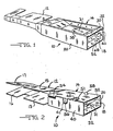
- the tab receptacle terminal having fixed beam contacts of this invention is illustrated in perspective in Figures 1 and 2.
- the tab receptacle terminal 10 includes receptacle box 14 and integral wire clamping portion 12. Flaps 15 and 13 are used to crimp over and attach a connecting wire (not shown). Flaps 16 and 17 are correspondingly used to crimp onto the insulation on the connecting wire (not shown).
- the wire connecting section 12 is integral with box side 20 and a portion of the top 30 of receptacle box 14 and a portion of the bottom 50 of receptacle box 14.
- the receptacle box 14 is generally comprised of sides 20 and 40 and top 30 and bottom 50. As shown in Figure 1, the top 30 has an indented region 31 generally rectangular in shape. End opening 18 allows for male tab terminal insertion into the tab receptacle box 14. Flap 32 at the end opening portion of top 30 is bent downward and inward into opening 18 at an acute angle. A corresponding flap 52 on the bottom 50 is bent into the receptacle box 14 at an acute angle. The combination of flaps 32 and 52 guide insertion of a male tab terminal 11 as shown in Figure 4.
- a cantilever supported movable beam member 60 extends inside the receptacle box 14 from the rear portion towards end opening 18.
- Cantilever beam member 60 is formed by bending a metal portion 62 over the bottom 50 at bend 54 such that the base portion of the beam member 60 lies adjacent and against bottom side 50.
- the rear portion 64 is bent upward towards the top 30.
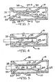
- Middle portion 66 is bent generally in the direction of bottom 50. As can be seen in Figure 3 and 4, a transverse raised ridge 65 projects toward the top 30.
- transverse raised ridge 67 projects toward the top 30 at the transition between middle portion 66 and end portion 68. End portion 68 is bent downward toward bottom 50. Longitudinal ribs 34 and 36 clearly shown in Figures 3 and 5 project downward from the recessed portion 31 of top 30. Cantilever supported beam member 60 is biased toward top 30 and is restrained at end portion 68 by contact with guiding flap 52.
- a corresponding guiding flap 32 in the top 30 provides symmetrical guidance as a mating tab terminal is inserted into the receptacle as shown in Figures 4 and 5.
- cantilever movable beam member 60 is deflected until end portion 68 contacts bottom 50. Further insertion deflects the end of end portion 68 into corner 53 formed between flap 52 and bottom 50 thus terminating any further deflection of member 60.
- transverse ridges 65 and 67 becoming transversed fixed beams contacting the underside of male tab terminal 11 while longitudinal fixed beams 34 and 36 contact the upper side of inserted male tab terminal 11.
- Figure 6 shows the relationship between transverse cantilevered beam member 65 and longitudinal fixed beams 34 and 36.
- the tab receptacle in this embodiment therefore presents to the male tab terminal four fixed beam contact surface lines represented by fixed beams 34, 36, 65, and 67.
- the pairs of fixed beams 34, 36 and 65, 67 thus formed preclude rocking of male tab terminal 11 within receptacle box 14 and provide a distributed firm grip on inserted male tab terminal 11.
- the contact members are fixed beams, increased ampacity is achieved for a tab receptacle of a given size.
- the tab receptacle terminal is fabricated by bending a single sheet of metal.
- a sheet metal stamping prior to bending is shown in Figure 7. It can be seen that cantilever supported movable beam member 60 is integrally attached to bottom 50. As shown in Figure 7 longitudinal fixed beams 34 and 36 are already formed in the top 30. Similarly, depressed portions 41 and 51 for receiving tabs 56 and 42 respectively are preformed in side 40 and bottom 50.
- the receptacle terminal of the present invention may be used with male tab terminals of different thickness as illustrated in Figure 4.
- a male tab terminal with a thin blade will contact the fixed beams 34 and 36 and the first transverse raised ridge 67 upon insertion.
- Ridge 67 is positioned interior to the front end of beams 34 and 36 thereby maintaining rigid contact of the tab terminal with the beams.
- end portion 68 of beam 60 is not wedged into corner 53 thus limiting the ampacity of this combination to a lesser value than that of figure 5.
- short male tab terminals are readily accomodated by the receptacle terminal of the present invention so long as the tab terminal can be inserted past transverse ridge 67.
Landscapes
- Connector Housings Or Holding Contact Members (AREA)
- Coupling Device And Connection With Printed Circuit (AREA)
- Manufacturing Of Electrical Connectors (AREA)
Applications Claiming Priority (2)
| Application Number | Priority Date | Filing Date | Title |
|---|---|---|---|
| US11022587A | 1987-10-19 | 1987-10-19 | |
| US110225 | 1987-10-19 |
Publications (2)
| Publication Number | Publication Date |
|---|---|
| EP0313253A2 true EP0313253A2 (fr) | 1989-04-26 |
| EP0313253A3 EP0313253A3 (fr) | 1990-05-23 |
Family
ID=22331886
Family Applications (1)
| Application Number | Title | Priority Date | Filing Date |
|---|---|---|---|
| EP88309497A Withdrawn EP0313253A3 (fr) | 1987-10-19 | 1988-10-11 | Douille à languettes de contact rapportées |
Country Status (3)
| Country | Link |
|---|---|
| EP (1) | EP0313253A3 (fr) |
| JP (1) | JPH01202328A (fr) |
| KR (1) | KR890007455A (fr) |
Cited By (17)
| Publication number | Priority date | Publication date | Assignee | Title |
|---|---|---|---|---|
| GB2225183A (en) * | 1988-10-21 | 1990-05-23 | Amp Inc | Electric socket terminal |
| FR2647602A1 (fr) * | 1989-05-25 | 1990-11-30 | Amp France | Contact femelle |
| EP0463608A3 (en) * | 1990-06-27 | 1992-09-09 | Yazaki Corporation | Joint terminal |
| US5147230A (en) * | 1991-12-19 | 1992-09-15 | General Motors Corporation | Two piece electrical female terminal |
| US5427552A (en) * | 1993-11-22 | 1995-06-27 | Chrysler Corporation | Electrical terminal and method of fabricating same |
| EP0673082A4 (fr) * | 1993-10-01 | 1996-02-28 | Ryosei Electro Circuit Sys Ltd | Borne de jonction et son procede de fabrication. |
| GB2298320A (en) * | 1995-02-21 | 1996-08-28 | Mecanismos Aux Ind | A terminal |
| GB2298321A (en) * | 1995-02-21 | 1996-08-28 | Mecanismos Aux Ind | An electrical terminal |
| EP0755096A1 (fr) * | 1995-07-18 | 1997-01-22 | Sumitomo Wiring Systems, Ltd. | Borne métallique femelle et procédé de fabrication |
| FR2749442A1 (fr) * | 1996-06-03 | 1997-12-05 | Framatome Connectors Int | Borne de contact electrique femelle a structure reforcee |
| GB2315929A (en) * | 1996-07-31 | 1998-02-11 | Whitaker Corp | Low insertion force receptacle contact |
| ES2114467A1 (es) * | 1994-12-01 | 1998-05-16 | Bosch Gmbh Robert | Conexion electrica por enchufe. |
| EP1160924A1 (fr) * | 2000-05-30 | 2001-12-05 | Société Anonyme SYLEA | Dispositif de liaison électrique pour organe de contact électrique mâle et élément de boítier destiné à recevoir un tel dispositif |
| KR100498791B1 (ko) * | 1996-06-03 | 2005-12-26 | 프라마또므 꼬넥또 엥떼르나시오날 | 제어된 접점 압력을 가지는 암형 전기 접점 단자 |
| WO2012069499A1 (fr) * | 2010-11-23 | 2012-05-31 | Fci Automotive Holding | Borne électrique |
| EP2479848A1 (fr) * | 2003-06-18 | 2012-07-25 | Mitsubishi Cable Industries, Ltd. | Borne de connexion |
| EP2642598A1 (fr) * | 2012-03-19 | 2013-09-25 | Yazaki Europe Ltd | Terminal électrique |
Families Citing this family (5)
| Publication number | Priority date | Publication date | Assignee | Title |
|---|---|---|---|---|
| JP2583147Y2 (ja) * | 1991-06-06 | 1998-10-15 | 東洋電装株式会社 | リセプタクル端子 |
| DE60312848T2 (de) | 2002-05-17 | 2007-09-06 | Mitsubishi Cable Industries, Ltd. | Verbindungsanschluss |
| JP4076509B2 (ja) * | 2004-01-23 | 2008-04-16 | 矢崎総業株式会社 | 雌端子 |
| JP6080821B2 (ja) | 2014-09-17 | 2017-02-15 | 矢崎総業株式会社 | 端子 |
| JP6979314B2 (ja) * | 2017-09-20 | 2021-12-08 | 日本航空電子工業株式会社 | コネクタ |
Family Cites Families (2)
| Publication number | Priority date | Publication date | Assignee | Title |
|---|---|---|---|---|
| NL6509459A (fr) * | 1965-07-21 | 1967-01-23 | ||
| FR2412180A1 (fr) * | 1977-12-16 | 1979-07-13 | Labinal | Element femelle de contacts electriques |
-
1988
- 1988-10-11 EP EP88309497A patent/EP0313253A3/fr not_active Withdrawn
- 1988-10-18 KR KR1019880013582A patent/KR890007455A/ko not_active Withdrawn
- 1988-10-18 JP JP63262667A patent/JPH01202328A/ja active Pending
Cited By (27)
| Publication number | Priority date | Publication date | Assignee | Title |
|---|---|---|---|---|
| GB2225183A (en) * | 1988-10-21 | 1990-05-23 | Amp Inc | Electric socket terminal |
| GB2225183B (en) * | 1988-10-21 | 1992-09-16 | Amp Inc | Electrical tab receptacle |
| FR2647602A1 (fr) * | 1989-05-25 | 1990-11-30 | Amp France | Contact femelle |
| EP0463608A3 (en) * | 1990-06-27 | 1992-09-09 | Yazaki Corporation | Joint terminal |
| US5147230A (en) * | 1991-12-19 | 1992-09-15 | General Motors Corporation | Two piece electrical female terminal |
| EP0673082A4 (fr) * | 1993-10-01 | 1996-02-28 | Ryosei Electro Circuit Sys Ltd | Borne de jonction et son procede de fabrication. |
| US5551150A (en) * | 1993-11-22 | 1996-09-03 | Chrysler Corporation | Method of fabricating an electrical terminal |
| US5427552A (en) * | 1993-11-22 | 1995-06-27 | Chrysler Corporation | Electrical terminal and method of fabricating same |
| ES2114467A1 (es) * | 1994-12-01 | 1998-05-16 | Bosch Gmbh Robert | Conexion electrica por enchufe. |
| GB2298320A (en) * | 1995-02-21 | 1996-08-28 | Mecanismos Aux Ind | A terminal |
| GB2298321A (en) * | 1995-02-21 | 1996-08-28 | Mecanismos Aux Ind | An electrical terminal |
| GB2298321B (en) * | 1995-02-21 | 1999-06-02 | Mecanismos Aux Ind | An electrical terminal |
| GB2298320B (en) * | 1995-02-21 | 1999-05-19 | Mecanismos Aux Ind | A terminal |
| EP0755096A1 (fr) * | 1995-07-18 | 1997-01-22 | Sumitomo Wiring Systems, Ltd. | Borne métallique femelle et procédé de fabrication |
| EP0812035A1 (fr) * | 1996-06-03 | 1997-12-10 | Framatome Connectors International | Borne de contact électrique femelle à structure renforcée |
| FR2749442A1 (fr) * | 1996-06-03 | 1997-12-05 | Framatome Connectors Int | Borne de contact electrique femelle a structure reforcee |
| US5951339A (en) * | 1996-06-03 | 1999-09-14 | Framatome Connectors International | Female electrical contact terminal with a reinforced structure |
| KR100498791B1 (ko) * | 1996-06-03 | 2005-12-26 | 프라마또므 꼬넥또 엥떼르나시오날 | 제어된 접점 압력을 가지는 암형 전기 접점 단자 |
| GB2315929A (en) * | 1996-07-31 | 1998-02-11 | Whitaker Corp | Low insertion force receptacle contact |
| GB2315929B (en) * | 1996-07-31 | 2000-08-16 | Whitaker Corp | Low insertion force receptacle contact |
| EP1160924A1 (fr) * | 2000-05-30 | 2001-12-05 | Société Anonyme SYLEA | Dispositif de liaison électrique pour organe de contact électrique mâle et élément de boítier destiné à recevoir un tel dispositif |
| FR2809872A1 (fr) * | 2000-05-30 | 2001-12-07 | Sylea | Dispositif de liaison electrique pour organe de contact electrique male et element de boitier destine a recevoir un tel dispositif |
| US6409554B2 (en) | 2000-05-30 | 2002-06-25 | Sylea | Electrical connection device for directly joining a conductor to a male electrical contact member |
| EP2479848A1 (fr) * | 2003-06-18 | 2012-07-25 | Mitsubishi Cable Industries, Ltd. | Borne de connexion |
| WO2012069499A1 (fr) * | 2010-11-23 | 2012-05-31 | Fci Automotive Holding | Borne électrique |
| EP2642598A1 (fr) * | 2012-03-19 | 2013-09-25 | Yazaki Europe Ltd | Terminal électrique |
| US8858274B2 (en) | 2012-03-19 | 2014-10-14 | Yazaki Europe Ltd. | Electric terminal |
Also Published As
| Publication number | Publication date |
|---|---|
| KR890007455A (ko) | 1989-06-19 |
| JPH01202328A (ja) | 1989-08-15 |
| EP0313253A3 (fr) | 1990-05-23 |
Similar Documents
| Publication | Publication Date | Title |
|---|---|---|
| US4919628A (en) | Tab receptacle with fixed beam contacts | |
| EP0313253A2 (fr) | Douille à languettes de contact rapportées | |
| US5611717A (en) | Miniature anti-fretting receptacle terminal | |
| EP0463608B1 (fr) | Terminal de jonction | |
| US5681190A (en) | Torsional blade receptacle | |
| US5338229A (en) | Electrical contact | |
| KR100244733B1 (ko) | 전기콘택트 | |
| EP0750799B1 (fr) | Contact electrique | |
| EP0688065B1 (fr) | Casse électrique | |
| US5480320A (en) | Electrical connection element | |
| US6077131A (en) | Male terminal | |
| US5541365A (en) | Beam Welding Terminal Structure | |
| US7686662B2 (en) | Electrical connector assembly | |
| US20080188144A1 (en) | Sealed orientation feature for a terminal | |
| JPH1092497A (ja) | 電気端子 | |
| GB2228150A (en) | Device for interconnecting electrical terminals | |
| US20050054247A1 (en) | Female terminal for a flat male terminal | |
| EP0693798B1 (fr) | Ensemble métallique pour contact mâle | |
| US5462459A (en) | Spring-type electrical receptacle | |
| EP0977317A2 (fr) | Borne électrique á réceptacle | |
| EP0687033A2 (fr) | Borne de prise de courants forts | |
| US6790100B2 (en) | Female terminal fitting | |
| JPH0927368A (ja) | 雌型端子 | |
| US5344348A (en) | Electrical terminal | |
| EP0727843B1 (fr) | Douille asymétrique de contact électrique |
Legal Events
| Date | Code | Title | Description |
|---|---|---|---|
| PUAI | Public reference made under article 153(3) epc to a published international application that has entered the european phase |
Free format text: ORIGINAL CODE: 0009012 |
|
| AK | Designated contracting states |
Kind code of ref document: A2 Designated state(s): DE ES FR GB IT SE |
|
| PUAL | Search report despatched |
Free format text: ORIGINAL CODE: 0009013 |
|
| AK | Designated contracting states |
Kind code of ref document: A3 Designated state(s): DE ES FR GB IT SE |
|
| 17P | Request for examination filed |
Effective date: 19900522 |
|
| STAA | Information on the status of an ep patent application or granted ep patent |
Free format text: STATUS: THE APPLICATION HAS BEEN WITHDRAWN |
|
| 18W | Application withdrawn |
Withdrawal date: 19910426 |