EP2642598A1 - Terminal électrique - Google Patents
Terminal électrique Download PDFInfo
- Publication number
- EP2642598A1 EP2642598A1 EP12160222.1A EP12160222A EP2642598A1 EP 2642598 A1 EP2642598 A1 EP 2642598A1 EP 12160222 A EP12160222 A EP 12160222A EP 2642598 A1 EP2642598 A1 EP 2642598A1
- Authority
- EP
- European Patent Office
- Prior art keywords
- connecting ends
- electric terminal
- hood
- sheet
- terminal according
- Prior art date
- Legal status (The legal status is an assumption and is not a legal conclusion. Google has not performed a legal analysis and makes no representation as to the accuracy of the status listed.)
- Granted
Links
Images

Classifications
-
- H—ELECTRICITY
- H01—ELECTRIC ELEMENTS
- H01R—ELECTRICALLY-CONDUCTIVE CONNECTIONS; STRUCTURAL ASSOCIATIONS OF A PLURALITY OF MUTUALLY-INSULATED ELECTRICAL CONNECTING ELEMENTS; COUPLING DEVICES; CURRENT COLLECTORS
- H01R4/00—Electrically-conductive connections between two or more conductive members in direct contact, i.e. touching one another; Means for effecting or maintaining such contact; Electrically-conductive connections having two or more spaced connecting locations for conductors and using contact members penetrating insulation
- H01R4/22—End caps, i.e. of insulating or conductive material for covering or maintaining connections between wires entering the cap from the same end
-
- H—ELECTRICITY
- H01—ELECTRIC ELEMENTS
- H01R—ELECTRICALLY-CONDUCTIVE CONNECTIONS; STRUCTURAL ASSOCIATIONS OF A PLURALITY OF MUTUALLY-INSULATED ELECTRICAL CONNECTING ELEMENTS; COUPLING DEVICES; CURRENT COLLECTORS
- H01R13/00—Details of coupling devices of the kinds covered by groups H01R12/70 or H01R24/00 - H01R33/00
- H01R13/02—Contact members
- H01R13/15—Pins, blades or sockets having separate spring member for producing or increasing contact pressure
- H01R13/187—Pins, blades or sockets having separate spring member for producing or increasing contact pressure with spring member in the socket
-
- H—ELECTRICITY
- H01—ELECTRIC ELEMENTS
- H01R—ELECTRICALLY-CONDUCTIVE CONNECTIONS; STRUCTURAL ASSOCIATIONS OF A PLURALITY OF MUTUALLY-INSULATED ELECTRICAL CONNECTING ELEMENTS; COUPLING DEVICES; CURRENT COLLECTORS
- H01R13/00—Details of coupling devices of the kinds covered by groups H01R12/70 or H01R24/00 - H01R33/00
- H01R13/02—Contact members
- H01R13/10—Sockets for co-operation with pins or blades
- H01R13/11—Resilient sockets
-
- H—ELECTRICITY
- H01—ELECTRIC ELEMENTS
- H01R—ELECTRICALLY-CONDUCTIVE CONNECTIONS; STRUCTURAL ASSOCIATIONS OF A PLURALITY OF MUTUALLY-INSULATED ELECTRICAL CONNECTING ELEMENTS; COUPLING DEVICES; CURRENT COLLECTORS
- H01R13/00—Details of coupling devices of the kinds covered by groups H01R12/70 or H01R24/00 - H01R33/00
- H01R13/02—Contact members
- H01R13/15—Pins, blades or sockets having separate spring member for producing or increasing contact pressure
- H01R13/18—Pins, blades or sockets having separate spring member for producing or increasing contact pressure with the spring member surrounding the socket
-
- H—ELECTRICITY
- H01—ELECTRIC ELEMENTS
- H01R—ELECTRICALLY-CONDUCTIVE CONNECTIONS; STRUCTURAL ASSOCIATIONS OF A PLURALITY OF MUTUALLY-INSULATED ELECTRICAL CONNECTING ELEMENTS; COUPLING DEVICES; CURRENT COLLECTORS
- H01R13/00—Details of coupling devices of the kinds covered by groups H01R12/70 or H01R24/00 - H01R33/00
- H01R13/02—Contact members
- H01R13/10—Sockets for co-operation with pins or blades
- H01R13/11—Resilient sockets
- H01R13/114—Resilient sockets co-operating with pins or blades having a square transverse section
-
- H—ELECTRICITY
- H01—ELECTRIC ELEMENTS
- H01R—ELECTRICALLY-CONDUCTIVE CONNECTIONS; STRUCTURAL ASSOCIATIONS OF A PLURALITY OF MUTUALLY-INSULATED ELECTRICAL CONNECTING ELEMENTS; COUPLING DEVICES; CURRENT COLLECTORS
- H01R4/00—Electrically-conductive connections between two or more conductive members in direct contact, i.e. touching one another; Means for effecting or maintaining such contact; Electrically-conductive connections having two or more spaced connecting locations for conductors and using contact members penetrating insulation
- H01R4/10—Electrically-conductive connections between two or more conductive members in direct contact, i.e. touching one another; Means for effecting or maintaining such contact; Electrically-conductive connections having two or more spaced connecting locations for conductors and using contact members penetrating insulation effected solely by twisting, wrapping, bending, crimping, or other permanent deformation
- H01R4/18—Electrically-conductive connections between two or more conductive members in direct contact, i.e. touching one another; Means for effecting or maintaining such contact; Electrically-conductive connections having two or more spaced connecting locations for conductors and using contact members penetrating insulation effected solely by twisting, wrapping, bending, crimping, or other permanent deformation by crimping
- H01R4/183—Electrically-conductive connections between two or more conductive members in direct contact, i.e. touching one another; Means for effecting or maintaining such contact; Electrically-conductive connections having two or more spaced connecting locations for conductors and using contact members penetrating insulation effected solely by twisting, wrapping, bending, crimping, or other permanent deformation by crimping for cylindrical elongated bodies, e.g. cables having circular cross-section
- H01R4/184—Electrically-conductive connections between two or more conductive members in direct contact, i.e. touching one another; Means for effecting or maintaining such contact; Electrically-conductive connections having two or more spaced connecting locations for conductors and using contact members penetrating insulation effected solely by twisting, wrapping, bending, crimping, or other permanent deformation by crimping for cylindrical elongated bodies, e.g. cables having circular cross-section comprising a U-shaped wire-receiving portion
- H01R4/185—Electrically-conductive connections between two or more conductive members in direct contact, i.e. touching one another; Means for effecting or maintaining such contact; Electrically-conductive connections having two or more spaced connecting locations for conductors and using contact members penetrating insulation effected solely by twisting, wrapping, bending, crimping, or other permanent deformation by crimping for cylindrical elongated bodies, e.g. cables having circular cross-section comprising a U-shaped wire-receiving portion combined with a U-shaped insulation-receiving portion
-
- H—ELECTRICITY
- H01—ELECTRIC ELEMENTS
- H01R—ELECTRICALLY-CONDUCTIVE CONNECTIONS; STRUCTURAL ASSOCIATIONS OF A PLURALITY OF MUTUALLY-INSULATED ELECTRICAL CONNECTING ELEMENTS; COUPLING DEVICES; CURRENT COLLECTORS
- H01R43/00—Apparatus or processes specially adapted for manufacturing, assembling, maintaining, or repairing of line connectors or current collectors or for joining electric conductors
- H01R43/16—Apparatus or processes specially adapted for manufacturing, assembling, maintaining, or repairing of line connectors or current collectors or for joining electric conductors for manufacturing contact members, e.g. by punching and by bending
Definitions
- the invention relates to an electric terminal comprising a terminal body and a box-shaped hood.
- the hood encloses at least partially the terminal body.
- the hood is bent from a sheet-metal part into the box-shaped design wherein the sheet-metal part has a first connecting end and a second connecting end both being bent towards each other.
- a multitude of such electrical terminals are for example provided in connections, used in motor vehicles on wire harnesses or for connecting electrically operated equipment elements of a motor vehicle.
- Such connectors have housings, in which often in several rows, one on top of another and next to each other cavities are formed, which, respectively, accommodate an electrical terminal.
- a locking element in form of an elastic arm is arranged, which rests with a projection behind a corresponding contour of the terminal and especially its support element, so that the terminal is securely retained against pulling-out from the housing.
- secondary locking means are also provided. Even if pulling forces act on the cable connected to the individual terminals, the electrical terminal should be securely held within the connector housing.
- the sealing of such connectors is important, as for example in the engine compartment of a motor vehicle a moist environment exists. Spray water can enter the area of such a connector. Because of this reason the individual electrical terminals have to be sealed. This can be achieved such, that to each individual electrical terminal a special seal is arranged, which is arranged in a corresponding opening in front of the cavity for the electrical terminal.
- the end of the connector, from which the terminals are inserted into the cavities is provided with a seal, which covers the whole area of all insertion openings and has corresponding insertion openings for respectively one electric terminal, aligned to the individual cavity.
- the electrical terminals are inserted normally after the assembly of the seals into the cavity of the connector, the electrical terminals have to be formed such, that a damage of the seal and thus a place of intrusion for water is prevented.
- EP 1 780 835 B1 describes an electric terminal according to the preamble of claim 1.
- a housing having several cavities, to which respectively a locking arm is arranged, which abuts a projection on an electric terminal.
- the electrical terminal shown there comprises a terminal body having a connection portion with crimping tabs for connecting a cable and a contact portion achieving an electrically conductive contact with a complementary contact pin or contact blade of a counter-terminal.
- the contact portion has elastic contact arms integrally formed to the terminal body.
- the contact portion is enclosed by a box-shaped hood.
- the hood has four walls, forming in cross-section a hollow rectangle.
- the four walls are formed by bending a sheet-metal part into the box-shaped design, wherein the sheet-metal part has two connecting ends each having a connecting edge. The connecting edges of the two connecting ends are bent towards each other forming a seam along the extend of the hood.
- the box-shaped hood is secured by welding point along the seam.
- the hood has a relative smooth surface so that, when inserting such an electric terminal into a cavity of a connector closed by a seal, no damage is produced to the seal.
- the hood is cumbersome to manufacture and necessitates a bending manufacturing step and a welding manufacturing step.
- the connecting ends of the sheet-metal part are form-fittingly connected to each other. Therefore, it is not necessary anymore to secure the two connecting ends to each other by welding.
- the form fitting connection can be achieved only by bending the sheet-metal part. Hence, one of the manufacturing steps according to the prior art, i.e. the welding step, can be avoided.
- the hood has a rectangular cross-section wherein the hood has a top wall, a bottom wall and two side walls.
- the connecting ends are forming one of the side walls.
- the connecting ends comprise at least one first engagement arrangement securing the connecting ends against forces in the plane of the connecting ends. If forces are applied to the hood in directions within the plane of the connecting ends, i.e. in the plane of one wall of the hood, the connecting ends cannot be separated nor moved relative to each other.
- the first engagement arrangement can comprise a tab at one of the two connecting ends and a corresponding recess in the other one of the two connecting ends.
- the tab is form-fittingly arranged within the recess so that no movement of the two connecting ends relative to each other within the plane of the connecting ends is possible.
- the connecting ends may also comprise at least one second engagement arrangement securing the connecting ends against movement in a direction perpendicular to the plane of the connecting ends.
- the second engagement arrangement prevents at least in one direction perpendicular to the plane of the connecting ends a relative movement of the connecting ends to each other. It can also be formed such that a movement in both directions perpendicular to the plane of the connecting ends can be prevented.
- the second engagement arrangement comprises a first contact portion and a second contact portion provided at the first end the second connecting ends, respectively, wherein the two contact portions are overlapping each other.
- the second engagement arrangement is arranged such that the first contact portion is held between the second contact portion and the terminal body. This arrangement provides that the first contact portion cannot move in any direction perpendicular to the plane of the connecting ends.
- the contact portions can be embossed such that the contact portions are thinner than the rest of the sheet-metal part.
- the overlapping contact portions together therefore, may not be thicker than the sheet-metal part.
- This embodiment ensures, that no additional space is necessary for the second engagement arrangement. Further, it realizes a clean and smooth outer surface to avoid damages to a seal.
- other designs may also be possible, such as a bended portion of one of the connecting ends forming a longitudinal recess for accommodating the contact portion of the other connecting end along a seam between the two connecting ends.
- a first engagement arrangement and a second engagement arrangement are provided in order to secure the connecting ends in all directions.
- Preferably two first engagement arrangements are provided wherein one second engagement arrangement is arranged between the two first engagement arrangements.
- further engagement arrangements can be provided.
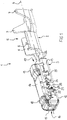
- the electric terminal 1 comprises a terminal body 2 shown as an individual component in Fig. 3 and a hood 3.
- the hood 3 encloses the terminal body 2 on a partial length along the longitudinal axis 4.
- the terminal body 2 is manufactured from a sheet-metal material by means of bending wherein the sheet-metal material has an electrical conductivity, such as cooper or a copper alloy.
- the terminal body 2 comprises a connection portion 5 having two first crimping tabs 6 for connecting an electrical conductor of a cable to the terminal body 2 by means of crimping.
- two second crimping tabs 7 are provided to the right according to Fig. 1 on the connection portion 5.
- the two second crimping tabs 7 can be crimped to an insulation of a cable having the conductor.
- the first crimping tabs 6 and the second crimping tabs 7 start from a bottom portion.
- a contact portion 8 is integrally formed to the connection portion 5 as a hollow rectangular profile, wherein at the end thereof, which is facing away from the connection portion 5, contact arms 9 are attached.
- the contact arms 9 are formed elastically and serve to accommodate and to contact a contact pin or contact blade of a mating electric terminal, and thereby achieving an electrically conductive connection.
- the contact portion 8 ends with an end edge 11.
- two recesses 10 are provided at the connection portion 5, directly following the end edge 11.
- the contact portion 8 and the contact arms 9 of the terminal body 2 are enclosed by the hood 3.
- the hood 3 has also a hollow rectangular cross-section transversally to the longitudinal axis 4. This hollow rectangular cross-section is enclosed by four walls, namely a first wall (bottom wall) 12, a second wall (side wall) 13, following at a right angle thereto, a third wall (top wall) 14 following again thereto, and a fourth wall (side wall) 15 connecting the third wall 14 and the first wall 12.
- the hood 3 has a front end 16 and a rear end 17, wherein the term end is not a definitive end, but an end area or end portion.
- the hood 3 is formed, starting from a sheet-metal part, having a corresponding preform, wherein this is preferably made from a material, which has a higher strength than the terminal body 2.
- a steel is used, i.e. especially a steel having spring characteristics and which is non corrosive.
- the hood 3 has, away from the longitudinal axis 4, two projections, formed by non-cutting working from the base material of the sheet-metal part forming the third wall 14, namely a first projection 18, close to the front end 16, and a second projection 19.
- the second wall 13 is formed from a first connecting end 20 and a second connecting end 21 of the sheet-metal part, wherein these connecting ends abut each other and are arranged in a common plane.
- the hood 3 is provided with two securing lugs 22, which are bent over corresponding parts of the terminal body 2 each engaging one of the recesses 10 of the terminal body 2 in order to secure the hood 3 to the terminal body 2.
- Each first engagement arrangement 23 comprises a tab 25. Integral to the first connecting end 20 and projecting in direction towards the second connecting end 21.
- the tab 25 is accommodated in a recess 26 of the second connecting end 21.
- the tab 25 and the recess 26 are formed complementary.
- the recess 26 has an undercut 27.
- the tab 25 has a corresponding projection 28 engaging the undercut 27 and thereby forming a form-fitting engagement.
- the tab 25 and the recess 26 are formed L-shaped.
- the tab 25 and the recess 26 can also have other shapes providing a form-fitting connection between the two connecting ends 20, 21.
- the tab 25 and the recess 26 could be T-shaped or bird-tail-shaped. Any kind of connection is possible provided that the two connecting ends 20, 21 are secured against a movement relative to each other in the plane of the second wall 13.
- the second engagement arrangement 24 has a first contact portion 29 being part of the first connecting end 20 and a second contact portion 30 being part of the second connecting end 21.
- the second engagement arrangement 24 is depicted in figure 2 .
- the first contact portion 29 is embossed (flattened) in a direction perpendicular to the plane of a second wall 13 hereby forming a recess 31 facing the second connecting end 21.
- a second contact portion 30 is also embossed (flattened) such that a recess 32 is formed facing the first connecting end 20. Since both contact portions 29, 30 are arranged overlapping each other the second contact portion 30 is accommodated in the first recess 31 of the first connecting portion 29 and vice versa, i.e.
- the first contact portion 29 is accommodated in a second recess 32 of the second contact portion 30.
- the contact portions 29, 30 have a thickness such that the overlapping contact portions 29, 30 together have approximately the same thickness as the rest of the sheet-metal part forming the hood 3.
- the second engagement arrangement 24 can also have different designs as long as the contact portions 29, 30 are arranged in an overlapping manor. It can also be provided that the contact portions 29, 30 each have the same thickness as the sheet-metal parts.
- one of the connecting ends 20 can be bent in an S-shape such that it forms a recess for the other connecting end.
Landscapes
- Connector Housings Or Holding Contact Members (AREA)
- Connections Effected By Soldering, Adhesion, Or Permanent Deformation (AREA)
- Manufacturing Of Electrical Connectors (AREA)
- Connections Arranged To Contact A Plurality Of Conductors (AREA)
Priority Applications (5)
| Application Number | Priority Date | Filing Date | Title |
|---|---|---|---|
| EP12160222.1A EP2642598B1 (fr) | 2012-03-19 | 2012-03-19 | Terminal électrique |
| US13/727,824 US8858274B2 (en) | 2012-03-19 | 2012-12-27 | Electric terminal |
| JP2013037566A JP5896531B2 (ja) | 2012-03-19 | 2013-02-27 | 端子 |
| CN201310075543.5A CN103367956B (zh) | 2012-03-19 | 2013-03-08 | 电端子 |
| MX2013002962A MX2013002962A (es) | 2012-03-19 | 2013-03-15 | Terminal electrica. |
Applications Claiming Priority (1)
| Application Number | Priority Date | Filing Date | Title |
|---|---|---|---|
| EP12160222.1A EP2642598B1 (fr) | 2012-03-19 | 2012-03-19 | Terminal électrique |
Publications (2)
| Publication Number | Publication Date |
|---|---|
| EP2642598A1 true EP2642598A1 (fr) | 2013-09-25 |
| EP2642598B1 EP2642598B1 (fr) | 2017-09-13 |
Family
ID=45819141
Family Applications (1)
| Application Number | Title | Priority Date | Filing Date |
|---|---|---|---|
| EP12160222.1A Active EP2642598B1 (fr) | 2012-03-19 | 2012-03-19 | Terminal électrique |
Country Status (5)
| Country | Link |
|---|---|
| US (1) | US8858274B2 (fr) |
| EP (1) | EP2642598B1 (fr) |
| JP (1) | JP5896531B2 (fr) |
| CN (1) | CN103367956B (fr) |
| MX (1) | MX2013002962A (fr) |
Cited By (1)
| Publication number | Priority date | Publication date | Assignee | Title |
|---|---|---|---|---|
| EP3096409A1 (fr) | 2015-05-22 | 2016-11-23 | Yazaki Europe Ltd | Contact pour connecteurs électriques |
Families Citing this family (28)
| Publication number | Priority date | Publication date | Assignee | Title |
|---|---|---|---|---|
| EP2642598B1 (fr) * | 2012-03-19 | 2017-09-13 | Yazaki Europe Ltd | Terminal électrique |
| DE102014009208B4 (de) * | 2013-06-21 | 2018-08-09 | Lear Corporation | Elektrische anschlussanordnung |
| EP2919332B1 (fr) * | 2014-03-10 | 2019-07-10 | Tyco Electronics France SAS | Borne électrique et méthode de préparation d'un connecteur comprenant une telle borne |
| EP3163681B1 (fr) * | 2015-10-27 | 2019-04-24 | Aptiv Technologies Limited | Borne électrique pour un connecteur femelle et procédé de fabrication associé |
| US9831587B2 (en) * | 2015-10-27 | 2017-11-28 | Delphi International Operations Luxembourg S.A.R.L. | Electrical terminal for a female connector |
| DE102016108254B9 (de) * | 2016-05-03 | 2018-04-26 | Amphenol-Tuchel Electronics Gmbh | Elektrische Steckverbinderbuchse sowie ein Verfahren zur Herstellung einer solchen elektrischen Steckverbinderbuchse |
| JP2018049682A (ja) * | 2016-09-20 | 2018-03-29 | 住友電装株式会社 | 雌端子及びコネクタ |
| US9905953B1 (en) | 2016-09-30 | 2018-02-27 | Slobodan Pavlovic | High power spring-actuated electrical connector |
| DE112018000476B4 (de) * | 2017-01-23 | 2023-06-15 | Molex, Llc | Elektrischer Anschlusskontakt und Verbinderanordnung damit |
| CN110313110B (zh) * | 2017-03-01 | 2021-02-05 | 莫列斯有限公司 | 电端子以及连接器组件 |
| JP6781934B2 (ja) * | 2017-04-26 | 2020-11-11 | 住友電装株式会社 | 端子 |
| JP6883261B2 (ja) * | 2017-07-05 | 2021-06-09 | 住友電装株式会社 | 端子金具 |
| DE102017123756B4 (de) * | 2017-10-12 | 2019-05-23 | Lisa Dräxlmaier GmbH | Elektrisches kontaktteil mit robust zusammengehaltener hülse |
| CN111937250B (zh) | 2018-02-26 | 2022-09-30 | 皇家精密制品有限责任公司 | 用于高功率应用的弹簧致动式电连接器 |
| CN108666790B (zh) * | 2018-05-30 | 2024-04-30 | 惠州领越光电技术有限公司 | 一种弧形冲压大电流端子 |
| WO2019237009A1 (fr) | 2018-06-07 | 2019-12-12 | Royal Precision Products, Llc | Système de connecteur électrique avec composant ressort interne |
| JP2020042914A (ja) * | 2018-09-06 | 2020-03-19 | 矢崎総業株式会社 | 端子金具 |
| WO2020150399A1 (fr) | 2019-01-15 | 2020-07-23 | Royal Precision Products, Llc | Système de connecteur électrique blindé doté d'un composant de ressort interne |
| DE112020000459T5 (de) | 2019-01-21 | 2021-11-25 | Royal Precision Products, Llc | Stromverteilungsanordnung mit schraubenlosem sammelschienensystem |
| JP7215933B2 (ja) * | 2019-03-01 | 2023-01-31 | 矢崎総業株式会社 | 接続端子 |
| CN112350092B (zh) * | 2019-08-08 | 2023-07-18 | 上海莫仕连接器有限公司 | 连接器及端子 |
| CN114787815A (zh) | 2019-09-09 | 2022-07-22 | 伊顿智能动力有限公司 | 具有可读和可记录标记的连接器记录系统 |
| US11721942B2 (en) | 2019-09-09 | 2023-08-08 | Eaton Intelligent Power Limited | Connector system for a component in a power management system in a motor vehicle |
| DE102019218072B4 (de) | 2019-11-22 | 2023-06-01 | Lear Corporation | Mehrteilige elektrische Anschlussbuchse |
| JP7032462B2 (ja) * | 2020-02-18 | 2022-03-08 | 矢崎総業株式会社 | 接続端子 |
| DE112021003695T5 (de) | 2020-07-29 | 2023-06-29 | Eaton Intelligent Power Limited | Verbindersystem einschliesslich eines verriegelungssystems |
| EP4268330A4 (fr) * | 2020-12-22 | 2025-01-29 | Molex, LLC | Borne électrique |
| JP7693464B2 (ja) * | 2021-08-28 | 2025-06-17 | 古河電気工業株式会社 | 接続端子 |
Citations (8)
| Publication number | Priority date | Publication date | Assignee | Title |
|---|---|---|---|---|
| EP0313253A2 (fr) * | 1987-10-19 | 1989-04-26 | Interlock Corporation | Douille à languettes de contact rapportées |
| EP0821438A1 (fr) * | 1996-07-25 | 1998-01-28 | Sumitomo Wiring Systems, Ltd. | Organe de contact |
| EP0837529A1 (fr) * | 1996-10-21 | 1998-04-22 | Sumitomo Wiring Systems, Ltd. | Couvercle d'un organe de contact |
| US5795196A (en) * | 1995-04-06 | 1998-08-18 | The Whitaker Corporation | Contact having an independently supported inner contact arm |
| FR2775131A1 (fr) * | 1998-02-16 | 1999-08-20 | Framatome Connectors Int | Borne de connexion electrique a cage |
| FR2844104A1 (fr) * | 2002-08-27 | 2004-03-05 | Framatome Connectors Int | Borne de contact munie d'une lame de contact elastique |
| EP1587171A1 (fr) * | 2004-04-13 | 2005-10-19 | Sumitomo Wiring Systems, Ltd. | Contact femelle et connecteur le comportant |
| EP1780835B1 (fr) | 2005-10-27 | 2010-12-29 | Yazaki Europe Ltd | Contact électrique |
Family Cites Families (22)
| Publication number | Priority date | Publication date | Assignee | Title |
|---|---|---|---|---|
| US3141724A (en) * | 1962-03-19 | 1964-07-21 | Eugene B Raymond | Terminal connector |
| DE9017229U1 (de) * | 1990-12-20 | 1992-04-23 | Grote & Hartmann Gmbh & Co Kg, 5600 Wuppertal | Doppelflachfederkontakt mit Anschlageinrichtung |
| DE9106773U1 (de) * | 1991-06-03 | 1991-07-18 | Amp Inc., Harrisburg, Pa. | Elektrischer Steckkontakt |
| FR2717624B1 (fr) * | 1994-03-21 | 1996-04-26 | Cinch Connecteurs Sa | Organe de contact électrique femelle. |
| JPH07326415A (ja) * | 1994-05-27 | 1995-12-12 | Ryosei Denso Kk | 接続端子 |
| US5681190A (en) * | 1995-05-23 | 1997-10-28 | Cardell Corporation | Torsional blade receptacle |
| DE19535148A1 (de) * | 1995-09-21 | 1997-03-27 | Whitaker Corp | Teil eines elektrischen Kontaktes und elektrischer Kontakt |
| DE19536500C2 (de) * | 1995-09-29 | 1997-07-24 | Siemens Ag | Buchsenkontakt mit Grund- und Überfeder |
| US6062918A (en) * | 1996-07-01 | 2000-05-16 | The Whitaker Corporation | Electrical receptacle contact assembly |
| JP3518178B2 (ja) * | 1996-07-25 | 2004-04-12 | 住友電装株式会社 | 雌側端子金具 |
| JP3319292B2 (ja) * | 1996-07-26 | 2002-08-26 | 住友電装株式会社 | 雌側端子金具 |
| DE19841232C2 (de) * | 1998-09-09 | 2001-02-15 | Framatome Connectors Int | Buchsenkontakt für elektrische Stecker |
| DE19841216C2 (de) * | 1998-09-09 | 2001-02-15 | Framatome Connectors Int | Buchsenstecker für elektrische Verbinder mit Kodierrippe |
| JP2000243498A (ja) * | 1999-02-19 | 2000-09-08 | Furukawa Electric Co Ltd:The | 箱型雌端子 |
| DE60216679T2 (de) * | 2001-08-30 | 2007-10-04 | Tyco Electronics Amp Gmbh | Kontakt mit verbessertem Verriegelungselement |
| US6905376B2 (en) * | 2003-04-15 | 2005-06-14 | J.S.T. Mfg. Co., Ltd. | Terminal |
| JP4007279B2 (ja) * | 2003-08-07 | 2007-11-14 | 住友電装株式会社 | 雌端子金具 |
| US7294027B1 (en) * | 2006-10-03 | 2007-11-13 | Fci Americas Technology, Inc. | Electrical terminal with layered springs |
| US7419410B2 (en) * | 2007-02-02 | 2008-09-02 | Tyco Electronics Corporation | Sealed orientation feature for a terminal |
| DE102007049055B3 (de) * | 2007-10-11 | 2009-03-26 | Tyco Electronics Amp Gmbh | Vibrationsdämpfendes Kontaktelement |
| EP2328236B1 (fr) * | 2009-10-19 | 2012-08-15 | Delphi Technologies, Inc. | Elément de raccordement électrique |
| EP2642598B1 (fr) * | 2012-03-19 | 2017-09-13 | Yazaki Europe Ltd | Terminal électrique |
-
2012
- 2012-03-19 EP EP12160222.1A patent/EP2642598B1/fr active Active
- 2012-12-27 US US13/727,824 patent/US8858274B2/en active Active
-
2013
- 2013-02-27 JP JP2013037566A patent/JP5896531B2/ja active Active
- 2013-03-08 CN CN201310075543.5A patent/CN103367956B/zh active Active
- 2013-03-15 MX MX2013002962A patent/MX2013002962A/es active IP Right Grant
Patent Citations (8)
| Publication number | Priority date | Publication date | Assignee | Title |
|---|---|---|---|---|
| EP0313253A2 (fr) * | 1987-10-19 | 1989-04-26 | Interlock Corporation | Douille à languettes de contact rapportées |
| US5795196A (en) * | 1995-04-06 | 1998-08-18 | The Whitaker Corporation | Contact having an independently supported inner contact arm |
| EP0821438A1 (fr) * | 1996-07-25 | 1998-01-28 | Sumitomo Wiring Systems, Ltd. | Organe de contact |
| EP0837529A1 (fr) * | 1996-10-21 | 1998-04-22 | Sumitomo Wiring Systems, Ltd. | Couvercle d'un organe de contact |
| FR2775131A1 (fr) * | 1998-02-16 | 1999-08-20 | Framatome Connectors Int | Borne de connexion electrique a cage |
| FR2844104A1 (fr) * | 2002-08-27 | 2004-03-05 | Framatome Connectors Int | Borne de contact munie d'une lame de contact elastique |
| EP1587171A1 (fr) * | 2004-04-13 | 2005-10-19 | Sumitomo Wiring Systems, Ltd. | Contact femelle et connecteur le comportant |
| EP1780835B1 (fr) | 2005-10-27 | 2010-12-29 | Yazaki Europe Ltd | Contact électrique |
Cited By (2)
| Publication number | Priority date | Publication date | Assignee | Title |
|---|---|---|---|---|
| EP3096409A1 (fr) | 2015-05-22 | 2016-11-23 | Yazaki Europe Ltd | Contact pour connecteurs électriques |
| US9799980B2 (en) | 2015-05-22 | 2017-10-24 | Yazaki Europe Ltd. | Contact for electrical connectors |
Also Published As
| Publication number | Publication date |
|---|---|
| EP2642598B1 (fr) | 2017-09-13 |
| MX2013002962A (es) | 2014-05-09 |
| CN103367956B (zh) | 2016-06-01 |
| JP2013197096A (ja) | 2013-09-30 |
| CN103367956A (zh) | 2013-10-23 |
| US8858274B2 (en) | 2014-10-14 |
| US20130244510A1 (en) | 2013-09-19 |
| JP5896531B2 (ja) | 2016-03-30 |
Similar Documents
| Publication | Publication Date | Title |
|---|---|---|
| US8858274B2 (en) | Electric terminal | |
| EP2335326B1 (fr) | Contact électrique, jeu de contact électrique, produit et ensemble comprenant un tel contact électrique, son procédé de fabrication et procédé de connexion électrique | |
| KR102003652B1 (ko) | 단자 피팅 | |
| EP3096409B1 (fr) | Contact pour connecteurs électriques | |
| EP1936749B1 (fr) | Organe de contact, connecteur et procédé de fabrication | |
| EP2346120B1 (fr) | Connecteur blindé et son procédé de production | |
| US9368906B2 (en) | Electric terminal | |
| JP6653121B2 (ja) | 電気接続箱 | |
| US20160240959A1 (en) | Electrical connector with sealing structure | |
| US20180131117A1 (en) | Joint connector | |
| CN110383603A (zh) | 具有外部部分的特定接地的电插头 | |
| US20250279593A1 (en) | Electric cable or electric wire provided with a plug contour for directly plugging into a mating plug | |
| EP1911129A1 (fr) | Borne electrique male | |
| JP2014179296A (ja) | コネクタ | |
| US11196201B2 (en) | Male terminal and connector pair | |
| JP2012028084A (ja) | コネクタ | |
| JP2010118150A (ja) | コネクタ | |
| CN117693871A (zh) | 连接器系统 | |
| JP2002233030A (ja) | 電気接続箱 | |
| EP1180824A2 (fr) | Fiche pour un dispositif de connexion | |
| WO2014127819A1 (fr) | Borne femelle électrique | |
| JP2018093673A (ja) | 電気接続箱 | |
| JP2015156396A (ja) | 圧着端子及びジョイントコネクタ |
Legal Events
| Date | Code | Title | Description |
|---|---|---|---|
| PUAI | Public reference made under article 153(3) epc to a published international application that has entered the european phase |
Free format text: ORIGINAL CODE: 0009012 |
|
| AK | Designated contracting states |
Kind code of ref document: A1 Designated state(s): AL AT BE BG CH CY CZ DE DK EE ES FI FR GB GR HR HU IE IS IT LI LT LU LV MC MK MT NL NO PL PT RO RS SE SI SK SM TR |
|
| AX | Request for extension of the european patent |
Extension state: BA ME |
|
| 17P | Request for examination filed |
Effective date: 20140318 |
|
| RBV | Designated contracting states (corrected) |
Designated state(s): AL AT BE BG CH CY CZ DE DK EE ES FI FR GB GR HR HU IE IS IT LI LT LU LV MC MK MT NL NO PL PT RO RS SE SI SK SM TR |
|
| 17Q | First examination report despatched |
Effective date: 20140411 |
|
| REG | Reference to a national code |
Ref country code: DE Ref legal event code: R079 Ref document number: 602012037200 Country of ref document: DE Free format text: PREVIOUS MAIN CLASS: H01R0004180000 Ipc: H01R0013187000 |
|
| GRAP | Despatch of communication of intention to grant a patent |
Free format text: ORIGINAL CODE: EPIDOSNIGR1 |
|
| RIC1 | Information provided on ipc code assigned before grant |
Ipc: H01R 13/18 20060101ALI20170320BHEP Ipc: H01R 43/16 20060101ALN20170320BHEP Ipc: H01R 13/11 20060101ALN20170320BHEP Ipc: H01R 13/187 20060101AFI20170320BHEP Ipc: H01R 4/18 20060101ALI20170320BHEP |
|
| RIC1 | Information provided on ipc code assigned before grant |
Ipc: H01R 4/18 20060101ALI20170406BHEP Ipc: H01R 13/11 20060101ALN20170406BHEP Ipc: H01R 43/16 20060101ALN20170406BHEP Ipc: H01R 13/18 20060101ALI20170406BHEP Ipc: H01R 13/187 20060101AFI20170406BHEP |
|
| INTG | Intention to grant announced |
Effective date: 20170421 |
|
| GRAS | Grant fee paid |
Free format text: ORIGINAL CODE: EPIDOSNIGR3 |
|
| GRAA | (expected) grant |
Free format text: ORIGINAL CODE: 0009210 |
|
| AK | Designated contracting states |
Kind code of ref document: B1 Designated state(s): AL AT BE BG CH CY CZ DE DK EE ES FI FR GB GR HR HU IE IS IT LI LT LU LV MC MK MT NL NO PL PT RO RS SE SI SK SM TR |
|
| REG | Reference to a national code |
Ref country code: GB Ref legal event code: FG4D |
|
| REG | Reference to a national code |
Ref country code: CH Ref legal event code: EP |
|
| REG | Reference to a national code |
Ref country code: IE Ref legal event code: FG4D |
|
| REG | Reference to a national code |
Ref country code: AT Ref legal event code: REF Ref document number: 928992 Country of ref document: AT Kind code of ref document: T Effective date: 20171015 |
|
| REG | Reference to a national code |
Ref country code: DE Ref legal event code: R096 Ref document number: 602012037200 Country of ref document: DE |
|
| REG | Reference to a national code |
Ref country code: SE Ref legal event code: TRGR |
|
| REG | Reference to a national code |
Ref country code: NL Ref legal event code: MP Effective date: 20170913 |
|
| REG | Reference to a national code |
Ref country code: LT Ref legal event code: MG4D |
|
| PG25 | Lapsed in a contracting state [announced via postgrant information from national office to epo] |
Ref country code: FI Free format text: LAPSE BECAUSE OF FAILURE TO SUBMIT A TRANSLATION OF THE DESCRIPTION OR TO PAY THE FEE WITHIN THE PRESCRIBED TIME-LIMIT Effective date: 20170913 Ref country code: NO Free format text: LAPSE BECAUSE OF FAILURE TO SUBMIT A TRANSLATION OF THE DESCRIPTION OR TO PAY THE FEE WITHIN THE PRESCRIBED TIME-LIMIT Effective date: 20171213 Ref country code: HR Free format text: LAPSE BECAUSE OF FAILURE TO SUBMIT A TRANSLATION OF THE DESCRIPTION OR TO PAY THE FEE WITHIN THE PRESCRIBED TIME-LIMIT Effective date: 20170913 Ref country code: LT Free format text: LAPSE BECAUSE OF FAILURE TO SUBMIT A TRANSLATION OF THE DESCRIPTION OR TO PAY THE FEE WITHIN THE PRESCRIBED TIME-LIMIT Effective date: 20170913 |
|
| REG | Reference to a national code |
Ref country code: AT Ref legal event code: MK05 Ref document number: 928992 Country of ref document: AT Kind code of ref document: T Effective date: 20170913 |
|
| PG25 | Lapsed in a contracting state [announced via postgrant information from national office to epo] |
Ref country code: RS Free format text: LAPSE BECAUSE OF FAILURE TO SUBMIT A TRANSLATION OF THE DESCRIPTION OR TO PAY THE FEE WITHIN THE PRESCRIBED TIME-LIMIT Effective date: 20170913 Ref country code: LV Free format text: LAPSE BECAUSE OF FAILURE TO SUBMIT A TRANSLATION OF THE DESCRIPTION OR TO PAY THE FEE WITHIN THE PRESCRIBED TIME-LIMIT Effective date: 20170913 Ref country code: BG Free format text: LAPSE BECAUSE OF FAILURE TO SUBMIT A TRANSLATION OF THE DESCRIPTION OR TO PAY THE FEE WITHIN THE PRESCRIBED TIME-LIMIT Effective date: 20171213 Ref country code: GR Free format text: LAPSE BECAUSE OF FAILURE TO SUBMIT A TRANSLATION OF THE DESCRIPTION OR TO PAY THE FEE WITHIN THE PRESCRIBED TIME-LIMIT Effective date: 20171214 Ref country code: ES Free format text: LAPSE BECAUSE OF FAILURE TO SUBMIT A TRANSLATION OF THE DESCRIPTION OR TO PAY THE FEE WITHIN THE PRESCRIBED TIME-LIMIT Effective date: 20170913 |
|
| REG | Reference to a national code |
Ref country code: FR Ref legal event code: PLFP Year of fee payment: 7 |
|
| PG25 | Lapsed in a contracting state [announced via postgrant information from national office to epo] |
Ref country code: NL Free format text: LAPSE BECAUSE OF FAILURE TO SUBMIT A TRANSLATION OF THE DESCRIPTION OR TO PAY THE FEE WITHIN THE PRESCRIBED TIME-LIMIT Effective date: 20170913 |
|
| PG25 | Lapsed in a contracting state [announced via postgrant information from national office to epo] |
Ref country code: PL Free format text: LAPSE BECAUSE OF FAILURE TO SUBMIT A TRANSLATION OF THE DESCRIPTION OR TO PAY THE FEE WITHIN THE PRESCRIBED TIME-LIMIT Effective date: 20170913 Ref country code: RO Free format text: LAPSE BECAUSE OF FAILURE TO SUBMIT A TRANSLATION OF THE DESCRIPTION OR TO PAY THE FEE WITHIN THE PRESCRIBED TIME-LIMIT Effective date: 20170913 Ref country code: CZ Free format text: LAPSE BECAUSE OF FAILURE TO SUBMIT A TRANSLATION OF THE DESCRIPTION OR TO PAY THE FEE WITHIN THE PRESCRIBED TIME-LIMIT Effective date: 20170913 |
|
| PG25 | Lapsed in a contracting state [announced via postgrant information from national office to epo] |
Ref country code: EE Free format text: LAPSE BECAUSE OF FAILURE TO SUBMIT A TRANSLATION OF THE DESCRIPTION OR TO PAY THE FEE WITHIN THE PRESCRIBED TIME-LIMIT Effective date: 20170913 Ref country code: IS Free format text: LAPSE BECAUSE OF FAILURE TO SUBMIT A TRANSLATION OF THE DESCRIPTION OR TO PAY THE FEE WITHIN THE PRESCRIBED TIME-LIMIT Effective date: 20180113 Ref country code: SM Free format text: LAPSE BECAUSE OF FAILURE TO SUBMIT A TRANSLATION OF THE DESCRIPTION OR TO PAY THE FEE WITHIN THE PRESCRIBED TIME-LIMIT Effective date: 20170913 Ref country code: SK Free format text: LAPSE BECAUSE OF FAILURE TO SUBMIT A TRANSLATION OF THE DESCRIPTION OR TO PAY THE FEE WITHIN THE PRESCRIBED TIME-LIMIT Effective date: 20170913 Ref country code: AT Free format text: LAPSE BECAUSE OF FAILURE TO SUBMIT A TRANSLATION OF THE DESCRIPTION OR TO PAY THE FEE WITHIN THE PRESCRIBED TIME-LIMIT Effective date: 20170913 |
|
| REG | Reference to a national code |
Ref country code: DE Ref legal event code: R097 Ref document number: 602012037200 Country of ref document: DE |
|
| PLBE | No opposition filed within time limit |
Free format text: ORIGINAL CODE: 0009261 |
|
| STAA | Information on the status of an ep patent application or granted ep patent |
Free format text: STATUS: NO OPPOSITION FILED WITHIN TIME LIMIT |
|
| PG25 | Lapsed in a contracting state [announced via postgrant information from national office to epo] |
Ref country code: DK Free format text: LAPSE BECAUSE OF FAILURE TO SUBMIT A TRANSLATION OF THE DESCRIPTION OR TO PAY THE FEE WITHIN THE PRESCRIBED TIME-LIMIT Effective date: 20170913 |
|
| 26N | No opposition filed |
Effective date: 20180614 |
|
| REG | Reference to a national code |
Ref country code: CH Ref legal event code: PL |
|
| PG25 | Lapsed in a contracting state [announced via postgrant information from national office to epo] |
Ref country code: MC Free format text: LAPSE BECAUSE OF FAILURE TO SUBMIT A TRANSLATION OF THE DESCRIPTION OR TO PAY THE FEE WITHIN THE PRESCRIBED TIME-LIMIT Effective date: 20170913 Ref country code: SI Free format text: LAPSE BECAUSE OF FAILURE TO SUBMIT A TRANSLATION OF THE DESCRIPTION OR TO PAY THE FEE WITHIN THE PRESCRIBED TIME-LIMIT Effective date: 20170913 |
|
| REG | Reference to a national code |
Ref country code: BE Ref legal event code: MM Effective date: 20180331 |
|
| REG | Reference to a national code |
Ref country code: IE Ref legal event code: MM4A |
|
| PG25 | Lapsed in a contracting state [announced via postgrant information from national office to epo] |
Ref country code: LU Free format text: LAPSE BECAUSE OF NON-PAYMENT OF DUE FEES Effective date: 20180319 |
|
| PG25 | Lapsed in a contracting state [announced via postgrant information from national office to epo] |
Ref country code: IE Free format text: LAPSE BECAUSE OF NON-PAYMENT OF DUE FEES Effective date: 20180319 |
|
| PG25 | Lapsed in a contracting state [announced via postgrant information from national office to epo] |
Ref country code: LI Free format text: LAPSE BECAUSE OF NON-PAYMENT OF DUE FEES Effective date: 20180331 Ref country code: BE Free format text: LAPSE BECAUSE OF NON-PAYMENT OF DUE FEES Effective date: 20180331 Ref country code: CH Free format text: LAPSE BECAUSE OF NON-PAYMENT OF DUE FEES Effective date: 20180331 |
|
| PG25 | Lapsed in a contracting state [announced via postgrant information from national office to epo] |
Ref country code: MT Free format text: LAPSE BECAUSE OF NON-PAYMENT OF DUE FEES Effective date: 20180319 |
|
| PG25 | Lapsed in a contracting state [announced via postgrant information from national office to epo] |
Ref country code: TR Free format text: LAPSE BECAUSE OF FAILURE TO SUBMIT A TRANSLATION OF THE DESCRIPTION OR TO PAY THE FEE WITHIN THE PRESCRIBED TIME-LIMIT Effective date: 20170913 |
|
| PG25 | Lapsed in a contracting state [announced via postgrant information from national office to epo] |
Ref country code: PT Free format text: LAPSE BECAUSE OF FAILURE TO SUBMIT A TRANSLATION OF THE DESCRIPTION OR TO PAY THE FEE WITHIN THE PRESCRIBED TIME-LIMIT Effective date: 20170913 Ref country code: HU Free format text: LAPSE BECAUSE OF FAILURE TO SUBMIT A TRANSLATION OF THE DESCRIPTION OR TO PAY THE FEE WITHIN THE PRESCRIBED TIME-LIMIT; INVALID AB INITIO Effective date: 20120319 |
|
| PG25 | Lapsed in a contracting state [announced via postgrant information from national office to epo] |
Ref country code: MK Free format text: LAPSE BECAUSE OF NON-PAYMENT OF DUE FEES Effective date: 20170913 Ref country code: CY Free format text: LAPSE BECAUSE OF FAILURE TO SUBMIT A TRANSLATION OF THE DESCRIPTION OR TO PAY THE FEE WITHIN THE PRESCRIBED TIME-LIMIT Effective date: 20170913 |
|
| PG25 | Lapsed in a contracting state [announced via postgrant information from national office to epo] |
Ref country code: AL Free format text: LAPSE BECAUSE OF FAILURE TO SUBMIT A TRANSLATION OF THE DESCRIPTION OR TO PAY THE FEE WITHIN THE PRESCRIBED TIME-LIMIT Effective date: 20170913 |
|
| PGFP | Annual fee paid to national office [announced via postgrant information from national office to epo] |
Ref country code: IT Payment date: 20250331 Year of fee payment: 14 |
|
| PGFP | Annual fee paid to national office [announced via postgrant information from national office to epo] |
Ref country code: SE Payment date: 20260323 Year of fee payment: 15 |
|
| PGFP | Annual fee paid to national office [announced via postgrant information from national office to epo] |
Ref country code: GB Payment date: 20260324 Year of fee payment: 15 |
|
| PGFP | Annual fee paid to national office [announced via postgrant information from national office to epo] |
Ref country code: DE Payment date: 20260320 Year of fee payment: 15 |
|
| PGFP | Annual fee paid to national office [announced via postgrant information from national office to epo] |
Ref country code: FR Payment date: 20260324 Year of fee payment: 15 |