EP0313913A2 - Dispositif de mélange - Google Patents
Dispositif de mélange Download PDFInfo
- Publication number
- EP0313913A2 EP0313913A2 EP88116856A EP88116856A EP0313913A2 EP 0313913 A2 EP0313913 A2 EP 0313913A2 EP 88116856 A EP88116856 A EP 88116856A EP 88116856 A EP88116856 A EP 88116856A EP 0313913 A2 EP0313913 A2 EP 0313913A2
- Authority
- EP
- European Patent Office
- Prior art keywords
- unit
- housing
- electronic control
- control unit
- mixing
- Prior art date
- Legal status (The legal status is an assumption and is not a legal conclusion. Google has not performed a legal analysis and makes no representation as to the accuracy of the status listed.)
- Withdrawn
Links
Images



Classifications
-
- E—FIXED CONSTRUCTIONS
- E03—WATER SUPPLY; SEWERAGE
- E03C—DOMESTIC PLUMBING INSTALLATIONS FOR FRESH WATER OR WASTE WATER; SINKS
- E03C1/00—Domestic plumbing installations for fresh water or waste water; Sinks
- E03C1/02—Plumbing installations for fresh water
- E03C1/04—Water-basin installations specially adapted to wash-basins or baths
- E03C1/042—Arrangements on taps for wash-basins or baths for connecting to the wall
-
- E—FIXED CONSTRUCTIONS
- E03—WATER SUPPLY; SEWERAGE
- E03C—DOMESTIC PLUMBING INSTALLATIONS FOR FRESH WATER OR WASTE WATER; SINKS
- E03C1/00—Domestic plumbing installations for fresh water or waste water; Sinks
- E03C1/02—Plumbing installations for fresh water
- E03C1/04—Water-basin installations specially adapted to wash-basins or baths
- E03C1/046—Adding soap, disinfectant, or the like in the supply line or at the water outlet
-
- E—FIXED CONSTRUCTIONS
- E03—WATER SUPPLY; SEWERAGE
- E03D—WATER-CLOSETS OR URINALS WITH FLUSHING DEVICES; FLUSHING VALVES THEREFOR
- E03D9/00—Sanitary or other accessories for lavatories ; Devices for cleaning or disinfecting the toilet room or the toilet bowl; Devices for eliminating smells
- E03D9/08—Devices in the bowl producing upwardly-directed sprays; Modifications of the bowl for use with such devices ; Bidets; Combinations of bowls with urinals or bidets; Hot-air or other devices mounted in or on the bowl, urinal or bidet for cleaning or disinfecting
- E03D9/085—Hand-held spray heads for bidet use or for cleaning the bowl
-
- G—PHYSICS
- G05—CONTROLLING; REGULATING
- G05D—SYSTEMS FOR CONTROLLING OR REGULATING NON-ELECTRIC VARIABLES
- G05D23/00—Control of temperature
- G05D23/01—Control of temperature without auxiliary power
- G05D23/13—Control of temperature without auxiliary power by varying the mixing ratio of two fluids having different temperatures
- G05D23/1393—Control of temperature without auxiliary power by varying the mixing ratio of two fluids having different temperatures characterised by the use of electric means
Definitions
- the invention relates to a mixing device, in particular for showers or baths, with a mixer fitting which can be supplied with hot and cold water and which has an actuator for adjusting the mixing ratio of the water.
- Such a mixing device for providing mixed water is known from German Offenlegungsschrift 29 25 234, the temperature of which can be predetermined in accordance with the set mixing ratio of the hot and cold water supplied.
- the device contains an electric motor drive and a sensor which senses the outlet temperature of the mixed water and which is connected to a control unit.
- the control unit By means of the control unit, the mixing ratio for the mixed water and thus its temperature is set in accordance with a set value.
- the setpoint for the temperature of the mixed water is set directly on the mixer tap, and remote control is not possible. Furthermore, desired agents or lotions, shampoo, shower products, bath additives or the like cannot be added to the mixed water.
- the invention is based on the object of developing the device of the type mentioned in such a way that a quick and reliable setting and / or change in the temperature of the mixed water can be carried out.
- the setting should be possible externally, for example directly from the shower head of a shower.
- an agent such as a lotion should be added to the mixed water, and ease of use and adjustment should also be achieved in this respect.
- the device should require a small construction volume and be easy to handle by a user.
- the device should be able to be installed in a shower room, bathroom or the like in a simple manner and a user should be able to enter the desired agent into the device with little effort, so that the agent can then be fed to a shower head if necessary via suitable lines, hoses or the like can.
- the device according to the invention is characterized by a simple and nevertheless reliable construction and enables the temperature of the mixed water to be set quickly and reliably. Changes in the temperature and / or the pressure of the cold water or hot water supplied are corrected very quickly by means of the electronic control unit acting on the control unit.
- the temperature is set and preset by means of the input unit, which can be arranged at a distance from the mixer tap, in particular in a shower head, within the scope of the invention.
- the mixing valve is expediently located within a housing which has a display unit for the actual mixing temperature. In this case is further arranged the electronic control unit and a battery provided for power supply.
- the device and in particular the housing has a receiving device for the battery, which can be removed, recharged and used if necessary.
- the device also expediently has an indicator of the state of charge of the rechargeable battery, so that recharging or replacement can be carried out in good time.
- a dispenser unit is provided with at least one container for an agent, in particular lotion, shampoo, bath additive or the like, in particular in the housing already mentioned, the dispensing being carried out by means of the control unit mentioned.
- the control unit with the actuating elements for a pump can expediently be arranged externally of the housing of the control unit, in particular in a shower head. Between the housing and the shower head, a flexible hose for the water and, in addition, electrical lines are contained in the usual way, by means of which the electrical signals for actuating the electronic control unit are forwarded.
- the device contains a pump which can be activated by means of the electronic unit in order to be able to supply the mixed water and the agent to the shower head via corresponding lines.
- the container for the agent which can be designed as a shampoo, shower agent, bath additive or the like, can be folded out or removed in the housing, in particular under a lid.
- FIG. 1 shows a functional diagram of the device with a mixing fitting 2, which can be supplied with warm or cold water via two water pipes 4, 6.
- This mixing valve 2 contains an actuator inside, with which the mixing ratio of the warm and cold water can be changed, the mixed water set to a desired temperature being able to flow out of the outlet line 8.
- a temperature sensor 10 is expediently arranged as close as possible to the mixing valve 2, which is connected to an electronic control unit 14 via an electrical line 12.
- the electronic control unit 14 contains a first electronics unit 16 for controlling the mixing valve 2. Not only the temperature sensor 10 but also an input unit 18 and a display unit 20 are connected to the first electronics unit 16 via electrical lines 22, 23.
- the input unit 18 and the display unit can be arranged in the same housing as the mixing valve 2.
- An additional input unit 19 can, as will be explained in the following, also be arranged externally in the shower head.
- This input unit 19, which is additionally provided according to the invention, is also connected to the first electronics unit by means of an electrical line 24, input signals consequently optionally being able to be fed to the electronic control unit 14 via line 22 or line 24.
- an actuating unit 26 is electrically connected to the first electronics unit 16 via the electrical line 25.
- this actuating unit 26 is designed as a direct current motor, which can adjust the actuator of the mixing valve 2 in one direction or the other via a shaft, a gearbox or another non-positive connection in order to specify the mixing temperature.
- the mixing valve 2 also contains an adjusting wheel 28 in order to set the mixing temperature manually, if necessary.
- Such a manual setting can be advantageous, for example, in the event of a power failure and / or for presetting.
- the input units 18, 19 contain two keys 30, 31, which are provided with plus and minus signs. For example, by pressing the plus button 30, the temperature can be increased, the value of the mixing temperature detected in the output line 8 by means of the temperature sensor 10 being displayed on the display unit 20.
- the display unit 20 is expediently designed as a digital display, to which corresponding pulses are supplied by the first electronics unit 16.
- the first electronics unit 16 regulates the actuating unit 26 in such a way that the temperature in the output line 8 with the temperature sensor 10 measured temperature corresponds to the desired water temperature, the mixing ratio of hot water and cold water being regulated in the required manner.
- the mixing valve 2 also contains a scald protection device 29.
- This is designed as a mechanical lock in the mixing valve 2 in order to block the actuating unit 26 and / or the actuator from an adjustable water temperature. This anti-scalding protection must be operated by hand.
- a rechargeable battery 32 is provided to supply power to the electronic control unit 14, the display 20 and the actuating unit 26. There is therefore no electrical connection to the power grid, so that the safety regulations applicable to the wet area are reliably met and the possible risks when using a power transformer are excluded.
- the device according to the invention also contains at least one dispenser or conveyor unit 34, two separate containers 36, 37 and pumps 38, 39 being provided in the drawing.
- the desired agent such as lotion, shampoo, shower agent and the like, can be filled into the containers 36, 37.
- the pumps 38, 39 are connected to a second electronics unit 46 of the electronic control unit 14 via electrical lines 40, 41.
- the input units 18, 19 are connected to the second electronics unit 46 via electrical lines 42 to 45 and furthermore each contain two keys 47, 48 which have the letters A and B, for example. By pressing the buttons 47, 48, the pumps 38, 39, which are also provided with the letters A and B for clarity, can be controlled so that the desired agent is dispensed from the containers 36 and 37, respectively.
- the delivery takes place via lines 50, 51 either to the shower head 52 or to the water outlet, not shown here, for example in a bathtub.
- the pump control is carried out by means of the second electronics unit 46, whereby by Press keys A and B to start pumps 38 and 39, respectively.
- the arrangement of the input unit 19 in the shower head 52 ensures particularly simple and expedient operation within the scope of the invention.
- the input units 18, 19 also contain at least one further key 54, 55, which are connected to a third electronics unit 56 by means of lines 57, 58.
- the third electronics unit 56 is connected to the water lines 4, 6 via a further electrical line 59 with solenoid valves 60, 62. By pressing the buttons 54, 55, the flow of cold water and warm water can be stopped or released.
- the mixed water and the lotion can also be switched over to the shower head 52 or to the water outlet in a corresponding manner.
- three-way valves 64, 65, 66 are provided which can be controlled by the third electronics unit 56 via corresponding lines in order to selectively connect the output line 8 and the pump lines 50, 51 to the lines which lead to the shower head 52 or to the water outlet.
- the lotion is supplied by means of pumps.
- Other feed devices can also be provided within the scope of the invention. In particular, this can be done according to the principle of the jet pump.
- the lines 50, 51 are connected in a suitable manner to the output line 8, so that a negative pressure is generated in the lines 50, 51 as required by the flow pressure of the water in the output line 8.
- solenoid valves can then be provided, which are opened if necessary and enable the connection to the lotion in the containers 36, 37. When the valves are open, the desired lotion is then sucked in by the flowing water of the outlet pipe due to the negative pressure and added to it.
- Fig. 2 the entire device is shown schematically, which is arranged as a complete, prefabricated device on the wall of a shower or above a bathtub.
- the water pipes 4, 6 lying in the wall under the tiles in the usual way are indicated by dash-dotted lines and the connection to the device is established in a suitable manner.
- the device contains a housing 68 in which the components explained above with reference to FIG. 1 are arranged.
- a flexible hose 70 is connected to the housing 68 and leads to the shower head 52.
- the flexible hose 70 serves to connect the outlet line to the shower head 52.
- the flexible hose 70 contains a cable 72, indicated here by dash-dotted lines, which has the electrical lines to the input unit 19 provided there according to the invention.
- the buttons 30, 31 explained at the beginning for specifying the temperature, the buttons 47, 48 for controlling the pumps or the supply devices of the lotion and finally also the button 55 for water supply or water switching.
- the housing 68 contains a receiving device 74 in which the above-mentioned.
- Battery for example from below, can be used.
- the storage capacity of the battery is monitored by means of the electronic control unit and an insufficient charge can be indicated, for example, by the digits of the digital display unit 20 flashing.
- the basic setting of the temperature is expediently carried out manually using the setting wheel 28, to which an optical display 76 is coupled. A user can increase or decrease the temperature by pressing the buttons 30, 31, the temperature of the mixed water present in the outlet line being displayed to a user by means of the digital display unit 20.
- Fig. 3 shows a perspective view of the mixer tap with a gear and an electronics unit.
- a cold water line 102 and a hot water line 103 are routed to the valve housing 101 and it is also an outlet Line 104 available for the mixed water.
- the cold and warm water are each regulated by means of a separate valve 105, 106, which are coupled to one another according to the invention via a gear 107. It is important here that when the cold water valve 105 is opened, the hot water valve 106 is closed via the gear 107 and vice versa.
- the fitting housing 101 contains a mixing chamber 108 connected downstream of the valves 105, 106, into which the mixed water enters and is regulated by means of a third valve 109 which is connected upstream of the mixed water outlet line 104.
- the movements mentioned for the cold water and hot water regulation and the mixed water outlet are each connected via a gear 110 to an electric drive 111, which is designed as a motor, the control being carried out by means of the built-in electronics unit 112.
- the two movements can also be carried out manually via two setting wheels (see FIG. 4). This means that the device can be operated in manual mode even in the event of a power failure.
- the connections 114, 115 for the lines with cold and warm water are designed in such a way that by simply exchanging a connection bend 116, the different distances required on site and the usual distances on the construction site can be bridged.
- the actual temperature value of the water in the mixing chamber 108 is measured by means of the temperature sensor 118.
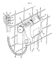
- FIG. 4 shows an overall view of the mixing device with a housing 80, which is fastened to the wall of a shower or bathroom and covers the mixing valve explained in FIG. 3.
- the mixer tap is located in the left part, with the setting wheels 113 already mentioned for manual actuation being shown in dash-dot lines.
- the housing 80 contains a removable cover 124 above the setting wheels 113, so that the setting wheels 113 are accessible for manual operation of the mixing valve if necessary.
- the battery 126 is interchangeably arranged in the left part of the housing.
- the housing 80 has a cover 125 and the battery can be replaced after opening the same.
- the one The plus or minus buttons 119, 120 set the setpoint of the mixing temperature.
- the actual value measured by the temperature sensor in the mixing chamber is shown on the display unit 117.
- the buttons 119, 120 are actuated, the setpoint is displayed on the same display unit 117 in the context of the invention.
- the changeover takes place automatically when buttons 119, 120 are pressed.
- the device automatically switches to the operating position.
- the mixing valves 105, 106 shown in FIG. 3 are brought into the position corresponding to the set temperature via the electric drive and the gear 110.
- actuation buttons 121 and 122 are provided for the mixed water.
- the mixed water outlet valve 109 is opened by means of the electric drive 111 via the gear 110 by means of the mixed water plus button 121. By pressing the plus 121 or minus button 112, the water outlet quantity is also regulated.
- the electronics 112 now continuously regulate the preset water temperature.
- the actual value measured with the temperature sensor 118 in the mixing chamber is compared with the entered target value and is automatically readjusted in the event of a deviation of in particular more than 1 degree Celsius. According to the invention, the readjustment is also ensured when the pressure and / or the temperature in the feed lines change. It is not necessary to emphasize that the preset temperature can be changed at any time by pressing the buttons 119, 120 even while showering.
- the mixing device also contains a safety device so that the mixed water does not exceed a maximum predetermined temperature.
- the electronics unit 112 is set to a maximum temperature in the factory, expediently about 38 degrees Celsius. If a higher temperature is desired, this electronic lock can nevertheless be unlocked according to the invention by pressing the temperature plus key 119 together with a protection key 123.
- the factory default value of in particular is automatically restored 38 degrees Celsius reset.
- the device is automatically switched off after the showering process has ended or if none of the buttons are pressed for a certain time, in particular between three to five minutes.
- This automatic switch-off essential to the invention effects: - The drain valve is closed - The mixing valves are moved to the "cold" position - The setpoint for the mixed water reaches the position of the basic value - The control and power section is switched off.
- the mixing device switches off automatically in the following cases: - Opening the cover 124 for manual actuation - Open the cover 125 to replace the battery 126 -
- the voltage, in particular the output voltage of the battery drops below a predetermined value.
- the display unit 117 also serves to display the drop in the voltage of the battery below a predetermined value, so that a user can then replace the battery.
- the device also contains the dispenser unit, which is expediently arranged in the other part under the housing 80.
- This dispenser or conveying unit is arranged in the other part of the housing 80, specifically in the right part of the same according to FIG. 4.
- the housing has a cover 130 which can be removed, in particular opened, in front of the drawing plane, behind which there is at least one container for a lotion, shower agent, shampoo or the like det. In the embodiment shown here, two such containers are provided so that two different means can be picked up and forwarded. There are still pumps to be explained below, the control being effected via the electronic unit by pressing the keys 131, 132.
- the outlet line of the housing of the mixer tap is led to the connection 134 for a shower hose 135.
- the shower hose contains five parts, namely a water hose 133, two hoses 137 for conveying and dispensing the funds contained in the above-mentioned containers, an electrical cable with a multiple plug and a coupling 138 for connection to the electronic unit and a movable outer casing 139.
- For the shower hose is provided with a device connection 134 and a connection 141 of the shower head 136. At the two hose ends there are multiple coupling pieces with union nuts 142, suitable seals being provided.
- a container 151 is shown, which is located behind the lid of the housing.
- the container 151 is arranged in guides 152, 153 which can be removed from the housing.
- the guides 152, 153 have corresponding grooves into which lateral bolts 154 of the container 151 are inserted.
- the container 151 can be lowered after a short lift and a small forward movement.
- This dispenser part also contains a pump 127, which is expediently designed as a peristaltic pump and is driven by an electric motor 129 via a gear 128.
- the hose 137 leading to the shower head is connected to the pump 127.
- the entire donor or conveyor unit in this embodiment contains at least two donor parts constructed in this way.
- the actuation takes place via the keys 131 and 132 designated with the letters A and B in FIG. 4, specifically via the electronic unit already described.
- the container 131 protrudes from above an intake port 155 through which the agent is sucked and ge via the hose 137 is promoted.
- FIGS. 6 and 7 show the multiple coupling in a radial or axial section.
- Surrounded by the outer sheath 139 is the shower hose 133 for the mixed water, the two hoses 137 for the agent and the electrical cable 138.
- the electrical cable contains a plurality of wires inside, which are connected to one another in an electrically conductive manner by means of suitable plug connectors 138a.
- At both hose ends there is a multiple coupling piece 140 which is to be connected to the respective connection by means of the union nut 142.
- the water-conducting shower hose 133 is tightly connected by means of a seal 143.
- FIGS. 8 and 9 schematically show the shower head 136, which contains a housing 144 and the keyboard 145.
- the following functions can be performed directly on the shower head 136 via this operating keyboard 145: - opening and closing of the mixed water outlet valve (regulating the water outlet quantity), - changing the water temperature, - Request one of means A or B.
- this keyboard 145 contains a total of six keys 119 to 122 and 131, 132, with which the same functions as with the corresponding keys of the wall-mounted device with the housing 80 can be triggered.
- a valve 146 with a nozzle 147 and a leakage protection 148 is arranged in the shower head. This valve is arranged in such a way that the agent, be it shower gel, lotion or the like, can flow through a normal outlet opening 149 of the water strainer 150. By means of de leak protection, it is ensured that the agent can only escape from the hose 137 if the pump of the dispenser unit is conveying agent under pressure.
- the water is turned off by pressing the button 122 marked with the minus sign, be it on the device or the housing 80 or the shower head 136.
- the corresponding agent is pumped through the associated hose 37 into the shower head 136 and passes there via the valve 146 and the nozzle 147 through the outlet opening 149 of the Water sieve 150.
- the water jet is set, when the A button 131 or B button 132 is actuated, be it on the device 80 or on the shower head 136 with the water jet running, the agent is mixed with the emerging water jet due to the special arrangement of the nozzle 147 .
Landscapes
- Public Health (AREA)
- Health & Medical Sciences (AREA)
- Engineering & Computer Science (AREA)
- Hydrology & Water Resources (AREA)
- Water Supply & Treatment (AREA)
- Life Sciences & Earth Sciences (AREA)
- Epidemiology (AREA)
- Molecular Biology (AREA)
- Physics & Mathematics (AREA)
- General Physics & Mathematics (AREA)
- Automation & Control Theory (AREA)
- Bathtubs, Showers, And Their Attachments (AREA)
- Domestic Plumbing Installations (AREA)
- Devices For Medical Bathing And Washing (AREA)
- Accessories For Mixers (AREA)
Priority Applications (8)
| Application Number | Priority Date | Filing Date | Title |
|---|---|---|---|
| IL88164A IL88164A0 (en) | 1987-10-28 | 1988-10-25 | Mixing device for showers or baths |
| FI884936A FI884936A7 (fi) | 1987-10-28 | 1988-10-26 | Blandaranordning. |
| PT8886288A PT88862A (pt) | 1987-10-28 | 1988-10-26 | Mischvorrichtung |
| CN 88108853 CN1035238A (zh) | 1987-10-28 | 1988-10-27 | 混合设备 |
| KR1019880014004A KR890006193A (ko) | 1987-10-28 | 1988-10-27 | 혼합장치 |
| NO88884793A NO884793L (no) | 1987-10-28 | 1988-10-27 | Blandebatteri. |
| JP63271926A JPH01158128A (ja) | 1987-10-28 | 1988-10-27 | 混合装置 |
| DK601388A DK601388A (da) | 1987-10-28 | 1988-10-28 | Blandingsindretning for varmt og koldt vand |
Applications Claiming Priority (2)
| Application Number | Priority Date | Filing Date | Title |
|---|---|---|---|
| DE19873736406 DE3736406A1 (de) | 1987-10-28 | 1987-10-28 | Mischvorrichtung, insbesondere fuer duschen oder baeder |
| DE3736406 | 1987-10-28 |
Publications (2)
| Publication Number | Publication Date |
|---|---|
| EP0313913A2 true EP0313913A2 (fr) | 1989-05-03 |
| EP0313913A3 EP0313913A3 (fr) | 1989-10-11 |
Family
ID=6339210
Family Applications (1)
| Application Number | Title | Priority Date | Filing Date |
|---|---|---|---|
| EP88116856A Withdrawn EP0313913A3 (fr) | 1987-10-28 | 1988-10-11 | Dispositif de mélange |
Country Status (6)
| Country | Link |
|---|---|
| US (1) | US4965894A (fr) |
| EP (1) | EP0313913A3 (fr) |
| KR (1) | KR890006193A (fr) |
| AU (1) | AU2444088A (fr) |
| DE (1) | DE3736406A1 (fr) |
| ZA (1) | ZA888116B (fr) |
Cited By (9)
| Publication number | Priority date | Publication date | Assignee | Title |
|---|---|---|---|---|
| EP0471244A1 (fr) * | 1990-08-17 | 1992-02-19 | Friedrich Grohe Aktiengesellschaft | Dispositif de contrôle et de commande d'une installation mélangeuse d'eau |
| EP0679770A3 (fr) * | 1994-04-30 | 1996-02-07 | Lepel Barbara | Méthode de manoeuvre d'un robinet d'eau et robinet d'eau fonctionnant selon cette méthode. |
| EP0711877A1 (fr) * | 1994-11-11 | 1996-05-15 | Nicola Borriello | Armature comprenant un élément de dosage pour la distribution de liquides de nettoyage et de desinfection et similaire |
| WO1996014477A1 (fr) * | 1994-11-08 | 1996-05-17 | American Standard Inc. | Robinet sanitaire debitant l'eau automatiquement |
| DE19638788A1 (de) * | 1996-09-21 | 1998-03-26 | Grohe Kg Hans | Sanitärarmatur |
| WO2008130349A1 (fr) | 2007-04-20 | 2008-10-30 | Kohler Co. | Interface utilisateur permettant de commander un appareil sanitaire de salle de bains |
| DE102016104477A1 (de) | 2016-03-11 | 2017-09-14 | Witzenmann Gmbh | Brauseschlauch |
| WO2020070154A1 (fr) | 2018-10-02 | 2020-04-09 | Gjosa Sa | Douche avec distributeur d'additif |
| WO2023222833A1 (fr) | 2022-05-19 | 2023-11-23 | Gjosa Sa | Dispositif de lavage et unité de conditionnement d'eau |
Families Citing this family (53)
| Publication number | Priority date | Publication date | Assignee | Title |
|---|---|---|---|---|
| DE3925590A1 (de) * | 1989-08-02 | 1991-02-07 | Preh Elektro Feinmechanik | Vorrichtung zum einstellen des badewassers einer badewanne |
| AU629044B2 (en) * | 1989-09-22 | 1992-09-24 | Michael Constantinos | A douche attachment for a toilet suite |
| WO1991003974A1 (fr) * | 1989-09-22 | 1991-04-04 | Michael Constantinos | Unite de douche pour w.-c. |
| DE3938533A1 (de) * | 1989-11-21 | 1991-05-23 | Rainer M Lutz | Wasserauslaufarmatur |
| USD340279S (en) | 1990-10-02 | 1993-10-12 | Knebel & Rottger Gmbh & Co. | Controller for bathroom fixtures |
| WO1993022714A1 (fr) * | 1992-05-07 | 1993-11-11 | Rottwest Pty. Ltd. | Dispositif de melange a vanne commandee electriquement |
| US5239712A (en) * | 1992-11-10 | 1993-08-31 | Kinder Gregory V | Shower for individual with hand dysfunction |
| DE4401637C2 (de) * | 1993-01-22 | 2001-08-23 | Hansgrohe Ag | Sanitäre Mischarmatur |
| US5794282A (en) * | 1997-02-28 | 1998-08-18 | Lucas; Carol A. | Temperature-indicating water diverter for water spout |
| DE19710800A1 (de) * | 1997-03-17 | 1998-10-01 | Ideal Standard | Elektrisch betriebene Armatur |
| US6264121B1 (en) * | 1997-05-13 | 2001-07-24 | Mcclary Nobia | Adjustable hand-held shower apparatus |
| IT247677Y1 (it) * | 1999-11-18 | 2002-09-09 | Matteucci Valerio | Apparecchio manuale per l'idropulitura di un vaso igenico. |
| DE20008256U1 (de) | 2000-05-08 | 2000-08-17 | Hansgrohe AG, 77761 Schiltach | Duscheinrichtung |
| EP1323872A1 (fr) * | 2001-12-28 | 2003-07-02 | Ewig Industries Co., LTD. | Module de commande multifonctionnelle de l'eau |
| US6676024B1 (en) * | 2002-09-05 | 2004-01-13 | Masco Corporation | Thermostatic valve with electronic control |
| WO2005054592A1 (fr) * | 2003-12-04 | 2005-06-16 | Meng Chow | Systeme de generation de mousse |
| US7690395B2 (en) | 2004-01-12 | 2010-04-06 | Masco Corporation Of Indiana | Multi-mode hands free automatic faucet |
| RU2313712C2 (ru) * | 2005-03-10 | 2007-12-27 | Петр Тихонович Харитонов | Смеситель жидкостей с бесконтактным управлением |
| US7458520B2 (en) | 2005-04-19 | 2008-12-02 | Masco Corporation Of Indiana | Electronic proportioning valve |
| US7475827B2 (en) | 2005-04-19 | 2009-01-13 | Masco Corporation Of Indiana | Fluid mixer |
| US7448553B2 (en) | 2005-04-19 | 2008-11-11 | Masco Corporation Of Indiana | Fluid mixer |
| US7584898B2 (en) | 2005-07-01 | 2009-09-08 | Masco Corporation Of Indiana | Manual override for electronic proportioning valve |
| US8438672B2 (en) | 2005-11-11 | 2013-05-14 | Masco Corporation Of Indiana | Integrated electronic shower system |
| US7867172B1 (en) | 2006-11-09 | 2011-01-11 | Dingane Baruti | Combination toothbrush and peak flow meter system |
| US8118240B2 (en) | 2006-04-20 | 2012-02-21 | Masco Corporation Of Indiana | Pull-out wand |
| US8089473B2 (en) | 2006-04-20 | 2012-01-03 | Masco Corporation Of Indiana | Touch sensor |
| US9243756B2 (en) | 2006-04-20 | 2016-01-26 | Delta Faucet Company | Capacitive user interface for a faucet and method of forming |
| US8365767B2 (en) | 2006-04-20 | 2013-02-05 | Masco Corporation Of Indiana | User interface for a faucet |
| US8162236B2 (en) | 2006-04-20 | 2012-04-24 | Masco Corporation Of Indiana | Electronic user interface for electronic mixing of water for residential faucets |
| US20080006707A1 (en) * | 2006-07-06 | 2008-01-10 | Fabrizio Nobili | Showerhead with simplified actuator |
| US9243392B2 (en) | 2006-12-19 | 2016-01-26 | Delta Faucet Company | Resistive coupling for an automatic faucet |
| CA2676976C (fr) | 2007-01-31 | 2015-10-06 | Masco Corporation Of Indiana | Appareil et procede de detection capacitive pour des robinets |
| US7806141B2 (en) | 2007-01-31 | 2010-10-05 | Masco Corporation Of Indiana | Mixing valve including a molded waterway assembly |
| WO2008118402A1 (fr) | 2007-03-28 | 2008-10-02 | Masco Corporation Of Indiana | Capteur tactile capacitif amélioré |
| US20090045268A1 (en) * | 2007-08-17 | 2009-02-19 | Selander Raymond K | Automatic Metered Personal Dispensing System |
| MX2010006473A (es) | 2007-12-11 | 2010-09-22 | Masco Corp | Disposicion de acoplamiento capacitivo para un grifo. |
| US9050612B2 (en) * | 2009-03-19 | 2015-06-09 | Delta Faucet Company | Shower device with independently operating valves |
| DE102009017497A1 (de) * | 2009-04-16 | 2010-10-21 | Airbus Deutschland Gmbh | Wasserversorgungsmodul |
| US9481000B2 (en) * | 2010-03-18 | 2016-11-01 | Graco Minnesota Inc. | Adjusting pump flow at tool |
| US8561626B2 (en) | 2010-04-20 | 2013-10-22 | Masco Corporation Of Indiana | Capacitive sensing system and method for operating a faucet |
| US8776817B2 (en) | 2010-04-20 | 2014-07-15 | Masco Corporation Of Indiana | Electronic faucet with a capacitive sensing system and a method therefor |
| GB201010097D0 (en) * | 2010-06-16 | 2010-07-21 | Gilbert Patrick C | Flow rate balancing devices |
| EP2823107A4 (fr) | 2012-03-07 | 2016-06-15 | Moen Inc | Raccord d'équipement de plomberie électronique |
| MX347296B (es) | 2012-04-20 | 2017-04-21 | Masco Corp | Grifo que incluye un pico extensible con sensor capacitivo. |
| ES2443083B1 (es) * | 2012-07-17 | 2014-09-10 | Bnstar Innovations, S. L. | Conjunto empotrable de conexión hidráulica |
| WO2014018564A1 (fr) | 2012-07-23 | 2014-01-30 | Zieger Claus Dieter | Procédés et système de répartition de proportions multiples |
| CA2882717C (fr) | 2012-08-23 | 2020-12-15 | Elkay Manufacturing Company | Systeme de distribution d'eau froide |
| WO2017042724A1 (fr) * | 2015-09-10 | 2017-03-16 | Rachapudi Vamsi Krishna | Système et procédé pour optimiser l'utilisation d'eau et d'autres ressources dans des applications résidentielles et commerciales |
| US20180271336A1 (en) * | 2017-03-24 | 2018-09-27 | Garfield Ron Mingo | Multi-function automatic liquid soap dispenser |
| JP6452082B1 (ja) * | 2018-02-26 | 2019-01-16 | Toto株式会社 | 水栓装置 |
| US10761546B2 (en) * | 2018-10-30 | 2020-09-01 | Lunal Corp. | Anti-scalding water outlet device |
| JP2023115712A (ja) * | 2022-02-08 | 2023-08-21 | Toto株式会社 | 水まわり装置 |
| CN119173669A (zh) * | 2022-05-11 | 2024-12-20 | 富俊水创新有限责任公司 | 包含通过喷头软管进行有线通信的喷头的电子管道系统 |
Family Cites Families (13)
| Publication number | Priority date | Publication date | Assignee | Title |
|---|---|---|---|---|
| US3322350A (en) * | 1964-12-14 | 1967-05-30 | Heinicke Instr Company | Mobile washing apparatus for vehicles or aircraft having chemical mixing means therein |
| DE2606143A1 (de) * | 1976-02-17 | 1977-08-18 | Jun Herbert Heuer | Zwangszumischer |
| US4218013A (en) * | 1978-08-11 | 1980-08-19 | Davison Charles A | Shower head fluid dispenser |
| DE2918575C2 (de) * | 1979-05-09 | 1983-03-24 | R. und D. Rotter GmbH med.chem. Apparate- und Anlagenbau, 6086 Riedstadt | Gerät zum Dosieren und Zumischen von Desinfektionsmittel in eine Wasserzapfstelle |
| DE2925234A1 (de) * | 1979-06-22 | 1981-05-27 | H.D. Eichelberg & Co Gmbh, 5860 Iserlohn | Regelung fuer sanitaere mischbatterien |
| US4621770A (en) * | 1981-12-14 | 1986-11-11 | Sayen Michael D | Plant watering/misting device |
| CH658485A5 (de) * | 1982-11-02 | 1986-11-14 | Karrer Weber & Cie Ag | Sanitaerinstallation mit wenigstens einer steuerarmatur und separater wasserausgabevorrichtung. |
| US4742456A (en) * | 1983-03-18 | 1988-05-03 | American Standard Inc. | Sound responsive tube control circuit |
| US4563780A (en) * | 1983-06-29 | 1986-01-14 | Pollack Simcha Z | Automated bathroom |
| NO152880C (no) * | 1983-08-30 | 1985-12-04 | Lyng Ind As | Temperaturpaavirkbar, elektronisk styrt blandeventil for blanding av to vaesker. |
| US4606085A (en) * | 1985-03-27 | 1986-08-19 | Davies Joseph R | Hand washing device |
| DE3537678A1 (de) * | 1985-10-23 | 1987-04-23 | Peter Wilfred Auge | Beruehrungslos betaetigbare absperrarmatur fuer fluessigkeiten |
| US4839039B2 (en) * | 1986-02-28 | 1998-12-29 | Recurrent Solutions Ltd | Automatic flow-control device |
-
1987
- 1987-10-28 DE DE19873736406 patent/DE3736406A1/de not_active Ceased
-
1988
- 1988-10-11 EP EP88116856A patent/EP0313913A3/fr not_active Withdrawn
- 1988-10-27 AU AU24440/88A patent/AU2444088A/en not_active Abandoned
- 1988-10-27 KR KR1019880014004A patent/KR890006193A/ko not_active Abandoned
- 1988-10-28 US US07/263,902 patent/US4965894A/en not_active Expired - Fee Related
- 1988-10-28 ZA ZA888116A patent/ZA888116B/xx unknown
Cited By (15)
| Publication number | Priority date | Publication date | Assignee | Title |
|---|---|---|---|---|
| US5174495A (en) * | 1990-08-17 | 1992-12-29 | Friedrich Grohe Armaturenfabrik Gmbh & Co. | Adjusting and servicing a computer-controlled mixing valve |
| EP0471244A1 (fr) * | 1990-08-17 | 1992-02-19 | Friedrich Grohe Aktiengesellschaft | Dispositif de contrôle et de commande d'une installation mélangeuse d'eau |
| EP0679770A3 (fr) * | 1994-04-30 | 1996-02-07 | Lepel Barbara | Méthode de manoeuvre d'un robinet d'eau et robinet d'eau fonctionnant selon cette méthode. |
| US5855356A (en) * | 1994-11-08 | 1999-01-05 | American Standard, Inc. | Sanitary tap for automatic water delivery |
| WO1996014477A1 (fr) * | 1994-11-08 | 1996-05-17 | American Standard Inc. | Robinet sanitaire debitant l'eau automatiquement |
| EP0711877A1 (fr) * | 1994-11-11 | 1996-05-15 | Nicola Borriello | Armature comprenant un élément de dosage pour la distribution de liquides de nettoyage et de desinfection et similaire |
| DE19638788A1 (de) * | 1996-09-21 | 1998-03-26 | Grohe Kg Hans | Sanitärarmatur |
| WO2008130349A1 (fr) | 2007-04-20 | 2008-10-30 | Kohler Co. | Interface utilisateur permettant de commander un appareil sanitaire de salle de bains |
| CN101689047B (zh) * | 2007-04-20 | 2012-05-09 | 科勒公司 | 用于控制浴室卫生器具的用户界面 |
| US9128495B2 (en) | 2007-04-20 | 2015-09-08 | Kohler Co. | User interface for controlling a bathroom plumbing fixture |
| US9910578B2 (en) | 2007-04-20 | 2018-03-06 | Kohler Co. | User interface for controlling a bathroom plumbing fixture with outlet and flow pattern selection screens |
| DE102016104477A1 (de) | 2016-03-11 | 2017-09-14 | Witzenmann Gmbh | Brauseschlauch |
| WO2020070154A1 (fr) | 2018-10-02 | 2020-04-09 | Gjosa Sa | Douche avec distributeur d'additif |
| CN112752886A (zh) * | 2018-10-02 | 2021-05-04 | 戈约萨股份公司 | 具有添加剂分配器的淋浴器 |
| WO2023222833A1 (fr) | 2022-05-19 | 2023-11-23 | Gjosa Sa | Dispositif de lavage et unité de conditionnement d'eau |
Also Published As
| Publication number | Publication date |
|---|---|
| US4965894A (en) | 1990-10-30 |
| ZA888116B (en) | 1989-07-26 |
| DE3736406A1 (de) | 1989-05-24 |
| AU2444088A (en) | 1989-05-04 |
| KR890006193A (ko) | 1989-06-12 |
| EP0313913A3 (fr) | 1989-10-11 |
Similar Documents
| Publication | Publication Date | Title |
|---|---|---|
| EP0313913A2 (fr) | Dispositif de mélange | |
| DE60006928T2 (de) | Vorrichtung zum Abgeben und Mischen von Wasser | |
| DE3338064C2 (fr) | ||
| EP0292860A2 (fr) | Mélangeur thermostatique électronique | |
| DE19623104C2 (de) | Als Einhebelmischer ausgebildete Sanitärarmatur | |
| EP0061561B1 (fr) | Mélangeur mural | |
| DE60008853T2 (de) | Vorrichtung zur automatischen Wasserabgabe | |
| EP1853769A1 (fr) | Systeme de douche | |
| EP2406432A1 (fr) | Robinetterie comportant une cartouche sous la céramique sanitaire | |
| DE69721248T2 (de) | Durchflussregelungsvorrichtung mit einem mittels unerschöpflicher energie gesteuertem ventil | |
| EP3173538B1 (fr) | Dispositif de raccordement | |
| DE3022706C2 (de) | Einloch-Mischarmatur | |
| DE3025603A1 (de) | Elektronisch gesteuerte waschtischarmatur | |
| EP3843598A1 (fr) | Dispositif de douchette transportable | |
| EP2516902A1 (fr) | Ensemble sanitaire de distribution | |
| EP1520629B1 (fr) | Installation de douche | |
| DE3537678A1 (de) | Beruehrungslos betaetigbare absperrarmatur fuer fluessigkeiten | |
| DE2945834A1 (de) | Ventil fuer fluide, insbesondere in einem spueler, einer mischbatterie oder einem hahn o.dgl. armaturen fuer installationszwecke | |
| DE3841911C2 (de) | Sanitärarmatur | |
| DE19649937C2 (de) | Badewannenarmatur mit integrierter Schmutzwasserrücklaufsicherung | |
| EP0139909B1 (fr) | Elément de construction sanitaire pour régler la distribution ainsi que l'évacuation de l'eau dans ou hors d'une baignoire ou similaire | |
| DE10057591C1 (de) | Mischbatterie | |
| EP0855635B1 (fr) | Robinetterie sanitaire | |
| JPH01158128A (ja) | 混合装置 | |
| DE102007011178A1 (de) | Elektrische Steuereinrichtung für eine Sanitärarmatur sowie Santiärarmatur mit einer solchen Steuereinrichtung |
Legal Events
| Date | Code | Title | Description |
|---|---|---|---|
| PUAI | Public reference made under article 153(3) epc to a published international application that has entered the european phase |
Free format text: ORIGINAL CODE: 0009012 |
|
| AK | Designated contracting states |
Kind code of ref document: A2 Designated state(s): AT BE CH DE ES FR GB GR IT LI NL SE |
|
| PUAL | Search report despatched |
Free format text: ORIGINAL CODE: 0009013 |
|
| AK | Designated contracting states |
Kind code of ref document: A3 Designated state(s): AT BE CH DE ES FR GB GR IT LI NL SE |
|
| 17P | Request for examination filed |
Effective date: 19891031 |
|
| DIN1 | Information on inventor provided before grant (deleted) | ||
| RAP1 | Party data changed (applicant data changed or rights of an application transferred) |
Owner name: DUSCHOLUX GMBH Owner name: ALTURA LEIDEN HOLDING B.V. |
|
| 17Q | First examination report despatched |
Effective date: 19911107 |
|
| STAA | Information on the status of an ep patent application or granted ep patent |
Free format text: STATUS: THE APPLICATION IS DEEMED TO BE WITHDRAWN |
|
| 18D | Application deemed to be withdrawn |
Effective date: 19920318 |