EP0314018B1 - Verfahren und Vorrichtung für multiplexierte Vektorquantifizierung - Google Patents
Verfahren und Vorrichtung für multiplexierte Vektorquantifizierung Download PDFInfo
- Publication number
- EP0314018B1 EP0314018B1 EP88117612A EP88117612A EP0314018B1 EP 0314018 B1 EP0314018 B1 EP 0314018B1 EP 88117612 A EP88117612 A EP 88117612A EP 88117612 A EP88117612 A EP 88117612A EP 0314018 B1 EP0314018 B1 EP 0314018B1
- Authority
- EP
- European Patent Office
- Prior art keywords
- vector
- distortion
- candidate vectors
- calculating
- candidate
- Prior art date
- Legal status (The legal status is an assumption and is not a legal conclusion. Google has not performed a legal analysis and makes no representation as to the accuracy of the status listed.)
- Expired - Lifetime
Links
Images


Classifications
-
- G—PHYSICS
- G06—COMPUTING OR CALCULATING; COUNTING
- G06T—IMAGE DATA PROCESSING OR GENERATION, IN GENERAL
- G06T9/00—Image coding
- G06T9/008—Vector quantisation
-
- H—ELECTRICITY
- H03—ELECTRONIC CIRCUITRY
- H03M—CODING; DECODING; CODE CONVERSION IN GENERAL
- H03M7/00—Conversion of a code where information is represented by a given sequence or number of digits to a code where the same, similar or subset of information is represented by a different sequence or number of digits
- H03M7/30—Compression; Expansion; Suppression of unnecessary data, e.g. redundancy reduction
- H03M7/3082—Vector coding
-
- H—ELECTRICITY
- H04—ELECTRIC COMMUNICATION TECHNIQUE
- H04N—PICTORIAL COMMUNICATION, e.g. TELEVISION
- H04N19/00—Methods or arrangements for coding, decoding, compressing or decompressing digital video signals
- H04N19/90—Methods or arrangements for coding, decoding, compressing or decompressing digital video signals using coding techniques not provided for in groups H04N19/10-H04N19/85, e.g. fractals
- H04N19/94—Vector quantisation
Definitions
- the present invention relates to a method for coding a signal sequence of speech or image with a small amount of information and, more particularly, to a multiplexed vector quantization method and apparatus therefor which are robust against transmission channel errors.
- a vector quantization method is known as an effective method for coding a signal sequence with a small amount of information. According to this method, discrete values of successive signal samples to be coded are grouped for each predetermined number and defined as a vector for each group, each vector is checked with a codebook containing reconstruction vectors and the index of a reconstruction vector that will minimize a quantization distortion is used as an output code.
- Fig. 1 shows the general arrangement for the conventional vector quantization method.
- Reference numerals 21 and 23 indicate codebooks, 22 an encoder and 24 a decoder. Symbols used herein have the following meanings:
- This quantization method essentially has the defect of reconstructing a vector entirely different from the input vector when there are channel errors, because the index and the value of the reconstruction vector bear no relationship in terms of distance.
- the code error rate can significantly be lowered by, for example, using additional redundant bits the amount of which accounts for 50% of the amount of information bits involved.
- this method always requires the same amount of redundant bits even for an error-free channel. That is, where the total amount of information to be transmitted is fixed, the amount of information bits available is only 2/3 of the total amount of information to be sent even if the channel is free from errors, and the quantization distortion will naturally increase.
- the document ICASSP'86 PROCEEDINGS, 7th-11th April 1986, pages 3095-397 discloses a vector quantizer and a vector quantizing method which differs from the principle explained above in that quantization is performed in plural stages, an example of two stages being disclosed in the said document.
- each stage uses its own codebook.
- the first stage quantizes an input vector and supplies a quantized output corresponding to an index in a first codebook associated with it.
- the difference vector between the input vector and the output of the first stage is then further quantized by a second stage providing a second quantized output corresponding to an index in the second codebook associated with the second stage.
- the reproduction vector is the sum of the two quantized outputs.
- the two indexes of the two stages are used for transmission or storage.
- the problems involved in this multi stage quantization method are substantially the same as those explained above with respect to Fig. 1.
- An object of the present invention is to provide a vector quantization method and apparatus therefor in which the decoded signal is not seriously distorted even if a code error occurs in the coding of a signal sequence of speech or image through compression of its information and in which the amount of computation and/or the storage capacity of a memory necessary for the coding are both small.
- This object is achieved with a multiplexed vector quantizer and a multiplexed vector quantization method, respectively, as claimed.
- a plurality of channels of codebooks are provided and, for each input vector, a set of candidate vectors which yield the smallest distortion between the input vector and the averaged vector of these candicate vectors are selected each from a different one of the codebooks in the respective channels, and then index codes of the respective candidate vectors are multiplexed and output as a transmitting code.
- Fig. 2 illustrates in block form the general arrangement of a transmission system which employs the vector quantizer according to an embodiment of the present invention.
- Reference numerals 11, 12 and 15, 16 indicate codebooks, 13 an encoder, 14 a multiplexer, 17 a decoder and 18 a vector combiner.
- This embodiment shows the case where codebooks of two channels are provided; namely, the codebooks 11 and 15 are X-channel and codebooks 12 and 16 Y-channel. Symbols used in the following description are defined as follows:
- the encoder 13 upon application of one input vector u the encoder 13 refers to the two codebooks 11 and 12 and performs, for each of them, a vector quantization using the half of the amount of information (k ⁇ r bits) assigned to the quantized transmitting code b. That is, the number of bits of each of quantized index codes b x and b y of the respective channels is represented by k ⁇ r/2.
- the decoder 17 refers to the codebooks 15 and 16 on the basis of the index codes b x and b y of the respective channels contained in the transmitted code b and obtains candidate vectors x and y of the respective channels.
- the vector combiner 18 obtains an arithmetic mean of the output vectors x and y , providing it as an ultimate reconstruction vector.
- Fig. 3 illustrates a specific operative example of the arrangement of the vector quantizer 100 of the present invention.
- Each field of the X-channel codebook 11 contains a candidate vector x j and its vector index j (i.e. a quantized index code b x ).
- each field of the Y-channel codebook 12 also contains a candidate vector y m and its vector index m (i.e. a quantized index code b y ).
- the numbers of candidate vectors x j and y m of the codebooks 11 and 12 of the respective channels are each 2 kr/2 as mentioned above in respect of Fig. 2.
- the vector indices j and m are each composed of kr/2 bits.
- the vector indices j and m are each represented by four bits, for the sake of convenience.
- the encoder 13 can be separated into an average candidate vector computing section 131, a squared distance computing section 132 and a minimum distance determining section 133.
- the squared distance computing section 132 computes, for each of all combinations (j,m), a distortion d j,m between the input vector u and the above-mentioned average vector v j,m which is represented by a squared distance.
- the minimum distance determining section 133 sequentially receives each combination of the candidate vectors x j and y m of the both channels and the corresponding distortion d j,m between the input vector u and the average vector v j,m and determines a combination of candidate vectors x j , y m which minimizes the distortion d j,m . Based on the thus determined combination of candidate vectors x j and y m , the minimum distance determining section 133 refers to the codebooks 11 and 12 and outputs their vector indices j and m as quantized index codes b x and b y .
- the vector indices j and m (i.e. quantized index codes b x and b y ) of the respective channels are multiplexed together by the multiplexer 14, providing the original vector quantized code b for the input vector u .
- the candidate vectors x j and y m are selected from the two codebooks X and Y for the input vector u and the vector indices j and m are determined which minimize the distortion d between the average ( x j + y m )/2 of the candidate vectors and the input vector u ; so that the probability that the distance between the selected candidate vectors x j and y m is short is very high.
- the candidate vectors x j and y m are read out of the X-channel codebook 11 and the Y-channel codebook 12, respectively, a calculation u(i) - x(i,j) - y(i,m) is performed by an adder 31 using the corresponding i-th elements u(i), x(i,j) and y(i,m) of the input vector and the candidate vectors, and the added output is squared and accumulated by a square accumulator 32.
- the number of combinations of the candidate vectors x j and y m is N2.
- 3kN2 computation are needed for obtaining the distortion d j,m for each of the combinations and for determining the vector index pair (j,m) which provides the smallest distortion d j,m . This amount of computation is rather larger than that needed in the conventional vector quantizer shown in Fig.
- Eq. (4) can be expanded to the following equation (5): where
- the first term of Eq. (5) has nothing to do with the selected candidate vector index pair (j, m). Accordingly, there is no need of calculating u2(i) for determining the vector index pair (j, m) which provides the smallest distortion d j,m . Then it is sufficient to determine the vector index pair of (j, m) which yields the smallest distortion d′ j,m which is defined by the following equation (7), instead of Eq. (5).
- the second term F(j,m) is unrelated to the input vector u as defined by Eq.
- Fig. 5 illustrates an example in which the averaged candidate vector computing section 131, the squared distance computing section 132 and the codebooks 11 and 12 in the embodiment of Fig. 3 are arranged on the basis of Eq. (7).
- a table memory 33 is provided which has stored therein the values of F(j, m) calculated for all the combinations of vector indices (j, m) by Eq. (6) as described above.
- the first term of Eq. (7) is the sum of the inner product of the vectors u and x j and the inner product of the vectors u and y m , which are calculated by inner product calculators 34 and 35, respectively.
- the inner product calculated results are each provided as a scalar value to an adder 36, wherein they are added to the corresponding value of F(j, m) read out of the table memory 33.
- the output of the adder 36 is the result of calculation of the distortion d′ j,m by Eq. (7).
- This embodiment involves 2kN inner product calculations by the inner products calculators 34 and 35 and 2N2 scalar additions/subtractions by the adder 36 and requires a storage capacity 2kN for the codebooks 11 and 12 and a storage capacity N2 for the table memory 33.
- w(i) indicates an i-th element of a weighting vector w , which changes each time the i-th element u(i) of the input vector u changes but remains unchanged together with the i-th element u(i) during the calculation of the minimum value of the distortion d.
- w(i) is fixed regardless of u(i)
- the case renders to that of utilizing the squared distance expressed by Eq. (4).
- Fig. 6 illustrates an arrangement for executing the above-described computation in the embodiment of Fig. 3.
- the table memory 33 has prestored kN2 values of F(i,j,m) given by Eq. (10).
- the weighting vector w is input into the vector quantizer, together with the input vector u , and the corresponding i-th elements of these vectors are multiplied by a multiplier 37 as expressed by Eq. (12).
- the calculated outputs from the inner product calculators 34, 35 and 38 are applied to the adder 36, wherein the scalar operation of Eq. (15) takes place, obtaining the value d* j,m corresponding to the distortion in the case where the input vector u is encoded into j,m.
- Table II shows the amount of computation and the storage capacity needed in the embodiment of Fig. 6.
- Table II there are also shown, for the purpose of comparison, the amount of computation and the storage capacity which are required in the cases where the weight w is included in Eq. (1) corresponding to Fig. 1 and Eq. (4) corresponding to Fig. 4 as is the case with Eq. (8), but no description will be given of them, because they can easily be obtained in the same manner as described above.
- the methods (2) and (3) are each larger in either the amount of computation or storage capacity than in the method (1), but by combining the methods (2) and (3) both the amount of computation and the storage capacity can be reduced as compared with those in the method (1).
- This can be achieved by partly prestoring, in the form of a table, the values of F(i,j,m) in Eq. (9). Letting the ratio of the number of values to be prestored to the total number of values of F(i,j,m) be represented by ⁇ (where 0 ⁇ ⁇ ⁇ 1), the amount of computation and the storage capacity required are 2N2 + k + 2kN + (3 - 2 ⁇ ) and 2kN + ⁇ kN2, respectively. A suitable selection of the above-mentioned ratio ⁇ will permit a trade-off between the amount of computation and the storage capacity so as to meet given requirements of design.
- the present invention can also be applied easily to the case where the distance measure includes a free parameter ⁇ which is multiplied with the candidate vectors in the codebooks as shown in Eq. (16).
- a distortion measure expressed by the following equation has often been utilized in the quantization of a residual signal of speech in the time domain. The calculation of this distortion d l is performed using one codebook Z. Adopting this distortion measure, the distortion d j,m in the vector quantization method of the present invention can be expressed as follows: where h(i,g) is an element at an i-th row and a g-th column of a matrix H for obtaining a convolution product and ⁇ is a parameter which is determined so that the distortion d j,m becomes minimum.
- d j,m ⁇
- ⁇ is a parameter from 0 to 1. If ⁇ is set to 1, then the above distortion will be equivalent to the distortion by Eq. (3), and if ⁇ is selected smaller, then the redundancy of each codebook will increase, permitting the reduction of the distortion if one of the two channels is free from errors. That is, the robustness against transmission channel errors is increased.
- the final output reconstruction vector is produced at the receiving side as a simple arithmetic average, since it is assumed that the same amount of information is distributed to a plurality of channels; however, when the amount of information differs with the channels, the final output reconstruction vector is produced as a weighted average.
- Fig. 7 shows the case of locally minimizing the distortion by alternate renewal of the two codebooks, but the procedure shown can also be applied to the preparation of more than two codebooks.
- step S0 a number of vectors are prepared which are each composed of k consecutive samples extracted from a training sample sequence at an arbitrary position, and these vectors are separated into two groups, each consisting of initial candidate vectors of the same number, by which initial codebooks X and Y are prepared.
- a group of vectors obtained by ordinary vector quantization training through use of training samples may be used as the codebook X and a group of vectors obtained using a sequence of its errors may be used as the codebook Y.
- step S1 training vectors sufficiently greater in number than the candidate vectors are used as input vectors u and the distortion d, for example, by Eq. (3) between each input vector u and every candidate vector pair x j , y m is calculated, thereby determining the candidate vector pair x j , y m which provides the smallest distortion d.
- each input vector u is quantized by the quantization method of the present invention and the candidate vector pair x j , y m is determined to which each input vector u corresponds.
- step S2 the sum total D of the minimum distortions d calculated in step S1 for all input vectors is calculated, and if the sum total D or its improvement ratio is below a threshold value, then it is judged that the codebooks X and Y are composed of candidate vectors desired to obtain, and the training is stopped. If not so, the training sequence proceeds to step S3, in which the contents y m of the codebook Y are renewed, with the contents x j held unchanged.
- each of the candidate vectors y m is regarded as a variable vector; an equation expressing the sum of distortions of all input vectors u corresponding to those vector pairs which contain the same variable vector y m , is partially differentiated by the variable vector y m and set to zero; and a vector value y m obtained by solving the differentiated equation for the variable vector y m is used as a new candidate vector y m .
- step S3 ⁇ 2 Letting all of P (where P is variable) input vectors containing the candidate vector y m in their corresponding vector pairs be represented by u m1 , u m2 , ..., u mP and the corresponding vector pairs by ( x f1 , y m ), ( x f2 , y m ), ( x f3 , y m ), ..., ( x fP , y m ), the vector value ⁇ m is given as their centroid by the following equation:
- step S3 ⁇ 2 in which the fixed codebook X and the renewed codebook Y are used to determine the correspondence of each input vector u to the candidate vector in the codebook Y, with the correspondence of each input vector u to the candidate vector in the codebook X fixed in the state in step S1.
- step S3 ⁇ 3 the codebook Y is renewed again in the same manner as in step S3 ⁇ 1.
- step S4 a candidate vector pair ( x j , y m ) corresponding to each input vector u is determined using the codebook X and the renewed codebook Y. Step S4 is equivalent to step S1.
- step S5 the contents of the codebook X are renewed, with the contents of the codebook Y fixed. That is, in step S5 ⁇ 1 the candidate vector x j is regarded as a variable vector for the candidate vector pairs ( x j y m ) corresponding to the respective input vectors u , determined in step S4; an equation expressing the sum of distortions of all input vectors u corresponding to those vector pairs which contain the same variable vector x j , is partially differentiated by the variable vector x j and set to zero; and a value x ⁇ j obtained by solving the differentiated equation for the variable vector x j is used as a new candidate vector x j .
- step S5 ⁇ 2 the renewed codebook X and the fixed codebook Y are used to determine the correspondence of each input vector u to the candidate vector in the codebook X, with the correspondence of each input vector u to the candidate vector in the codebook Y fixed in the state in step S4. Then, in step S5 ⁇ 3 the codebook X is renewed again in the same manner as in step S5 ⁇ 1.
- step S1 The training sequence goes back to step S1, thereafter performing the same iterative operations as mentioned above in step S2 to S5.
- the renewal of the codebooks X and Y is continued until the sum total D of the distortions or its improvement ratio becomes smaller than the threshold value.
- steps S3 ⁇ 2, S3 ⁇ 3 and S5 ⁇ 2, S5 ⁇ 3 may also be omitted. Further, these steps may also be repeated alternately.
- Fig. 8 shows, in terms of SNR, how the distortion is reduced by the codebook training.
- symbols ⁇ , ⁇ , ⁇ , ⁇ and ⁇ correspond to the steps S1, S3 ⁇ 1, S3 ⁇ 2, S5 ⁇ 1 and S5 ⁇ 2 in the flowchart of Fig. 7, respectively.
- the distortion always decreases, no matter how many times the pair of steps S3 ⁇ 1 and S3 ⁇ 2 and the pair of steps S5 ⁇ 1 and S5 ⁇ 2 may be iterated.
- Figs. 9A and 9B show the performance comparison between the conventional single-channel quantizer depicted in Fig. 1 (Fig. 9A) and the two-channel quantizer by the present invention (Fig. 9B) in terms of the region of the damage by a transmitted code error, the error bit being encircled. Since the provision of plural channels of codebooks and plural transmitting codes for each input vector divides the unit in which the codes are transmitted, the probability of occurrence of code errors in all the channels is lower than the error rate of ordinary transmitted codes which are not divided in their transmission unit. In other words, the region of the damage by a code error of one bit in the case of the two channels is one-half that in the case of one channel, as indicated by hatching in Figs. 9A and 9B.
- the Laplacian distribution simulates a linear prediction residual signal of a speech signal.
- the curve (a) indicates the two-channel quantization and the curves (b) to (e) the conventional single-channel quantization.
- the abscissa represents a bit error rate and the ordinate SNR. It appears from Fig. 10 that the two-channel quantizer has about the same performance as the single-channel quantizer of the same dimension in the case of no code error but is superior to the latter when there are code errors.
- Fig. 11 shows the performance of the two-channel quantizer according to the present invention in comparison with conventional quantizers using vector quantized codes and error correcting codes, with the total amount of information fixed.
- the correcting codes used are seven kinds of BCH codes capable of a multiple error correction.
- the numerals in the parentheses represent the total number of information bits, the number of source bits and the number of error correctable bits.
- Fig. 12 an example of the two-channel vector quantization of the present invention is shown as being applied to the transform coding of speech with weighted vector quantization which is one of effective techniques for medium band speech coding.
- An input digital speech signal S is applied to a linear prediction analyzer 41, from which a set of linear prediction parameters ⁇ i ⁇ are provided as filter coefficients to an inverse filter 42, providing a linear prediction residual signal R.
- the residual signal R is cosine-transformed by a cosine transformer 43 and its DCT (Discrete Cosine Transformation) coefficients are rearranged on the frequency axis and split into a plurality of sub-vectors.
- DCT Discrete Cosine Transformation
- a vector u thus obtained is provided to a two-channel weighted vector quantizer 100 according to the present invention, in which the input vector u is subjected to vector quantization by being added with the weight of a spectral envelope, and from which the quantized code is transmitted as waveform information B.
- side information A which consists of a pitch period ⁇ t, the linear prediction parameters ⁇ i ⁇ and signal power P is also encoded and transmitted.
- a decoder 200 at the receiving side refers to the codebooks 15 and 16 and reconstructs the candidate vector pair x j , y m from the received waveform information B and then outputs their averaged vector as a reconstruction vector from the decoder 17 and 18.
- the reconstruction vector is applied to a cosine inverse transformer 14, by which a residual signal R′ is decoded.
- the received parameter information A is decoded by a parameter decoder 45, and the linear prediction parameters ⁇ i ⁇ are applied as filter coefficients to a synthesis filter 46.
- the residual signal R′ is applied to the synthesis filter 46, synthesizing speech.
- the codebooks 11, 12 (and 15, 16) for the two-channel quantization are prepared by training first from a Gaussian random number sequence using a distortion measure weighted with a long-term averaged spectrum.
- the vector produced at this time is substantially zero in the power of a component corresponding to the high-frequency band on the frequency axis, resulting in decoded speech lacking the high-frequency component.
- the candidate vector is replaced with a vector which is the smallest in the weighted distance among the Gaussian random numbers of the training sequence.
- Fig. 13 shows the SNR performance of the two-channel vector quantization for transmission channel errors in Fig. 12, in comparison with the SNR performance of the conventional single-channel vector quantization depicted in Fig. 1.
- the input speech S is male and female speech, which are repeatedly used in different code error patterns, and the SNR plots represent values averaged over about 90 seconds of speech.
- the curves (b) and (c), except (a) indicate the case where the ordinary single-channel vector quantization was used for waveform quantization.
- the side information B in all the cases of the curves (a), (b) and (c) and the waveform information A in the case (c) an error correction was made using double error correctable BCH codes (31, 21).
- the linear prediction coefficients ⁇ i ⁇ are converted to LSP (Linear Spectrum Pair) parameters which allow ease in keeping the filters stable and excellent in interpolation characteristic (U.S. Patent No. 4,393,272).
- LSP Linear Spectrum Pair
- the vector-scalar quantization is performed for the LSP parameters, using 8 bits for the vector portion and 13 bits for the scalar portion.
- Fig. 14 there is shown the comparison between the ordinary vector quantization and the quantization of the present invention in terms of a spectrum distortion (i.e.
- the two-channel quantization according to the present invention lessens the influence on the spectrum distortion as compared with the ordinary quantization method.
- the ordinary vector quantization is superior to the vector quantization of the present invention, but the difference is very slight.
- the vector quantization method of the present invention since one input vector is quantized in a plurality of channels by use of plural codebooks, the unit of quantized codes is split and, as a result of this, the probability that all codes thus split become erroneous during transmission is far lower than the transmission error rate of ordinary quantized codes which are not divided. In other words, the region of the damage by a 1-bit code error is significantly limited. Accordingly, damage to the decoded vector is alleviated.
- the vector quantization of the present invention can be expected to have substantially the same performance as the ordinary single-channel vector quantization for the same amount of information.
- the plural-channel vector quantization according to the present invention has, in addition to the robustness against code errors, the advantages of significant reduction of the storage capacity of codebooks and the reduction of the amount of computation for retrieving candidate vectors for quantization as shown in Tables I and II. Besides, by limiting the candidate vectors to be retrieved to the vicinity of the input vector in each codebook, the amount of computation can be reduced with substantially no lowering of the performance.
- the use of the quantization method according to the present invention will provide for enhanced performance in speech waveform coding and image coding.
- the present invention is of particular utility when employed in the coding in which there are channel errors and information compression is needed.
Landscapes
- Engineering & Computer Science (AREA)
- Theoretical Computer Science (AREA)
- Multimedia (AREA)
- Signal Processing (AREA)
- Physics & Mathematics (AREA)
- General Physics & Mathematics (AREA)
- Compression, Expansion, Code Conversion, And Decoders (AREA)
Claims (35)
- Einstufiger Multiplexvektorquantisierer umfassend:
eine Vielzahl von Codebuchspeichereinrichtungen (11, 12), in denen je eine bestimmte Anzahl von Kandidatvektoren gespeichert ist,
eine Verzerrungsberechnungseinrichtung (131, 132), durch die eine Verzerrung zwischen einem Eingangsvektor und einem gemittelten Vektor eines Satzes von Kandidatvektoren für eine Vielzahl unterschiedlicher Sätze von Kandidatvektoren errechnet wird, wobei jeder Satz von Kandidatvektoren einen Kandidatvektor von jedem der Vielzahl von Codebuchspeichereinrichtungen (11, 12) umfaßt,
eine Minimumverzerrungsbestimmungseinrichtung (133) zur Bestimmung des Satzes von Kandidatvektoren, deren gemittelter Vektor zur geringsten Verzerrung führt, und
eine Multiplexeinrichtung (14) zum Multiplexen und Ausgeben der Codes, die die Kandidatvektoren des von der Minimumverzerrungsbestimmungseinrichtung bestimmten Satzes repräsentieren. - Quantisierer nach Anspruch 1, bei dem die Multiplexeinrichtung (14) eine Einrichtung zum Zeitmultiplexen der die Kandidatvektoren repräsentierenden Codes ist.
- Quantisierer nach Anspruch 1, bei dem die Verzerrungsberechnungseinrichtung (131, 132) eine Einrichtung ist, die als die Verzerrung einen quadratischen Abstand zwischen dem Eingangsvektor und dem gemittelten Vektor errechnet.
- Quantisierer nach Anspruch 1, bei dem die Verzerrungsberechnungseinrichtung eine Einrichtung ist, die als die Verzerrung einen gewichteten quadratischen Abstand zwischen dem Eingangsvektor und dem gemittelten Vektor errechnet.
- Quantisierer nach Anspruch 1, bei dem die Verzerrungsberechnungseinrichtung (131, 132) enthält: eine Subtrahiereinrichtung (31) zur Errechnung eines Differenzvektors zwischen dem gemittelten Vektor und dem Eingangsvektor und eine Quadratsummiereinrichtung (32) zum Errechnen der Summe der Quadrate jeweiliger Elemente des Differenzvektors und zur Ausgabe der Summe als die Verzerrung.
- Quantisierer nach Anspruch 1, bei dem die Verzerrungsberechnungseinrichtung enthält:
eine Tabellenspeichereinrichtung (33), in der Summen der Quadrate jeweiliger Elemente eines Vektors, bei dem es sich um die Summe der Kandidatvektoren jedes der Sätze handelt, jeweils ausgewählt von einer der Vielzahl von Codebuchspeichereinrichtungen (11, 12), entsprechend den jeweiligen Sätzen von Kandidatvektoren gespeichert sind,
eine Berechnungseinrichtung (34, 35) zur Berechnung des inneren Produkts von dem Eingangsvektor mit jedem Satz von Kandidatvektoren, jeweils ausgewählt von einer der Vielzahl von Codebuchspeichereinrichtungen, und
eine Subtrahiereinrichtung (36) zur Errechnung einer Differenz zwischen der Summe der inneren Produkte von der Berechnungseinrichtung für das innere Produkt und der Summe von Quadraten entsprechend dem ausgewählten Satz von Kandidatvektoren, die aus dem Tabellenspeicher ausgelesen wurden, und zur Ausgabe der errechneten Differenz als die Verzerrung. - Quantisierer nach Anspruch 1, bei dem die Verzerrungsberechnungseinrichtung enthält:
eine Mulipliziereinrichtung (37), die den Eingangsvektor und einen ihm entsprechenden eingegebenen Gewichtungsvektor multipliziert und einen gewichteten Eingangsvektor ausgibt,
eine Tabellenspeichereinrichtung (33), in der ein konstanter Vektor, der als seine jeweiligen Elemente, das Quadrat der Summe entsprechender Elemente jeweiliger Kandidatvektoren jedes der Sätze, ausgewählt von einer der Vielzahl von Codebuchspeichereinrichtungen, verwendet, entsprechend jedem der Sätze gespeichert ist,
eine erste Berechnungseinrichtung (34, 35) zur Berechnung des inneren Produkts der Kandidatvektoren der aus der Vielzahl von Codebuchspeichereinrichtungen (11, 12) ausgewählten Sätze und des gewichteten Eingangsvektors von der Multipliziereinrichtung,
eine zweite Berechnungseinrichtung (38) zur Berechnung des inneren Produkts des konstanten Vektors, der aus der Tabellenspeichereinrichtung entsprechend dem ausgewählten Satz von Kandidatvektoren ausgelesen wurde, und des Gewichtungsvektors, und
eine Addiereinrichtung (36) zur Ausgabe der Differenz zwischen den inneren Produkten von der ersten und der zweiten Berechnungseinrichtung als die Verzerrung. - Quantisierer nach einem der Ansprüche 1 bis 7, bei dem zwei Codebücher (11, 12) vorgesehen sind.
- Quantisierer nach Anspruch 1, bei dem sich der Eingangsvektor aus k Elementen zusammensetzt und die Vielzahl von Codebuchspeichereinrichtungen (11, 12) ein X-Codebuch, das N Kandidatvektoren x j, je bestehend aus k Elementen, wobei j = 0, 1, ..., N-1 ist, und ein Y-Codebuch mit N Kandidatvektoren y m, je bestehend aus k Elementen, wobei m = 0, 1, ..., N-1 ist, gespeichert hat, wobei k eine positive ganze Zahl und N eine ganze Zahl gleich oder größer als 2 sind.
- Quantisierer nach Anspruch 9, bei dem, wenn man die i-ten Elemente des Eingangsvektors und der Kandidatvektoren x j und y m mit u(i), x(i,j) bzw. y(i,m) bezeichnet, die Verzerrungsberechnungseinrichtung eine Einrichtung (131, 132) ist, die als die Verzerrung für die Kandidatvektoren x j und y m des ausgewählten Satzes (j, m) eine Verzerrung d'j,m errechnet, die durch die folgenden Gleichungen definiert ist

- Quantisierer nach Anspruch 10, bei dem die Verzerrungsberechnungseinrichtung (131, 132) eine Tabellenspeichereinrichtung (33) enthält, in der Werte, die durch Berechnung von F(j,m) aus Gleichung (2) für alle Kombinationen (j, m) der Kandidatvektoren x j und y m erhalten wurden, entsprechend den Kombinationen (j, m) gespeichert wurden, und die Verzerrungsberechnungseinrichtung aus der Tabellenspeichereinrichtung den Wert von F(j,m) entsprechend dem ausgewählten Satz von Kandidatvektoren (j, m) ausliest und dann die durch Gleichung (1) definierte Verzerrung berechnet.
- Quantisierer nach Anspruch 9, bei dem, bezeichnet man die i-ten Elemente eines Eingangsgewichtungsvektors w, des Eingangsvektors u und der Kandidatvektoren x j und y m mit w(i), u(i), x(i,j) bzw. y(i,m), die Verzerrungsberechnungseinrichtung (131, 132) eine Einrichtung ist, die als die Verzerrung für die Kandidatvektoren x j und y m des ausgewählten Satzes (j, m) eine Verzerrung d'j,m berechnet, die durch folgende Gleichungen definiert ist:


- Quantisierer nach Anspruch 12, bei dem die Verzerrungsberechnungseinrichtung (131, 132) einen Tabellenspeicher (33) zur Speicherung vorberechneter Werte von wenigstens einem Teil der Berechnung des konstanten Vektors F(i,j,m), der durch Gleichung (2) ausgedrückt ist, für den ausgewählten Satz von Kandidatvektoren x j und y m enthält.
- Quantisierer nach Anspruch 1, bei dem die Multiplexeinrichtung(14) eine Einrichtung zum Frequenzmultiple xen der Codes ist, die jeweils die Kandidatvektoren repräsentieren.
- Multiplexvektorquantisierungsverfahren, bei dem eine Eingangssignalfolge in eine Vielzahl von Gruppen unterteilt wird, die je aus einer Vielzahl von Proben bzw. Abtastwerten bestehen und einen Eingangsvektor bilden, und bei dem jeder Eingangsvektor quantisiert wird, umfassend die Schritte:(a) Auswählen eines Kandidatvektors von jedem einer Vielzahl von Codebüchern (11, 12), die je eine bestimmte Anzahl von Kandidatvektoren enthalten,(b) Errechnen einer Verzerrung zwischen einem gemittelten Vektor des Satzes der ausgewählten Kandidatvektoren und dem Eingangsvektor,(c) Wiederholen der Schritte (a) und (b) für Kandidatvektoren einer Vielzahl unterschiedlicher Sätze, ausgewählt aus der Vielzahl von Codebüchern, und Bestimmen des Satzes von Kandidatvektoren, der die geringste der jeweils errechneten Verzerrungen ergibt, und(d) Multiplexen und Ausgeben der Codes, die jeweils die Kandidatvektoren des bestimmten Satzes repräsentieren.
- Verfahren nach Anspruch 15, bei dem ein quadratischer Abstand zwischen dem Eingangsvektor und dem gemittelten Vektor errechnet und als Verzerrung im Schritt (b) ausgegeben wird.
- Verfahren nach Anspruch 15, bei dem ein gewichteter quadratischer Abstand zwischen dem Eingangsvektor und dem gemittelten Vektor als Verzerrung im Schritt (b) berechnet wird.
- Verfahren nach Anspruch 15, bei dem sich jeder Eingangsvektor aus k Elementen zusammensetzt, eines der Vielzahl von Codebüchern ein X-Codebuch mit N Kandidatvektoren x j, je bestehend aus k Elementen, ist, wobei j = 0, 1, ..., N-1 ist, und das andere Codebuch ein Y-Codebuch mit N Kandidatvektoren y m, je bestehend aus k Elementen, ist, wobei m = 0, 1, ..., N-1 ist, k eine positive ganze Zahl und N eine ganze Zahl gleich oder größer als 2 ist.
- Verfahren nach Anspruch 18, bei dem, wenn man die i-ten Elemente des Eingangsvektors u, der Kandidatvektoren x j und y m mit u(i), x(i,j) bzw. y(i,m) bezeichnet, Schritt (b) ein Schritt ist, bei dem als Verzerrung für die Kandidatvektoren x j und y m des ausgewählten Satzes (j, m) eine Verzerrung d'j,m errechnet wird, die durch die folgenden Gleichungen definiert ist:

- Verfahren nach Anspruch 19, bei dem der Schritt (b) ein Schritt ist, bei dem die Verzerrung d'j,m, die durch Gleichung (1) definiert ist, unter Verwendung eines Tabellenspeichers (33) berechnet wird, in dem Werte gespeichert sind, die durch Vorabberechnung der Konstanten F(j,m), die durch Gleichung (2) definiert ist, für alle Sätze (j, m) erhalten wurden.
- Verfahren nach Anspruch 20, bei dem Schritt (b) ein Schritt ist, bei dem das innere Produkt des Eingangsvektors u und jedes der Kandidatvektoren x j und y m berechnet wird und als die Verzerrung d'j,m die Differenz zwischen der Summe der inneren Produkte und der Konstanten F(j,m), die aus dem Tabellenspeicher ausgelesen wird, berechnet wird.
- Verfahren nach Anspruch 18, bei dem, wenn man die i-ten Elemente eines Eingangsgewichtungsvektors w, des Eingangsvektors u und der Kandidatvektoren x j und y m mit w(i), u(i), x(i,j) bzw. y(i,m) bezeichnet, Schritt (b) ein Schritt ist, in dem als die Verzerrung für die Kandidatvektoren x j und y m des ausgewählten Satzes (j, m) eine Verzerrung d'j,m errechnet wird, die durch die folgenden Gleichungen definiert ist:


- Verfahren nach Anspruch 22, bei dem Schritt (b) ein Schritt ist, bei dem die durch Gleichung (1) definierte Verzerrung d'j,m unter Verwendung eines Tabellenspeichers (33) berechnet wird, in dem vorabberechnete Werte wenigstens eines Teiles der Berechnung des durch Gleichung (2) definierten Konstantenvektors für den ausgewählten Satz von Kandidatvektoren x j und y m gespeichert sind.
- Verfahren nach Anspruch 22, bei dem die Berechnung von Gleichung (1) in Schritt (b) einen Schritt des Multiplizierens des Eingangsvektors u mit dem Gewichtungsvektor w und einen Schritt der Berechnung des inneren Produkts des Multiplikationsergebnisses mit jedem der Kandidatvektoren x j und y m umfaßt.
- Verfahren nach Anspruch 18, bei dem, wenn man die i-ten Elemente eines Eingangsgewichtungsvektors w, des Eingangsvektors u und der Kandidatvektoren x j und y m mit w(i), u(i), x(i,j) bzw. y(i,m) bezeichnet, Schritt (b) ein Schritt ist, bei dem als die Verzerrung für die Kandidatvektoren x j und y m des ausgewählten Satzes (j, m) eine Verzerrung dj,m errechnet wird, die durch die folgende Gleichung definiert ist:

- Verfahren nach Anspruch 18, bei dem Schritt (b) ein Schritt ist, bei dem als die Verzerrung für die Kandidatvektoren x j und y m des ausgewählten Satzes (j, m) eine Verzerrung dj,m errechnet wird, die durch die folgenden Gleichungen definiert ist:


wobei µ eine beliebige Konstante im Bereich von 0 ≦ µ ≦ 1 ist. - Verfahren nach Anspruch 18, bei dem schritt (b) ein Schritt ist, bei dem als die Verzerrung für die Kandidatvektoren x j und y m des ausgewählten Satzes (j, m) eine Verzerrung dj,m errechnet wird, die durch die folgende Gleichung definiert ist:

- Verfahren nach Anspruch 15, bei dem ein Schritt der Bereitstellung der Vielzahl von Codebüchern (11, 12) umfaßt:(1) einen Schritt, bei dem eine bestimmte Anzahl von Eingangsprobenvektoren beliebig in eine Vielzahl von Gruppen unterteilt wird, um eine Vielzahl von Anfangscodebüchern zu erzeugen,(2) einen Schritt, bei dem Lernvektoren einer Anzahl ausreichend größer als die bestimmte Anzahl als Eingangsvektoren verwendet werden und sie sequentiell durch das Multiplexvektorquantisierungsverfahren unter Verwendung der Vielzahl von Codebüchern quantisiert werden, wodurch der Satz von Kandidatvektoren bestimmt wird, dem die Lernvektoren jeweils entsprechen,(3) einen Schritt, bei dem die Inhalte der Vielzahl von Codebüchern mit Ausnahme eines beliebigen von ihnen fixiert werden, ein beliebiger Kandidatvektor des einen Codebuchs als ein variabler Vektor betrachtet wird, eine Gleichung, in der die Summe der Verzerrungen für alle Lernvektoren, die diesen einen Kandidatvektor in ihren jeweiligen Sätzen von Kandidatvektoren enthalten, nach dem variablen Vektor partiell differenziert wird, auf null gesetzt wird und ein nach Auflösen der Gleichung nach dem variablen Vektor erhaltener Vektorwert als neuer Kandidatvektor an die Stelle des einen Kandidatvektors gesetzt wird,(4) einen Schritt, bei dem Schritt (3) für all die anderen Kandidatvektoren des einen anfänglichen Codebuchs wiederholt wird und sie durch neue Kandidatvektoren ausgetauscht werden, wodurch die Inhalte des einen anfänglichen Codebuchs erneuert werden, und(5) einen Schritt, bei dem die Schritte (2), (3) und (4) für all die anderen anfänglichen Codebücher zur Erneuerung ihrer Inhalte wiederholt werden.
- Verfahren nach Anspruch 28, bei dem der Schritt der Erzeugung der Vielzahl von Codebüchern (11, 12) einen Schritt der mehrfachen Wiederholung der Schritte (2), (3) und (4) für dasselbe Codebuch enthält.
- Verfahren nach Anspruch 28, bei dem der Schritt der Erzeugung der Vielzahl von Codebüchern (11, 12) einen Schritt der mehrfachen Wiederholung der Schritte (2), (3), (4) und (5) enthält.
- Verfahren nach Anspruch 15, bei dem der Schritt (d) ein Schritt des Zeitmultiplexens und Ausgebens der jeweiligen Codes, die Kandidatvektoren des bestimmten Satzes repräsentieren, ist.
- Verfahren nach Anspruch 15, bei dem der Schritt (d) ein Schritt des Frequenzmultiplexens und Ausgebens der jeweiligen Codes, die Kandidatvektoren des bestimmten Satzes repräsentieren, ist.
- Verfahren nach Anspruch 31 oder 32, bei dem die Codes, die die Kandidatvektoren des bestimmten Satzes repräsentieren, Indizes sind, die die jeweiligen Kandidatvektoren bezeichnen.
- Verfahren nach Anspruch 18, bei dem der gemittelte Vektor definiert ist durch folgende Gleichung:
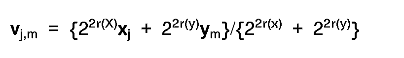
wobei r(x) und r(y) Übertragungsraten der die Kandidatvektoren x j bzw. y m repräsentierenden Codes sind. - Verfahren nach Anspruch 18, bei dem, wenn man das i-te Element des Eingangsvektors u und die g-ten Elemente der Kandidatvektoren x j und y m mit u(i), x(g,j) bzw. y(g,m) bezeichnet, der Schritt (b) ein Schritt ist, bei dem als die Verzerrung für die Kandidatvektoren x j und y m des ausgewählten Satzes eine Verzerrung dj,m berechnet wird, die durch die folgende Gleichung definiert ist:

Applications Claiming Priority (2)
| Application Number | Priority Date | Filing Date | Title |
|---|---|---|---|
| JP27538887 | 1987-10-30 | ||
| JP275388/87 | 1987-10-30 |
Publications (3)
| Publication Number | Publication Date |
|---|---|
| EP0314018A2 EP0314018A2 (de) | 1989-05-03 |
| EP0314018A3 EP0314018A3 (en) | 1990-05-30 |
| EP0314018B1 true EP0314018B1 (de) | 1993-09-01 |
Family
ID=17554798
Family Applications (1)
| Application Number | Title | Priority Date | Filing Date |
|---|---|---|---|
| EP88117612A Expired - Lifetime EP0314018B1 (de) | 1987-10-30 | 1988-10-21 | Verfahren und Vorrichtung für multiplexierte Vektorquantifizierung |
Country Status (4)
| Country | Link |
|---|---|
| US (1) | US4922508A (de) |
| EP (1) | EP0314018B1 (de) |
| CA (1) | CA1311060C (de) |
| DE (1) | DE3883701T2 (de) |
Cited By (5)
| Publication number | Priority date | Publication date | Assignee | Title |
|---|---|---|---|---|
| US9445120B2 (en) | 2011-04-12 | 2016-09-13 | Sun Patent Trust | Moving picture coding method, moving picture coding apparatus, moving picture decoding method, moving picture decoding apparatus and moving picture coding and decoding apparatus |
| US9456214B2 (en) | 2011-08-03 | 2016-09-27 | Sun Patent Trust | Moving picture coding method, moving picture coding apparatus, moving picture decoding method, moving picture decoding apparatus, and moving picture coding and decoding apparatus |
| US9456217B2 (en) | 2011-05-24 | 2016-09-27 | Sun Patent Trust | Coding method and apparatus with candidate motion vectors |
| US9560373B2 (en) | 2011-05-31 | 2017-01-31 | Sun Patent Trust | Image coding method and apparatus with candidate motion vectors |
| US11570444B2 (en) | 2011-05-27 | 2023-01-31 | Sun Patent Trust | Image coding method, image coding apparatus, image decoding method, image decoding apparatus, and image coding and decoding apparatus |
Families Citing this family (37)
| Publication number | Priority date | Publication date | Assignee | Title |
|---|---|---|---|---|
| JPH0783315B2 (ja) * | 1988-09-26 | 1995-09-06 | 富士通株式会社 | 可変レート音声信号符号化方式 |
| CA2002015C (en) * | 1988-12-30 | 1994-12-27 | Joseph Lindley Ii Hall | Perceptual coding of audio signals |
| DE69031186D1 (de) * | 1989-03-10 | 1997-09-11 | Canon Kk | Verfahren und Vorrichtung zum Codieren von Bildinformation |
| US5031037A (en) * | 1989-04-06 | 1991-07-09 | Utah State University Foundation | Method and apparatus for vector quantizer parallel processing |
| US4994927A (en) * | 1989-06-19 | 1991-02-19 | Gte Laboratories Inc | Self-adaptive neural net based vector quantizer for image compression |
| US5263119A (en) * | 1989-06-29 | 1993-11-16 | Fujitsu Limited | Gain-shape vector quantization method and apparatus |
| JPH0332228A (ja) * | 1989-06-29 | 1991-02-12 | Fujitsu Ltd | ゲイン―シェイプ・ベクトル量子化方式 |
| JPH0370336A (ja) * | 1989-08-10 | 1991-03-26 | Mitsubishi Electric Corp | ディジタル変調の波形データ修正方法 |
| US5072293A (en) * | 1989-08-29 | 1991-12-10 | U.S. Philips Corporation | Method of estimating motion in a picture signal |
| US5255346A (en) * | 1989-12-28 | 1993-10-19 | U S West Advanced Technologies, Inc. | Method and apparatus for design of a vector quantizer |
| US5253053A (en) * | 1990-12-31 | 1993-10-12 | Apple Computer, Inc. | Variable length decoding using lookup tables |
| JP3151874B2 (ja) * | 1991-02-26 | 2001-04-03 | 日本電気株式会社 | 音声パラメータ符号化方式および装置 |
| JPH0568243A (ja) * | 1991-09-09 | 1993-03-19 | Hitachi Ltd | 可変長符号化制御方式 |
| US5325126A (en) * | 1992-04-01 | 1994-06-28 | Intel Corporation | Method and apparatus for real time compression and decompression of a digital motion video signal |
| US5651026A (en) * | 1992-06-01 | 1997-07-22 | Hughes Electronics | Robust vector quantization of line spectral frequencies |
| US5388124A (en) * | 1992-06-12 | 1995-02-07 | University Of Maryland | Precoding scheme for transmitting data using optimally-shaped constellations over intersymbol-interference channels |
| US5467413A (en) * | 1993-05-20 | 1995-11-14 | Radius Inc. | Method and apparatus for vector quantization for real-time playback on low cost personal computers |
| JP2626492B2 (ja) * | 1993-09-13 | 1997-07-02 | 日本電気株式会社 | ベクトル量子化装置 |
| US5692100A (en) * | 1994-02-02 | 1997-11-25 | Matsushita Electric Industrial Co., Ltd. | Vector quantizer |
| US5517595A (en) * | 1994-02-08 | 1996-05-14 | At&T Corp. | Decomposition in noise and periodic signal waveforms in waveform interpolation |
| US5521988A (en) * | 1994-04-05 | 1996-05-28 | Gte Laboratories Incorporated | Vector transform coder with multi-layered codebooks and dynamic bit allocation |
| JP2956473B2 (ja) * | 1994-04-21 | 1999-10-04 | 日本電気株式会社 | ベクトル量子化装置 |
| US5822456A (en) * | 1994-07-14 | 1998-10-13 | Johnson-Grace | Optimal spline interpolation for image compression |
| MX9700385A (es) | 1994-07-14 | 1998-05-31 | Johnson Grace Company | Metodo y aparato para comprimir imagenes. |
| US5592227A (en) * | 1994-09-15 | 1997-01-07 | Vcom, Inc. | Method and apparatus for compressing a digital signal using vector quantization |
| US5636231A (en) * | 1995-09-05 | 1997-06-03 | Motorola, Inc. | Method and apparatus for minimal redundancy error detection and correction of voice spectrum parameters |
| US5889891A (en) * | 1995-11-21 | 1999-03-30 | Regents Of The University Of California | Universal codebook vector quantization with constrained storage |
| US5835037A (en) * | 1996-12-31 | 1998-11-10 | Iterated Systems, Inc. | Method and apparatus for modeling discrete data sequences by multiple vector representation |
| US6076055A (en) * | 1997-05-27 | 2000-06-13 | Ameritech | Speaker verification method |
| US7630895B2 (en) * | 2000-01-21 | 2009-12-08 | At&T Intellectual Property I, L.P. | Speaker verification method |
| DE69735262D1 (de) | 1997-11-24 | 2006-04-20 | St Microelectronics Srl | MPEG-2 Dekodierung mit reduziertem Speicherbedarf durch Rekomprimierung mit adaptiver baumstrukturierter Vektorquantisierung |
| JP4460903B2 (ja) * | 2004-01-20 | 2010-05-12 | 株式会社東芝 | 半導体ウェーハのidマーク認識方法 |
| US9485518B2 (en) | 2011-05-27 | 2016-11-01 | Sun Patent Trust | Decoding method and apparatus with candidate motion vectors |
| KR101889582B1 (ko) | 2011-05-31 | 2018-08-20 | 선 페이턴트 트러스트 | 동화상 부호화 방법, 동화상 부호화 장치, 동화상 복호화 방법, 동화상 복호화 장치, 및, 동화상 부호화 복호화 장치 |
| MY181718A (en) | 2011-06-30 | 2021-01-05 | Sun Patent Trust | Image decoding method, image encoding method, image decoding device, image encoding device, and image encoding/decoding device |
| CN103858428B (zh) | 2011-10-19 | 2018-07-03 | 太阳专利托管公司 | 图像编码方法、图像编码装置、图像解码方法及图像解码装置 |
| EP2873074A4 (de) | 2012-07-12 | 2016-04-13 | Nokia Technologies Oy | Vektorquantisierung |
Family Cites Families (7)
| Publication number | Priority date | Publication date | Assignee | Title |
|---|---|---|---|---|
| US4541012A (en) * | 1982-01-04 | 1985-09-10 | Compression Labs, Inc. | Video bandwidth reduction system employing interframe block differencing and transform domain coding |
| US4724535A (en) * | 1984-04-17 | 1988-02-09 | Nec Corporation | Low bit-rate pattern coding with recursive orthogonal decision of parameters |
| EP0227956B1 (de) * | 1985-12-04 | 1990-04-25 | Siemens Aktiengesellschaft | Verfahren zur Datenreduktion digitaler Bildsignale durch Vektorquantisierung |
| IT1184023B (it) * | 1985-12-17 | 1987-10-22 | Cselt Centro Studi Lab Telecom | Procedimento e dispositivo per la codifica e decodifica del segnale vocale mediante analisi a sottobande e quantizzazione vettorariale con allocazione dinamica dei bit di codifica |
| JP2527350B2 (ja) * | 1987-02-25 | 1996-08-21 | 富士写真フイルム株式会社 | ベクトル量子化による画像デ―タの圧縮および再構成装置 |
| US4805193A (en) * | 1987-06-04 | 1989-02-14 | Motorola, Inc. | Protection of energy information in sub-band coding |
| US4791654A (en) * | 1987-06-05 | 1988-12-13 | American Telephone And Telegraph Company, At&T Bell Laboratories | Resisting the effects of channel noise in digital transmission of information |
-
1988
- 1988-10-21 DE DE88117612T patent/DE3883701T2/de not_active Expired - Lifetime
- 1988-10-21 EP EP88117612A patent/EP0314018B1/de not_active Expired - Lifetime
- 1988-10-25 US US07/261,859 patent/US4922508A/en not_active Expired - Lifetime
- 1988-10-25 CA CA000581235A patent/CA1311060C/en not_active Expired - Lifetime
Cited By (5)
| Publication number | Priority date | Publication date | Assignee | Title |
|---|---|---|---|---|
| US9445120B2 (en) | 2011-04-12 | 2016-09-13 | Sun Patent Trust | Moving picture coding method, moving picture coding apparatus, moving picture decoding method, moving picture decoding apparatus and moving picture coding and decoding apparatus |
| US9456217B2 (en) | 2011-05-24 | 2016-09-27 | Sun Patent Trust | Coding method and apparatus with candidate motion vectors |
| US11570444B2 (en) | 2011-05-27 | 2023-01-31 | Sun Patent Trust | Image coding method, image coding apparatus, image decoding method, image decoding apparatus, and image coding and decoding apparatus |
| US9560373B2 (en) | 2011-05-31 | 2017-01-31 | Sun Patent Trust | Image coding method and apparatus with candidate motion vectors |
| US9456214B2 (en) | 2011-08-03 | 2016-09-27 | Sun Patent Trust | Moving picture coding method, moving picture coding apparatus, moving picture decoding method, moving picture decoding apparatus, and moving picture coding and decoding apparatus |
Also Published As
| Publication number | Publication date |
|---|---|
| EP0314018A2 (de) | 1989-05-03 |
| DE3883701D1 (de) | 1993-10-07 |
| CA1311060C (en) | 1992-12-01 |
| US4922508A (en) | 1990-05-01 |
| EP0314018A3 (en) | 1990-05-30 |
| DE3883701T2 (de) | 1994-02-10 |
Similar Documents
| Publication | Publication Date | Title |
|---|---|---|
| EP0314018B1 (de) | Verfahren und Vorrichtung für multiplexierte Vektorquantifizierung | |
| US5455874A (en) | Continuous-tone image compression | |
| US5014134A (en) | Image compression method and apparatus | |
| US5341442A (en) | Method and apparatus for compression data by generating base image data from luminance and chrominance components and detail image data from luminance component | |
| US5832443A (en) | Method and apparatus for adaptive audio compression and decompression | |
| US5034965A (en) | Efficient coding method and its decoding method | |
| US6215422B1 (en) | Digital signal huffman coding with division of frequency sub-bands | |
| KR20050008761A (ko) | 신호의 다중속도 격자 벡터 양자화를 위한 방법 및 시스템 | |
| US20030110027A1 (en) | Method and system for information signal coding using combinatorial and huffman codes | |
| KR19990023932A (ko) | 스위치식 예측 양자화 방법 | |
| JP2023522886A (ja) | ニューラルネットワークパラメーターの表現の改良された概念 | |
| US5825311A (en) | Vector coding method, encoder using the same and decoder therefor | |
| US5625744A (en) | Speech parameter encoding device which includes a dividing circuit for dividing a frame signal of an input speech signal into subframe signals and for outputting a low rate output code signal | |
| EP1995974B1 (de) | Methode für die durchführung der arithmetischen kodierung | |
| US4354057A (en) | Predictive signal coding with partitioned quantization | |
| JP3434260B2 (ja) | オーディオ信号符号化方法及び復号化方法、これらの装置及びプログラム記録媒体 | |
| EP4169166B1 (de) | Vorrichtungen zur codierung und decodierung einer folge von ganzzahligen werten, verfahren zur codierung und decodierung einer folge von ganzzahligen werten und computerprogramm zur implementierung dieser verfahren | |
| JPH0783316B2 (ja) | 多量ベクトル量子化方法及びその装置 | |
| EP0899720B1 (de) | Quantisierung der linearen Prädiktionskoeffizienten | |
| Xie et al. | Fast and low-complexity LSF quantization using algebraic vector quantizer | |
| US6665646B1 (en) | Predictive balanced multiple description coder for data compression | |
| EP0952572B1 (de) | Vorrichtung und Verfahren zur Vektorquantisierung | |
| WO2007058465A1 (en) | Methods and apparatuses to quantize and de-quantize linear predictive coding coefficient | |
| JP3272214B2 (ja) | 格子量子化器および入力ベクトルを格子量子化するための方法 | |
| JP3857820B2 (ja) | 画像圧縮装置および画像伸張装置 |
Legal Events
| Date | Code | Title | Description |
|---|---|---|---|
| PUAI | Public reference made under article 153(3) epc to a published international application that has entered the european phase |
Free format text: ORIGINAL CODE: 0009012 |
|
| 17P | Request for examination filed |
Effective date: 19881021 |
|
| AK | Designated contracting states |
Kind code of ref document: A2 Designated state(s): DE FR GB SE |
|
| PUAL | Search report despatched |
Free format text: ORIGINAL CODE: 0009013 |
|
| AK | Designated contracting states |
Kind code of ref document: A3 Designated state(s): DE FR GB SE |
|
| 17Q | First examination report despatched |
Effective date: 19920515 |
|
| GRAA | (expected) grant |
Free format text: ORIGINAL CODE: 0009210 |
|
| AK | Designated contracting states |
Kind code of ref document: B1 Designated state(s): DE FR GB SE |
|
| REF | Corresponds to: |
Ref document number: 3883701 Country of ref document: DE Date of ref document: 19931007 |
|
| ET | Fr: translation filed | ||
| PLBE | No opposition filed within time limit |
Free format text: ORIGINAL CODE: 0009261 |
|
| STAA | Information on the status of an ep patent application or granted ep patent |
Free format text: STATUS: NO OPPOSITION FILED WITHIN TIME LIMIT |
|
| 26N | No opposition filed | ||
| EAL | Se: european patent in force in sweden |
Ref document number: 88117612.7 |
|
| REG | Reference to a national code |
Ref country code: FR Ref legal event code: CA |
|
| REG | Reference to a national code |
Ref country code: GB Ref legal event code: IF02 |
|
| PGFP | Annual fee paid to national office [announced via postgrant information from national office to epo] |
Ref country code: DE Payment date: 20071030 Year of fee payment: 20 |
|
| PGFP | Annual fee paid to national office [announced via postgrant information from national office to epo] |
Ref country code: SE Payment date: 20071004 Year of fee payment: 20 |
|
| PGFP | Annual fee paid to national office [announced via postgrant information from national office to epo] |
Ref country code: GB Payment date: 20071017 Year of fee payment: 20 Ref country code: FR Payment date: 20070716 Year of fee payment: 20 |
|
| REG | Reference to a national code |
Ref country code: GB Ref legal event code: PE20 Expiry date: 20081020 |
|
| EUG | Se: european patent has lapsed | ||
| PG25 | Lapsed in a contracting state [announced via postgrant information from national office to epo] |
Ref country code: GB Free format text: LAPSE BECAUSE OF EXPIRATION OF PROTECTION Effective date: 20081020 |