EP0314090A2 - Voie miniature - Google Patents
Voie miniature Download PDFInfo
- Publication number
- EP0314090A2 EP0314090A2 EP88117813A EP88117813A EP0314090A2 EP 0314090 A2 EP0314090 A2 EP 0314090A2 EP 88117813 A EP88117813 A EP 88117813A EP 88117813 A EP88117813 A EP 88117813A EP 0314090 A2 EP0314090 A2 EP 0314090A2
- Authority
- EP
- European Patent Office
- Prior art keywords
- links
- toy
- current
- conductors
- train according
- Prior art date
- Legal status (The legal status is an assumption and is not a legal conclusion. Google has not performed a legal analysis and makes no representation as to the accuracy of the status listed.)
- Granted
Links
Images

Classifications
-
- A—HUMAN NECESSITIES
- A63—SPORTS; GAMES; AMUSEMENTS
- A63H—TOYS, e.g. TOPS, DOLLS, HOOPS OR BUILDING BLOCKS
- A63H18/00—Highways or trackways for toys; Propulsion by special interaction between vehicle and track
- A63H18/02—Construction or arrangement of the trackway
Definitions
- the innovation relates to a toy train with driving toys with an electric drive motor arranged in the chassis as well as a track section formed in particular from pluggably connected links.
- the object of the innovation in a toy train is to ensure uninterrupted driving operation by connecting it to the network over an arbitrarily long period of time and to continue driving operation in the event of failure or termination of the network connection over a subsequent predetermined period of time.
- this object is achieved in that the links releasably carry current conductors over the entire roadway, which are connected to the poles of a power supply device, that the toy vehicle has current collectors contacting the current conductors and a rechargeable current source serving as an electrical buffer, and that the current source and the pantographs are permanently connected to the drive motor at the same time.
- the driving toy is so z. B. over the duration of shop opening times by means of the power conductor to a voltage supplied by the power supply, which ensures an uninterrupted movement of the toy vehicle, while when the power supply device is disconnected, the internal power source is automatically used and a subsequent further driving operation until the emptying Power source allows. This leads to z. B.
- the power supply device is preferably designed such that it supplies a voltage which is substantially 50% higher than the operating voltage of the rechargeable internal power source.
- the current conductors can be held on the links in any way. It is intended to fix the current conductors to the limbs by means of adhesion.
- the current conductors can be formed by continuously applied band-shaped foils or by foil sections contacting one another made of a metallic material.
- the metal foils or metal foil sections are expediently designed to be self-adhesive, so that after the roadway has been erected, it can be equipped with current conductors in a particularly simple manner.
- the metal foils have connectors, to which electrical conductors connected to the power supply device can be connected.
- a connector z. B. serve in the links sheet metal parts. It is also conceivable to choose short film sections as connectors, which are connected to the current conductors stay in contact. It goes without saying that the connectors can also be designed in any other desired manner. The electrical conductors themselves can attack the connectors by soldering, clamping or the like.
- the current conductors are arranged in the traversed areas and / or on the lateral guide bodies of the link pieces. According to the arrangement of the current conductors, it is only necessary to assign appropriately shaped current collectors. Brushes, shaped wire parts or the like can serve as current collectors as desired.
- the current conductors are formed from molded parts made of an electrically conductive material by means of molded parts which can be clipped onto the links.
- the molded parts have spring tabs, each of which contacts the molded parts of adjacent links. It is understood that the molded parts can be easily plugged onto the guide body and can thus be held interchangeably.
- the molded parts are preferably held by clamping or by means of clamping members, but it is also conceivable to firmly connect the molded parts to the link pieces.
- the links have hollow guide bodies which are open at the bottom on both sides of the road surface, and that by Insertion of connecting elements provided with clamping bodies into the cavities of the guide body, link pieces can be fixed next to one another in multiple tracks and, by means of pins or lugs made of an electrically conductive material formed centrally between the clamp bodies, simultaneously permanently contact the current conductors of the fixed adjacent link pieces.
- a particularly simple design of the connecting elements is obtained when the clamping bodies and the pins are formed in one piece from an electrically conductive material. The contact can be made by simply contacting connecting members connected to the current conductors or by soldering, squeezing the connecting members with the pins.
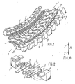
- the track section 1 can be formed by a plurality of link pieces 2 (FIG. 2).
- the links 2 have pins 3 and pliers-like recesses 4 for connection to one another, which embrace one another.
- Edge parts 5 on both sides next to the carriageway surface 8 serve as lateral guide bodies for driving toys 6.
- the carriageway 1 is provided over its entire length with current conductors 7 which, in the exemplary embodiments of FIGS. 1 to 5, are made from a flexible strip applied to the links 2 metallic material, for example a preferably self-adhesive metal foil are formed.
- the current conductors 7 are firmly but releasably connected to the link pieces 2.
- the current conductors 7 are arranged in the embodiment of FIGS.
- the current conductors 7 protrude Connector 9 '(Fig. 5) and electrical conductor 9 with a power supply device 10 in connection, which has a network transformer and a rectifier arrangement in a manner known per se.
- the driving toys take an internal power source 11, e.g. a rechargeable battery.
- an electric drive motor 12 is accommodated in the driving toy 6, which exerts a torque on the driving wheels 24 of the driving toy 6.
- the terminals 16, 17 of the drive motor are permanently connected to the poles 14 and 15 and the internal current source 11.
- the toy vehicle 6 carries pantographs 18, 19, which come into effect with the conductors 7.
- the current collectors 18, 19 are permanently connected to the poles 14 and 15 of the current source 11, respectively.
- the current collectors 18, 19 are formed by a brush arrangement, while in FIG. 4 spring wires serve as current collectors 18, 19 which protrude laterally from the toy vehicle and bear against the current conductors 7 with pretension.
- the current supply device 10 permanently charges the current source 11.
- the charging voltage is selected to be slightly greater than the operating voltage of the current source 11.
- the current collectors 18, 19 establish a connection via electrical conductors 20, 21 of the drive motor 6 with the power supply device 10 ago.
- the driving toy 6 can initially be operated as a network-operated driving toy on the roadway 1.
- the power source 11 acting as a buffer is charged.
- the roadway 1 can be traveled by means of the internal power source 11 by driving toys until the power source 11 is emptied in the shop window of a roadway exhibited this, eg after the evening closure of the point of sale, further driving movements of the driving toy 6 and thus advertising functions in the evening hours valuable for advertising.
- the current conductors 7 are formed by molded parts 7 ', which can each be pushed onto the edge parts 5 of the link pieces 2.
- the molded parts 7 ' have a substantially U-shaped clamping part 7', on each of which a contact tab 7 ′′′ is formed, which rests resiliently on the clamping part 7 'of the adjacent link 2 to form continuous current conductors 7.
- the molded parts 7 ' are applied in the area of the road surface 8 on the links.
- a connecting element 22 for links 2 to form multi-lane road sections is shown.
- the connecting element 22 has clamping bodies 22 ', which can be inserted from below into the open cavities of the edge parts 5 by clamping. Between the clamping bodies 22 ', the connecting element 22 has a projection 25 which is made of an electrically conductive material, e.g. Metal is formed and on which the current conductors 7 of the multi-lane carriageway sections 1 are fixed in a conductive manner. (Fig. 11)
- the current conductors 7 are applied to a carrier strip 23 which can be attached to the link pieces 2 together with the current conductors.
Landscapes
- Toys (AREA)
Priority Applications (1)
| Application Number | Priority Date | Filing Date | Title |
|---|---|---|---|
| AT88117813T ATE89760T1 (de) | 1987-10-27 | 1988-10-26 | Spielzeugbahn. |
Applications Claiming Priority (2)
| Application Number | Priority Date | Filing Date | Title |
|---|---|---|---|
| DE8714278U | 1987-10-27 | ||
| DE8714278U DE8714278U1 (de) | 1987-10-27 | 1987-10-27 | Spielzeugbahn |
Publications (3)
| Publication Number | Publication Date |
|---|---|
| EP0314090A2 true EP0314090A2 (fr) | 1989-05-03 |
| EP0314090A3 EP0314090A3 (en) | 1990-01-31 |
| EP0314090B1 EP0314090B1 (fr) | 1993-05-26 |
Family
ID=6813436
Family Applications (1)
| Application Number | Title | Priority Date | Filing Date |
|---|---|---|---|
| EP88117813A Expired - Lifetime EP0314090B1 (fr) | 1987-10-27 | 1988-10-26 | Voie miniature |
Country Status (4)
| Country | Link |
|---|---|
| US (1) | US5160091A (fr) |
| EP (1) | EP0314090B1 (fr) |
| AT (1) | ATE89760T1 (fr) |
| DE (2) | DE8714278U1 (fr) |
Cited By (2)
| Publication number | Priority date | Publication date | Assignee | Title |
|---|---|---|---|---|
| EP1692344A4 (fr) * | 2003-10-14 | 2007-04-11 | Battat Inc | Chenille souple pour vehicule jouet |
| US9061218B2 (en) | 2009-10-06 | 2015-06-23 | Tomy International, Inc. | Train tracks |
Families Citing this family (10)
| Publication number | Priority date | Publication date | Assignee | Title |
|---|---|---|---|---|
| US5868076A (en) * | 1996-02-28 | 1999-02-09 | Myus; David Allan | Slotless electric track for vehicles |
| US6328500B1 (en) | 2000-01-24 | 2001-12-11 | Tamara L. Rubio | Segmented toy roadway, toy roadway segment, and method of making same |
| US6382519B1 (en) * | 2000-05-22 | 2002-05-07 | Bong Kyu Choi | Assembling type unit track member for toy vehicles |
| USD481424S1 (en) | 2001-11-13 | 2003-10-28 | Learning Curve International, Inc. | Toy track segment |
| US6648237B2 (en) | 2001-11-13 | 2003-11-18 | Learning Curve International, Inc. | Toy vehicle track segment and method of manufacturing a toy vehicle track segment |
| US6935574B2 (en) * | 2003-11-12 | 2005-08-30 | Turbo Tec Company Limited | Toy-vehicle track section |
| JP4580289B2 (ja) * | 2005-06-28 | 2010-11-10 | 株式会社タカラトミー | 玩具用軌道 |
| US7959087B2 (en) * | 2006-12-08 | 2011-06-14 | Tarr Robert J | Model railroad track connector |
| US9682328B2 (en) | 2014-09-11 | 2017-06-20 | Honor Metro Limited | Toy vehicle track |
| US10267508B2 (en) * | 2016-11-04 | 2019-04-23 | Mindscope Products | Illuminated track system |
Family Cites Families (19)
| Publication number | Priority date | Publication date | Assignee | Title |
|---|---|---|---|---|
| US1511600A (en) * | 1922-09-27 | 1924-10-14 | Alan R Fergusson | Rail connecter for toy railways |
| US2171634A (en) * | 1938-02-07 | 1939-09-05 | Marx & Co Louis | Track and vehicle toy |
| JPS5219397U (fr) * | 1975-07-29 | 1977-02-10 | ||
| US4095743A (en) * | 1976-01-26 | 1978-06-20 | Birdsall John D | Flexible track for electrically energized miniature vehicles |
| US4139071A (en) * | 1976-02-27 | 1979-02-13 | Unep3 Energy Systems, Inc. | Electrically operated vehicle and electrified roadway therefor |
| US4078798A (en) * | 1976-12-06 | 1978-03-14 | Ideal Toy Corporation | Toy vehicle |
| US4179066A (en) * | 1978-02-10 | 1979-12-18 | The Quaker Oats Company | Means for joining toy track sections |
| US4217727A (en) * | 1978-07-31 | 1980-08-19 | Rosabelle Fetty | Miniature monorail system |
| DE2843429A1 (de) * | 1978-10-05 | 1980-04-24 | Fischer Artur Dr H C | Elektrisches anschlusselement fuer eine spieleisenbahn |
| US4241875A (en) * | 1979-01-19 | 1980-12-30 | Aurora Products Canada Limited | Flexible track |
| GB2055593B (en) * | 1979-08-08 | 1983-03-16 | Refined Ind Co Ltd | Toy vehicle tracks |
| US4352329A (en) * | 1980-04-21 | 1982-10-05 | Fetty Warren N | Toy roadway system |
| DE3132527A1 (de) * | 1981-08-18 | 1983-03-10 | Neuhierl, Hermann, Dipl.-Chem. Dr., 8510 Fürth | "bahnstueck fuer bahngebundene spielfahrzeuge" |
| US4632038A (en) * | 1984-04-30 | 1986-12-30 | Lawrence David L | Monorail vehicular system |
| DE3440875C2 (de) * | 1984-11-08 | 1986-11-27 | Hesse, Kurt, 8500 Nürnberg | Bahnstück einer flexiblen Fahrbahn |
| DE3524104C2 (de) * | 1985-07-05 | 1994-10-20 | Kurt Hesse | Fahrbahn für Fahrspielzeuge |
| US4697812A (en) * | 1985-12-09 | 1987-10-06 | Elliot Rudell | Off-road slot car and track system |
| EP0313675A1 (fr) * | 1987-10-27 | 1989-05-03 | Kurt Hesse | Voie de conduite pour véhicules jouets |
| US4941610A (en) * | 1988-06-24 | 1990-07-17 | Irwin Toy Limited | Construction piece for toy vehicle track |
-
1987
- 1987-10-27 DE DE8714278U patent/DE8714278U1/de not_active Expired
-
1988
- 1988-10-26 EP EP88117813A patent/EP0314090B1/fr not_active Expired - Lifetime
- 1988-10-26 AT AT88117813T patent/ATE89760T1/de not_active IP Right Cessation
- 1988-10-26 DE DE8888117813T patent/DE3881334D1/de not_active Expired - Fee Related
-
1991
- 1991-09-04 US US07/754,297 patent/US5160091A/en not_active Expired - Fee Related
Cited By (2)
| Publication number | Priority date | Publication date | Assignee | Title |
|---|---|---|---|---|
| EP1692344A4 (fr) * | 2003-10-14 | 2007-04-11 | Battat Inc | Chenille souple pour vehicule jouet |
| US9061218B2 (en) | 2009-10-06 | 2015-06-23 | Tomy International, Inc. | Train tracks |
Also Published As
| Publication number | Publication date |
|---|---|
| US5160091A (en) | 1992-11-03 |
| ATE89760T1 (de) | 1993-06-15 |
| DE3881334D1 (de) | 1993-07-01 |
| DE8714278U1 (de) | 1989-02-16 |
| EP0314090B1 (fr) | 1993-05-26 |
| EP0314090A3 (en) | 1990-01-31 |
Similar Documents
| Publication | Publication Date | Title |
|---|---|---|
| EP0314090A2 (fr) | Voie miniature | |
| EP0632539A2 (fr) | Unité d'alimentation enfichable pour appareillage électrique | |
| EP2255991A2 (fr) | Rail conducteur | |
| DE1954428C3 (de) | Spielzeuggleisbausatz für aus zusammensetzbaren Einzelbauteilen zu bildende Spielzeugeisenbahngleise aus Kunststoff | |
| DE69320659T2 (de) | Stromschiene | |
| EP0313675A1 (fr) | Voie de conduite pour véhicules jouets | |
| DE3800568C2 (fr) | ||
| DE2056663A1 (de) | Spielzeugbahn | |
| DE2251731A1 (de) | Verbindungsteil fuer stromschienen | |
| EP0207187B1 (fr) | Piste pour véhicules jouets | |
| EP0308534B1 (fr) | Circuit permettant le libre déplacement et/ou le guidage par la piste d'un véhicule jouet | |
| DE3510369C2 (fr) | ||
| DE2906309A1 (de) | Schleifkontakt fuer eine spieleisenbahn | |
| EP0105538A1 (fr) | Prise de courant ou prise multiple en matière plastique | |
| DE19606921A1 (de) | Spielzeugbahn (Spurbahn) | |
| DE2211468A1 (de) | Steuereinrichtung fuer spielzeugoder modellfahrzeuge | |
| DE3702044C2 (de) | Fahrspielzeug | |
| DE3802913C2 (de) | Elektrische Steckverbindung zum Anschluß von Drähten an Schienen von Modelleisenbahnen | |
| DE2939382A1 (de) | Klemmleiste mit schneidsteckverbinderelementen | |
| DE2514268A1 (de) | Spielzeugschiene fuer elektrisch angetriebene spielzeuge wie autos oder eisenbahnzuege | |
| CH271673A (de) | Doppelte Kreuzweiche für elektrische Spielzeugeisenbahnen. | |
| DE19729035B4 (de) | Kraftfahrzeugmodellanlage mit elektromotorisch angetriebenen Spielfahrzeugen | |
| AT243656B (de) | Fahrbahnabschnitt für elektrisch betriebene Modell- oder Spielfahrzeuge | |
| EP1759748A2 (fr) | Système d'entraînement magnétique pour des modeles reduit | |
| DE3119678A1 (de) | Anordnung aus einer skihaltevorrichtung und skiern |
Legal Events
| Date | Code | Title | Description |
|---|---|---|---|
| PUAI | Public reference made under article 153(3) epc to a published international application that has entered the european phase |
Free format text: ORIGINAL CODE: 0009012 |
|
| AK | Designated contracting states |
Kind code of ref document: A2 Designated state(s): AT BE CH DE ES FR GB GR IT LI LU NL SE |
|
| PUAL | Search report despatched |
Free format text: ORIGINAL CODE: 0009013 |
|
| AK | Designated contracting states |
Kind code of ref document: A3 Designated state(s): AT BE CH DE ES FR GB GR IT LI LU NL SE |
|
| 17P | Request for examination filed |
Effective date: 19900315 |
|
| 17Q | First examination report despatched |
Effective date: 19901210 |
|
| GRAA | (expected) grant |
Free format text: ORIGINAL CODE: 0009210 |
|
| AK | Designated contracting states |
Kind code of ref document: B1 Designated state(s): AT BE CH DE ES FR GB GR IT LI LU NL SE |
|
| PG25 | Lapsed in a contracting state [announced via postgrant information from national office to epo] |
Ref country code: NL Effective date: 19930526 Ref country code: IT Free format text: LAPSE BECAUSE OF FAILURE TO SUBMIT A TRANSLATION OF THE DESCRIPTION OR TO PAY THE FEE WITHIN THE PRE;WARNING: LAPSES OF ITALIAN PATENTS WITH EFFECTIVE DATE BEFORE 2007 MAY HAVE OCCURRED AT ANY TIME BEFORE 2007. THE CORRECT EFFECTIVE DATE MAY BE DIFFERENT FROM THE ONE RECORDED.SCRIBED TIME-LIMIT Effective date: 19930526 Ref country code: GB Effective date: 19930526 Ref country code: ES Free format text: THE PATENT HAS BEEN ANNULLED BY A DECISION OF A NATIONAL AUTHORITY Effective date: 19930526 Ref country code: GR Free format text: LAPSE BECAUSE OF FAILURE TO SUBMIT A TRANSLATION OF THE DESCRIPTION OR TO PAY THE FEE WITHIN THE PRESCRIBED TIME-LIMIT Effective date: 19930526 Ref country code: FR Effective date: 19930526 Ref country code: SE Effective date: 19930526 Ref country code: BE Effective date: 19930526 |
|
| REF | Corresponds to: |
Ref document number: 89760 Country of ref document: AT Date of ref document: 19930615 Kind code of ref document: T |
|
| REF | Corresponds to: |
Ref document number: 3881334 Country of ref document: DE Date of ref document: 19930701 |
|
| EN | Fr: translation not filed | ||
| PG25 | Lapsed in a contracting state [announced via postgrant information from national office to epo] |
Ref country code: AT Effective date: 19931026 |
|
| PG25 | Lapsed in a contracting state [announced via postgrant information from national office to epo] |
Ref country code: LI Effective date: 19931031 Ref country code: CH Effective date: 19931031 Ref country code: LU Free format text: LAPSE BECAUSE OF NON-PAYMENT OF DUE FEES Effective date: 19931031 |
|
| NLV1 | Nl: lapsed or annulled due to failure to fulfill the requirements of art. 29p and 29m of the patents act | ||
| GBV | Gb: ep patent (uk) treated as always having been void in accordance with gb section 77(7)/1977 [no translation filed] |
Effective date: 19930526 |
|
| PLBE | No opposition filed within time limit |
Free format text: ORIGINAL CODE: 0009261 |
|
| STAA | Information on the status of an ep patent application or granted ep patent |
Free format text: STATUS: NO OPPOSITION FILED WITHIN TIME LIMIT |
|
| 26N | No opposition filed | ||
| REG | Reference to a national code |
Ref country code: CH Ref legal event code: PL |
|
| PG25 | Lapsed in a contracting state [announced via postgrant information from national office to epo] |
Ref country code: DE Effective date: 19940701 |