EP0314097B1 - Gerät zur optischen Heterodyn/Homodyndetektion - Google Patents
Gerät zur optischen Heterodyn/Homodyndetektion Download PDFInfo
- Publication number
- EP0314097B1 EP0314097B1 EP88117835A EP88117835A EP0314097B1 EP 0314097 B1 EP0314097 B1 EP 0314097B1 EP 88117835 A EP88117835 A EP 88117835A EP 88117835 A EP88117835 A EP 88117835A EP 0314097 B1 EP0314097 B1 EP 0314097B1
- Authority
- EP
- European Patent Office
- Prior art keywords
- signal
- frequency
- light
- local oscillation
- polarization
- Prior art date
- Legal status (The legal status is an assumption and is not a legal conclusion. Google has not performed a legal analysis and makes no representation as to the accuracy of the status listed.)
- Expired - Lifetime
Links
- 238000001514 detection method Methods 0.000 title claims description 29
- 230000003287 optical effect Effects 0.000 title claims description 26
- 230000010287 polarization Effects 0.000 claims description 57
- 230000010355 oscillation Effects 0.000 claims description 50
- 238000010408 sweeping Methods 0.000 claims description 3
- 239000013307 optical fiber Substances 0.000 description 4
- 230000005540 biological transmission Effects 0.000 description 3
- 230000001427 coherent effect Effects 0.000 description 3
- 230000001419 dependent effect Effects 0.000 description 3
- 230000006641 stabilisation Effects 0.000 description 3
- 238000011105 stabilization Methods 0.000 description 3
- 230000000087 stabilizing effect Effects 0.000 description 3
- 238000010586 diagram Methods 0.000 description 2
- 230000005684 electric field Effects 0.000 description 2
- 229910003327 LiNbO3 Inorganic materials 0.000 description 1
- 230000003111 delayed effect Effects 0.000 description 1
- 238000005516 engineering process Methods 0.000 description 1
- 239000004065 semiconductor Substances 0.000 description 1
- 230000035945 sensitivity Effects 0.000 description 1
Images

Classifications
-
- H—ELECTRICITY
- H04—ELECTRIC COMMUNICATION TECHNIQUE
- H04B—TRANSMISSION
- H04B10/00—Transmission systems employing electromagnetic waves other than radio-waves, e.g. infrared, visible or ultraviolet light, or employing corpuscular radiation, e.g. quantum communication
- H04B10/60—Receivers
-
- H—ELECTRICITY
- H04—ELECTRIC COMMUNICATION TECHNIQUE
- H04B—TRANSMISSION
- H04B10/00—Transmission systems employing electromagnetic waves other than radio-waves, e.g. infrared, visible or ultraviolet light, or employing corpuscular radiation, e.g. quantum communication
- H04B10/60—Receivers
- H04B10/61—Coherent receivers
- H04B10/615—Arrangements affecting the optical part of the receiver
- H04B10/6151—Arrangements affecting the optical part of the receiver comprising a polarization controller at the receiver's input stage
-
- H—ELECTRICITY
- H04—ELECTRIC COMMUNICATION TECHNIQUE
- H04B—TRANSMISSION
- H04B10/00—Transmission systems employing electromagnetic waves other than radio-waves, e.g. infrared, visible or ultraviolet light, or employing corpuscular radiation, e.g. quantum communication
- H04B10/60—Receivers
- H04B10/61—Coherent receivers
- H04B10/63—Homodyne, i.e. coherent receivers where the local oscillator is locked in frequency and phase to the carrier signal
-
- H—ELECTRICITY
- H04—ELECTRIC COMMUNICATION TECHNIQUE
- H04B—TRANSMISSION
- H04B10/00—Transmission systems employing electromagnetic waves other than radio-waves, e.g. infrared, visible or ultraviolet light, or employing corpuscular radiation, e.g. quantum communication
- H04B10/60—Receivers
- H04B10/61—Coherent receivers
- H04B10/64—Heterodyne, i.e. coherent receivers where, after the opto-electronic conversion, an electrical signal at an intermediate frequency [IF] is obtained
Definitions
- the invention relates to an optical heterodyne homodyne detection apparatus, and more particularly to an optical heterodyne homodyne detection apparatus in which polarizations of signal light and/or local oscillation light are scrambled to coincide with each other.
- An optical heterodyne detection communication system in which a coherent light optical fiber is used has an advantage that a long distance and high density transmission can be performed because the receiving sensitivity is remarkably high, and the frequency utilizing efficiency is also high, as compared to a direct detection communication system in which an intensity of light is modulated.
- the optical heterodyne detection communication system is described in a report entitled "A coherent light optical fiber transmission demodulation technology - FSK heterodyne detection" in "The Practical Report, Vol 31, No. 12, 1982" published by Nippon Telegraph and Telephone Corp.
- signal light supplied from an optical transmitter is coupled with light supplied from a local oscillation light source to provide combined light which is then received in an optical detector.
- a beat signal corresponding to the difference or frequencies between the signal light and the local oscillation light is produced in the optical detector as an electric signal of intermediate frequency.
- the intermediate frequency signal is demodulated to produce the base band signal.
- the frequency and polarization of the local oscillation light are controlled to synchronize with the fluctuation of the center frequency and polarization of the signal light.
- Such a control for the stabilization of the frequency and level of the intermediate frequency signal is also adopted in a freqency division multiplexed transmission system. That is, the frequency sweep of local oscillation light is performed to pull the beat signal of a predetermined channel into an intermediate frequency band, and the above mentioned frequency and polarization control is then performed in a case where the predetermined channel is selectively received from frequency division multiplexed signals.
- the beat signal of a first channel to which a second channel is changed-over is not detected, thereby making it impossible to pull the beat signal into the intermediate frequency band, even if the frequency sweep of the local oscillation light is performed to change-over from the second channel to the first channel.
- the probability of not detecting the beat signal is increased in proportional to the number of channels.
- an optical heterodyne homodyne detection apparatus comprises a frequency sweeping means for a local oscillation light source, a polarization scrambling means for local oscillation light and/or signal light, a polarization angle control means for the local oscillation light and/or the signal light, an intermediate frequency signal producing means, and a controller for the above described means.
- the frequency sweeping means and the polarization scrambling means are controlled by the controller, so that the frequency sweep and the polarization scrambling are performed, and stopped when the frequency of the intermediate frequency signal assumes a predetermined value. Thereafter, the polarization angle control is performed to coincide the polarizations of the signal and local oscillation lights.
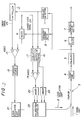
- FIG. 1 there is shown an optical heterodyne detection apparatus or 10 channel frequency division multiplexed frequency shift keying in the first embodiment according to the invention.
- the optical heterodyne detection apparatus comprises an optical coupler 3 for combining signal light 1 and local oscillation light 2, a front end 4 of a PIN-FET optical detector, an equalizer 5, an IF filter 6, and a demodulation circuit 7.
- the local oscillation light 2 is supplied through a polarization controller 22 from a local oscillation light source 21.
- the local oscillation light source 21 is controlled by a first control system including a voltage sweep circuit 14 connected to a controller 12, a switch 9 to which the output of a frequency discriminator 8 is applied, a first adder 15 to which the voltage sweep circuit 14 and the switch 9 are connected, and a current source 18.
- the voltage sweep circuit 14 holds the output voltage at a very moment when a sweep signal 23 supplied from the controller 12 is "0".
- the polarization controller 22 is controlled by a second control system including a maximum value control circuit 16 to which the output of an envelope detection circuit 11 is supplied, an oscillator 17, a second adder 19 to which the maximum value control circuit 16 and the oscillator 17 are connected, a first driver 20 to which the second adder 19 is connected, and a second driver 25 to which the maximum value control circuit 16 is connected.
- the controller 12 is supplied with the outputs of a channel discrimination circuit 10, the envelope detection circuit 11, and an input terminal 13, so that the sweep signal 23 and a change-over signal 24 are produced in the controller 12.
- the frequency division multiplexed signal light 1 of 10 channels is supplied through a single mode optical fiber from an optical transmitter (not shown), the signal light is combined in the optical coupler 3 with the local oscillation light 2.
- the combined light is supplied to the front end 4 and converted therein to electric signals.
- the intermediate frequency signal which is output of the front end 4 is the beat signal of a channel selected from the 10 channels, and is equalized in the equalizer 5.
- the intermediate frequency signal thus equalized is divided into three signals supplied to the IF filter 6, the frequency discriminator 8, and the envelope detection circuit 17 respectively.
- One of the three signals is passed through the IF filter 6 in which noise is removed from the signal, and the base band signal is obtained in the demodulator 7 in accordance with the demodulation thereof.
- the envelope detection circuit 11 which is a power detection circuit utilizing a square characteristic of a double-balanced mixer, the presence and non-presence of the intermediate frequency signal is detected, and the power of the intermediate frequency signal is detected in case of the presence thereof.
- the output of the envelope detection circuit 11 is supplied to the controller 12 and the maximum value control circuit 16.
- the frequency fluctuation of the intermediate frequency signal is detected in the frequency discriminator 8 which is composed of delayed lines and a mixer.
- a stabilizing control signal for suppressing the frequency fluctuation is produced to be supplied through the switch 9 to the first adder 15.
- a channel discrimination signal is picked out of the demodulated signal, and is supplied to the controller 12, together with the signal supplied from the input terminal 13 for selecting one of the 10 channels and the signal supplied from the envelope detection circuit 11 for informing about the presence and non-presence of the intermediate frequency signal.
- the controller 12 produces the sweep signal 23 and the change-over signal 24 dependent on the supplied signals.
- the sweep signal 23 is a trigger signal for driving the voltage sweep circuit 14 by which the frequency sweep of the local oscillation light source 21 composed of a variable wavelength semiconductor laser is performed, while the change-over signal 24 is a signal for turning the switch 9 on and off in the first control system by which the frequency of the intermediate frequency signal is stabilized, and is a signal for performing the polarization scrambling in the second control system.
- the sweep signal 23 is supplied from the controller 12 to the voltage sweep circuit 14, the output of which is added in the first adder 15 to the control signal for stabilizing the intermediate frequency.
- the output of the first adder 15 is converted in the current source 18 to a current signal which is then added to a bias current of the local oscillation light source 21.
- the frequency of the intermediate frequency signal is controlled to be changed dependent on the output of the first adder 15 because the frequency of the local oscillation light source 21 is changed dependent on the bias current. In the embodiment, it takes one second to sweep the frequency of the local oscillation light source 21 in the whole frequency band of the 10 channel signal light 1.
- the change-over signal 24 is supplied to the switch 9 and the oscillator 17, so that the switch 9 is turned on, and the output of the oscillator 17 is ceased to be supplied therefrom when the change-over signal is "1", while the switch 9 is turned off, and the output of the oscillator 17 is supplied to the second adder 19 when the change-over signal is "0".
- the output of the oscillator 17 is added in the second adder 19 to a first output of the maximum value control circuit 16.
- the first output is a signal for controlling a polarization angle of the local oscillation light 2. Therefore, a signal which is a sinusoidal wave for vibrating the polarization angle of the local oscillation light 2 is supplied from the second adder 19 to the driver 20 when the oscillator 17 is turned on to produce the oscillation signal of, for instance, 10 KHz.
- the voltage of the polarization controller 22, which is of an electric field rotation type of an optical LiNbO3 waveguide structure, is increased in its output amplitude up to more than 6 V.
- a second output of the maximum value control circuit 16 which is a signal for controlling an elliptic function of the local oscillation light 2, is supplied to the second driver 25 by which the voltage of the polarization controller 22 is increased.
- the polarization controller 22 comprises first and second regions in which the first region acts as a ⁇ /2 plate, and the second region acts as a ⁇ /4 plate, where ⁇ is a wavelength of light. In each region, electrodes are provided along a waveguide, so that an electric field is applied thereto by 360 degrees.
- the output of the first driver 20 is applied to the electrode of the first region for the ⁇ /2 plate
- the output of the second driver 25 is applied to the electrode of the second region for the ⁇ /4 plate.
- the local oscillation light 2 of the local oscillation light source 21 is controlled to have a predetermined polarization, and the polarization scrambling is conducted in the frequency of 10 KHz (as described in the reports published by the "Institute of Electronics Information and Communications Engineers" 85/2, vol. J68 - CNo. 2).
- a signal of the predetermined channel (hereinafter called “input channel”) is supplied from the input terminal 13 to the controller 12. It is determined in the controller 12 how far and on which side of high or low frequency the input channel is in regard to the presently selected channel, a signal of which is supplied to the controller 12 from the channel discrimination circuit 10. In accordance with the determination of the controller 12, the sweep signal 23 which is "+1"v in a case where the input channel is on the side of high frequency, and is "-1"v in a case where the input channel is on the side of low frequency is supplied to the voltage sweep circuit 14 together with the change-over signal 24 of "0".
- the polarization of the local oscillation light 2 is scrambled, and the frequency thereof is swept in the direction of a predetermined frequency.
- the output of the envelope detection circuit 11 is monitored by the controller 12 to count the number of channel sweeps.
- the local oscillation light 2 is under the polarization scrambling as described above, so that the number of the channels is precisely counted because the intermediate frequencies can be detected in all of the 10 channels.
- the sweep signal 23 becomes "0"v
- the change-over signal 24 becomes "1".
- the voltage sweep circuit 14 holds the present output voltage so that the frequency sweep of the intermediate frequency signal is no longer performed.
- the polarization scrambling of the local oscillation light 2 is stopped, and the frequency stabilization of the intermediate frequency signal begins to operate.
- a level of the intermediate frequency signal is maximized in accordance with the polarization control signal of the local oscillation light 2 supplied from the maximum value control circuit 16. Consequently, signals of the input channel are obtained from the demodulator 7.
- the polarization scrambling is continued until the intermediate frequency assumes a predetermined frequency in accordance with the frequency sweep control of the local oscillation light.
- the polarization scrambling is controlled to stop, and the polarizations of the signal light and the local oscillation light are coincided with each other.
- the polarization of the local oscillation light is scrambled in the first embodiment.
- the polarization of the signal light may also be scrambled.
- Fig. 2 there is shown an optical heterodyne detection apparatus in the second embodiment according to the invention.
- the optical heterodyne detection apparatus which is applied to an optical frequency shift keying heterodyne detection communication system using a burst signal, like parts are indicated by like reference numerals in Fig. 2.
- the signal light 1 having a bit rate of 400 Mb/s and a modulation index of 2 is transmitted as a burst signal
- the signal light is combined in the optical coupler 3 with local oscillation light 2, and the combined light is received in the front end 4.
- the sweep signal 23 is supplied from the controller 12 to the first adder 15.
- the sweep signal 23 has a frequency of 100 Hz, and is to sweep the frequency of the local oscillation light 2 in a predetermined range of 5 GHz repeatedly.
- the change-over signal 24 which is supplied from the controller 12 is the same as the change-over signal 24 in the first embodiment.
- the optical heterodyne detection apparatus as shown in Fig. 2 operates in the same manner as in that of Fig.
- the polarization controller 22 is positioned on a light path for the local oscillation light 2 supplied from the local oscillation light source 21.
- the frequency of the local oscillation light 2 is swept in a range of 5 GHz, and the polarization scrambling thereof is performed.
- the intermediate frequency signal is detected in the envelope detection circuit 11, the frequency sweep and the polarization scrambling of the local oscillation light 2 are stopped, and the frequency stabilization of the intermediate frequency signal and the polarization control begin to be performed.
- the polarization control is also the same as in the first embodiment. Consequently, the frequency of the intermediate frequency signal is pulled into an intermediate frequency band to demodulate base band signals without depending on the polarization state of the local oscillation light 2.
- the polarization controller is of a waveguide type, it may be of an optical fiber type, a combination type of a ⁇ /2 plate and a ⁇ /4 plate, and so on.
- the polarization control and the polarization scrambling are performed in a common polarization controller, a polarization controller and a polarization scrambler may be provided separately.
- the arrangements in the first and second embodiments are most advantageous in regard to the minimization of loss.
- the polarization controller may be positioned on a light path of the signal light.
- the intermediate frequency is stabilized at a predetermined frequency because one of the polarizations is scrambled so that the beat signal can be detected.
Landscapes
- Physics & Mathematics (AREA)
- Electromagnetism (AREA)
- Engineering & Computer Science (AREA)
- Computer Networks & Wireless Communication (AREA)
- Signal Processing (AREA)
- Optical Communication System (AREA)
Claims (2)
- Gerät zur optischen Heterodyn-/Homodyndetektion mit:
einer Einrichtung (14) zum Ablenken der Frequenz von lokalem Oszillationslicht (2), einer Einrichtung (14, 24) zum Verwürfeln der Polarisation mindestens eines Lichts, ausgewählt aus dem lokalen Oszillationslicht und Signallicht (1), das von einem optischen Sender zugeführt wird,
einer Einrichtung (22) zum Steuern des Polarisationswinkels mindestens des einen Lichts,
einer Einrichtung (3) zum Erzeugen eines Zwischenfrequenzsignals durch Kombinieren des lokalen Oszillationslichts und des Signallichts und
einer Steuerung (12) zum Steuern der Frequenzablenkung des lokalen Oszillationslichts, der Polarisationsverwürfelung mindestens des einen Lichts und der Polarisationswinkelsteuerung mindestens des einen Lichts,
wobei die Frequenzablenkung und die Polarisationsverwürfelung unter Kontrolle der Steuerung durchgeführt und gestoppt werden, wenn die Frequenz des Zwischenfrequenzsignals einen vorbestimmten Wert annimmt, wonach die Polarisationswinkelsteuerung unter Kontrolle der Steuerung durchgeführt wird, um die Deckungsgleichheit der Polarisationen zwischen dem lokalen Oszillationslicht und dem Signallicht herzustellen. - Gerät zur optischen Heterodyn-/Homodyndetektion nach Anspruch 1, ferner mit:
einer Hüllkurvendetektionsschaltung (11) zum Detektieren des Vorhandenseins und Nichtvorhandenseins des Zwischenfrequenzsignals,
einer Kanaldiskriminationsschaltung (10) zum Diskriminieren von Kanälen und
einem Frequenzdiskriminator (8) zum Detektieren der Frequenzschwankung des Zwischenfrequenzsignals,
wobei die Frequenzablenkung und die Polarisationsverwürfelung in Übereinstimmung mit Signalen gesteuert werden, die von der Hüllkurvendetektionsschaltung und der Kanaldiskriminationsschaltung zu der Steuerung geführt werden, und
die Frequenz des Zwischenfrequenzsignals in Übereinstimmung mit Signalen stabilisiert wird, die von dem Frequenzdiskriminator zu einer lokalen Oszillationslichtquelle für das lokale Oszillationslicht geführt werden.
Applications Claiming Priority (2)
| Application Number | Priority Date | Filing Date | Title |
|---|---|---|---|
| JP271224/87 | 1987-10-27 | ||
| JP62271224A JPH063511B2 (ja) | 1987-10-27 | 1987-10-27 | 光ヘテロダイン・ホモダイン検波方法 |
Publications (3)
| Publication Number | Publication Date |
|---|---|
| EP0314097A2 EP0314097A2 (de) | 1989-05-03 |
| EP0314097A3 EP0314097A3 (en) | 1990-08-29 |
| EP0314097B1 true EP0314097B1 (de) | 1994-06-01 |
Family
ID=17497080
Family Applications (1)
| Application Number | Title | Priority Date | Filing Date |
|---|---|---|---|
| EP88117835A Expired - Lifetime EP0314097B1 (de) | 1987-10-27 | 1988-10-26 | Gerät zur optischen Heterodyn/Homodyndetektion |
Country Status (4)
| Country | Link |
|---|---|
| US (1) | US4903342A (de) |
| EP (1) | EP0314097B1 (de) |
| JP (1) | JPH063511B2 (de) |
| DE (1) | DE3889846T2 (de) |
Families Citing this family (16)
| Publication number | Priority date | Publication date | Assignee | Title |
|---|---|---|---|---|
| JP2540935B2 (ja) * | 1989-03-16 | 1996-10-09 | 日本電気株式会社 | 一括偏波制御方法 |
| JPH0362746A (ja) * | 1989-07-31 | 1991-03-18 | Nec Corp | 中間周波数引き込み方法及び装置 |
| IT1238535B (it) * | 1989-11-14 | 1993-08-18 | Cselt Centro Studi Lab Telecom | Sistema di comunicazione coerente in fibra ottica a diversita' di polarizzazione in trasmissione |
| JPH03214939A (ja) * | 1990-01-19 | 1991-09-20 | Nec Corp | チャンネル識別受信方法 |
| US5159481A (en) * | 1990-09-14 | 1992-10-27 | Bell Communications Research, Inc. | Polarization scrambler for polarization-sensitive optical devices |
| GB2264834A (en) * | 1992-02-25 | 1993-09-08 | Northern Telecom Ltd | Optical transmission system |
| JPH05303128A (ja) * | 1992-04-27 | 1993-11-16 | Nec Corp | イメージ信号除去光ヘテロダイン検波受信装置 |
| JP2826436B2 (ja) * | 1993-04-02 | 1998-11-18 | 日本電気株式会社 | 中間周波数引き込み方法 |
| US6671056B2 (en) * | 2001-01-11 | 2003-12-30 | Agilent Technologies, Inc | Method and system for optical spectrum analysis with a depolarized local oscillator signal |
| CA2419357C (en) | 2002-02-22 | 2007-07-24 | Nippon Telegraph And Telephone Corporation | Polarization scrambler and optical network using the same |
| KR100830694B1 (ko) | 2007-05-22 | 2008-05-19 | 광주과학기술원 | 광학식 호모다인 간섭계의 전자식 헤테로다인 간섭계로의변환방법 및 이를 이용한 간섭계 |
| JP4565256B2 (ja) * | 2008-07-22 | 2010-10-20 | 独立行政法人情報通信研究機構 | 偏光方向同期検出回路及び受信装置 |
| US8401399B2 (en) | 2009-05-28 | 2013-03-19 | Freedom Photonics, Llc. | Chip-based advanced modulation format transmitter |
| US9344196B1 (en) | 2009-05-28 | 2016-05-17 | Freedom Photonics, Llc. | Integrated interferometric optical transmitter |
| JP5549333B2 (ja) * | 2010-04-07 | 2014-07-16 | 富士通株式会社 | 偏波変動補償装置および光通信システム |
| US10320152B2 (en) | 2017-03-28 | 2019-06-11 | Freedom Photonics Llc | Tunable laser |
Family Cites Families (3)
| Publication number | Priority date | Publication date | Assignee | Title |
|---|---|---|---|---|
| GB8514264D0 (en) * | 1985-06-06 | 1985-07-10 | British Telecomm | Coherent optical receivers |
| JP3729936B2 (ja) * | 1996-06-13 | 2005-12-21 | 本田技研工業株式会社 | 車両のスライドドアのドアロック機構 |
| JPH101130A (ja) * | 1996-06-18 | 1998-01-06 | Toppan Printing Co Ltd | 液体用紙容器 |
-
1987
- 1987-10-27 JP JP62271224A patent/JPH063511B2/ja not_active Expired - Lifetime
-
1988
- 1988-10-26 DE DE3889846T patent/DE3889846T2/de not_active Expired - Fee Related
- 1988-10-26 EP EP88117835A patent/EP0314097B1/de not_active Expired - Lifetime
- 1988-10-27 US US07/263,216 patent/US4903342A/en not_active Expired - Fee Related
Also Published As
| Publication number | Publication date |
|---|---|
| DE3889846T2 (de) | 1994-09-08 |
| JPH063511B2 (ja) | 1994-01-12 |
| EP0314097A3 (en) | 1990-08-29 |
| US4903342A (en) | 1990-02-20 |
| JPH01113735A (ja) | 1989-05-02 |
| DE3889846D1 (de) | 1994-07-07 |
| EP0314097A2 (de) | 1989-05-03 |
Similar Documents
| Publication | Publication Date | Title |
|---|---|---|
| US4903342A (en) | Optical heterodyne homodyne detection apparatus | |
| EP0328156B1 (de) | Digitales Nachrichtenübertragungssystem und Verfahren | |
| EP0222384B1 (de) | Full Duplex optisches Übertragungssystem | |
| JP3070610B2 (ja) | 光チューニング方法及び光チューニング装置並びに光周波数多重伝送装置 | |
| EP0325281B1 (de) | Optischer Sender, optischer Empfänger und optische Übertragungsvorrichtung sowie Regelungsverfahren für optischen Empfänger | |
| US5274490A (en) | Optical transmitter, optical receiver and optical transmission apparatus and control method of optical receiver | |
| US4759080A (en) | Coherent optical communication system with FSK heterodyne or homodyne detection and little influence by distortion of a modulated optical signal | |
| EP0300491B1 (de) | Optisches Gerät zum Ziehen einer Zwischenfrequenz in einen bestimmten Frequenzbereich | |
| US5191457A (en) | Wdm optical communication wherein optical beams are modulated by channel discrimination signals of different frequencies by data signals | |
| US4887314A (en) | Optical FSK demodulator | |
| US5267074A (en) | Coherent optical heterodyne transmission system | |
| JPH0771040B2 (ja) | 光送受信器 | |
| US5046140A (en) | Automatic optical frequency acquisition and tracking apparatus for optical coherent communication system | |
| JPS6218133A (ja) | 光周波数変調光通信方法 | |
| US5414550A (en) | Optical heterodyne detector and receiver | |
| EP0438832B1 (de) | Kohärentes optisches Überlagerungsübertragungssystem | |
| EP0617526A1 (de) | Kohärenter optischer Sender/Empfänger mit Frequenzstabilisierung | |
| Watanabe et al. | Polarisation-insensitive 1.2 Gb/s optical DPSK heterodyne transmission experiment using polarisation diversity | |
| JP3107096B2 (ja) | 光パルス試験器 | |
| JP2809796B2 (ja) | コヒーレント光伝送装置 | |
| RU2030835C1 (ru) | Способ передачи дополнительной информации в системе укв-вещания и устройство для его осуществления | |
| JPS61267422A (ja) | 光ヘテロダイン検波通信方法 | |
| JP2753101B2 (ja) | コヒーレント光伝送装置 | |
| Basch et al. | Progress toward coherent fiber transmission | |
| JPS6210936A (ja) | 光ヘテロダイン検波方法 |
Legal Events
| Date | Code | Title | Description |
|---|---|---|---|
| PUAI | Public reference made under article 153(3) epc to a published international application that has entered the european phase |
Free format text: ORIGINAL CODE: 0009012 |
|
| 17P | Request for examination filed |
Effective date: 19881026 |
|
| AK | Designated contracting states |
Kind code of ref document: A2 Designated state(s): DE FR GB |
|
| PUAL | Search report despatched |
Free format text: ORIGINAL CODE: 0009013 |
|
| AK | Designated contracting states |
Kind code of ref document: A3 Designated state(s): DE FR GB |
|
| 17Q | First examination report despatched |
Effective date: 19920914 |
|
| GRAA | (expected) grant |
Free format text: ORIGINAL CODE: 0009210 |
|
| AK | Designated contracting states |
Kind code of ref document: B1 Designated state(s): DE FR GB |
|
| PG25 | Lapsed in a contracting state [announced via postgrant information from national office to epo] |
Ref country code: FR Effective date: 19940601 |
|
| REF | Corresponds to: |
Ref document number: 3889846 Country of ref document: DE Date of ref document: 19940707 |
|
| EN | Fr: translation not filed | ||
| PLBE | No opposition filed within time limit |
Free format text: ORIGINAL CODE: 0009261 |
|
| STAA | Information on the status of an ep patent application or granted ep patent |
Free format text: STATUS: NO OPPOSITION FILED WITHIN TIME LIMIT |
|
| 26N | No opposition filed | ||
| PGFP | Annual fee paid to national office [announced via postgrant information from national office to epo] |
Ref country code: GB Payment date: 19981030 Year of fee payment: 11 |
|
| PGFP | Annual fee paid to national office [announced via postgrant information from national office to epo] |
Ref country code: DE Payment date: 19981229 Year of fee payment: 11 |
|
| PG25 | Lapsed in a contracting state [announced via postgrant information from national office to epo] |
Ref country code: GB Free format text: LAPSE BECAUSE OF NON-PAYMENT OF DUE FEES Effective date: 19991026 |
|
| GBPC | Gb: european patent ceased through non-payment of renewal fee |
Effective date: 19991026 |
|
| PG25 | Lapsed in a contracting state [announced via postgrant information from national office to epo] |
Ref country code: DE Free format text: LAPSE BECAUSE OF NON-PAYMENT OF DUE FEES Effective date: 20000801 |