EP0314160A2 - Giesswerkzeug zur Herstellung von Kunststoffguss - Google Patents
Giesswerkzeug zur Herstellung von Kunststoffguss Download PDFInfo
- Publication number
- EP0314160A2 EP0314160A2 EP88117997A EP88117997A EP0314160A2 EP 0314160 A2 EP0314160 A2 EP 0314160A2 EP 88117997 A EP88117997 A EP 88117997A EP 88117997 A EP88117997 A EP 88117997A EP 0314160 A2 EP0314160 A2 EP 0314160A2
- Authority
- EP
- European Patent Office
- Prior art keywords
- casting tool
- tool according
- shaping
- elements
- profile
- Prior art date
- Legal status (The legal status is an assumption and is not a legal conclusion. Google has not performed a legal analysis and makes no representation as to the accuracy of the status listed.)
- Granted
Links
Images


Classifications
-
- B—PERFORMING OPERATIONS; TRANSPORTING
- B29—WORKING OF PLASTICS; WORKING OF SUBSTANCES IN A PLASTIC STATE IN GENERAL
- B29C—SHAPING OR JOINING OF PLASTICS; SHAPING OF MATERIAL IN A PLASTIC STATE, NOT OTHERWISE PROVIDED FOR; AFTER-TREATMENT OF THE SHAPED PRODUCTS, e.g. REPAIRING
- B29C33/00—Moulds or cores; Details thereof or accessories therefor
- B29C33/44—Moulds or cores; Details thereof or accessories therefor with means for, or specially constructed to facilitate, the removal of articles, e.g. of undercut articles
-
- B—PERFORMING OPERATIONS; TRANSPORTING
- B29—WORKING OF PLASTICS; WORKING OF SUBSTANCES IN A PLASTIC STATE IN GENERAL
- B29C—SHAPING OR JOINING OF PLASTICS; SHAPING OF MATERIAL IN A PLASTIC STATE, NOT OTHERWISE PROVIDED FOR; AFTER-TREATMENT OF THE SHAPED PRODUCTS, e.g. REPAIRING
- B29C33/00—Moulds or cores; Details thereof or accessories therefor
- B29C33/005—Moulds or cores; Details thereof or accessories therefor characterised by the location of the parting line of the mould parts
-
- B—PERFORMING OPERATIONS; TRANSPORTING
- B29—WORKING OF PLASTICS; WORKING OF SUBSTANCES IN A PLASTIC STATE IN GENERAL
- B29C—SHAPING OR JOINING OF PLASTICS; SHAPING OF MATERIAL IN A PLASTIC STATE, NOT OTHERWISE PROVIDED FOR; AFTER-TREATMENT OF THE SHAPED PRODUCTS, e.g. REPAIRING
- B29C33/00—Moulds or cores; Details thereof or accessories therefor
- B29C33/30—Mounting, exchanging or centering
- B29C33/301—Modular mould systems [MMS], i.e. moulds built up by stacking mould elements, e.g. plates, blocks, rods
- B29C33/302—Assembling a large number of mould elements to constitute one cavity
-
- B—PERFORMING OPERATIONS; TRANSPORTING
- B29—WORKING OF PLASTICS; WORKING OF SUBSTANCES IN A PLASTIC STATE IN GENERAL
- B29C—SHAPING OR JOINING OF PLASTICS; SHAPING OF MATERIAL IN A PLASTIC STATE, NOT OTHERWISE PROVIDED FOR; AFTER-TREATMENT OF THE SHAPED PRODUCTS, e.g. REPAIRING
- B29C33/00—Moulds or cores; Details thereof or accessories therefor
- B29C33/44—Moulds or cores; Details thereof or accessories therefor with means for, or specially constructed to facilitate, the removal of articles, e.g. of undercut articles
- B29C33/48—Moulds or cores; Details thereof or accessories therefor with means for, or specially constructed to facilitate, the removal of articles, e.g. of undercut articles with means for collapsing or disassembling
- B29C33/50—Moulds or cores; Details thereof or accessories therefor with means for, or specially constructed to facilitate, the removal of articles, e.g. of undercut articles with means for collapsing or disassembling elastic or flexible
- B29C33/505—Moulds or cores; Details thereof or accessories therefor with means for, or specially constructed to facilitate, the removal of articles, e.g. of undercut articles with means for collapsing or disassembling elastic or flexible cores or mandrels, e.g. inflatable
-
- B—PERFORMING OPERATIONS; TRANSPORTING
- B29—WORKING OF PLASTICS; WORKING OF SUBSTANCES IN A PLASTIC STATE IN GENERAL
- B29C—SHAPING OR JOINING OF PLASTICS; SHAPING OF MATERIAL IN A PLASTIC STATE, NOT OTHERWISE PROVIDED FOR; AFTER-TREATMENT OF THE SHAPED PRODUCTS, e.g. REPAIRING
- B29C39/00—Shaping by casting, i.e. introducing the moulding material into a mould or between confining surfaces without significant moulding pressure; Apparatus therefor
- B29C39/22—Component parts, details or accessories; Auxiliary operations
- B29C39/26—Moulds or cores
- B29C39/34—Moulds or cores for undercut articles
-
- B—PERFORMING OPERATIONS; TRANSPORTING
- B29—WORKING OF PLASTICS; WORKING OF SUBSTANCES IN A PLASTIC STATE IN GENERAL
- B29L—INDEXING SCHEME ASSOCIATED WITH SUBCLASS B29C, RELATING TO PARTICULAR ARTICLES
- B29L2031/00—Other particular articles
- B29L2031/34—Electrical apparatus, e.g. sparking plugs or parts thereof
- B29L2031/3412—Insulators
Definitions
- the invention relates to a casting tool for the production of plastic castings and more precisely to a casting tool which is assembled from shaping elements arranged in a row.
- the shaping elements are provided with adjoining surfaces.
- the row of shaping elements forms a single closed cavity and is provided at least at one of its ends with a closure element which closes off the inner cavity.
- a connection piece for supplying the casting material is formed on the side of the casting tool and an opening is formed on the opposite side.
- the industrial tools used to cast plastic molds are produced from rigid material, at least from metal, using costly processes.
- the tools for castings are particularly expensive because they have strongly structured surfaces, which are often distributed in several places, and consist of form-fitting elements that fit together like a mosaic, on the one hand because they can be dismantled, and on the other hand because of the possibility of local vetilation.
- These two requirements conflict with the third requirement to produce a burrless cast. It often happens that the tearing ridge clogs the gaps that are not separated in the manner of operation and are used for ventilation, and consequently a cast with air bubbles or inclusions occurs.
- the object of the invention is therefore to make the tool described in the introduction more economical and to eliminate the disadvantages mentioned.
- the shaping elements consist at least partially of an elastic material, furthermore the elastic shaping elements are provided with support elements surrounding the outside, the support elements surrounding the individual shaping elements being provided with matched connecting parts.
- the advantage of the casting tool produced in this way lies in that it is made up of cheap, mass-produced elements with uniform masses, furthermore the gaps between the interconnecting surfaces of the shaping elements work and act as valves which allow the compressing air to pass through but not the casting material. As a result, no air bubble and no burr can form.
- the support elements made of rigid material ensure the positioning of the shaping elements and the attachment of the shape of the mold cavity.
- An advantageous embodiment of the invention is formed such that the shaping element consists of a self-closing profile and that the self-closing profile is annular.
- this casting tool has no edge where seals should be provided. If the self-closing shaping element is optionally cut, it can be adjusted again without a gap at the cut surface.
- the shaping elements arranged one on top of the other form a mold cavity with an automatically closed outer surface.
- Another advantageous embodiment of the invention is designed such that the self-closing profile is continuous.
- the advantage of this embodiment is that the surface of the casting is similar to the smooth, continuous surface of the shaping element, and is also smooth.
- Another advantage of this embodiment lies in the fact that with its application, a plastic casting with a large surface structure can be formed on the inner circumferential surface of a tubular support, which is otherwise impossible with a rigid tool.
- the self-closing profile is cut open at at least one point.
- the advantage of this embodiment lies in the easy opening of the tool, since after the support elements have been removed, the shaping elements can be gradually separated from the molded plastic surface without any special force.
- the self-closing profile is formed from a straight profile by bending to form.
- the advantage of this embodiment lies in the fact that the material of the shaping element can be produced by a continuous technology - by extrusion - and from the straight profile produced in this way, with its dissection, shaping elements with different shape and mass can be manufactured, i.e. the dimensions of the plastic casting can be chosen between wide limits.
- the elastic shaping element is formed from a spirally wound straight profile.
- the advantage of this embodiment is that the tool cavity has the same cross section along its entire length, consequently the casting material flows evenly and always pushes the air in front of it. In this case, no air bubbles form.
- the elastic shaping element is a combination of segments of annular profiles and straight of the profile pieces.
- This casting tool is that it can be used to produce a plastic casting with a screen surface without continuity errors on an outer jacket pit of a cylindrical carrier. No cut needs to be made in the thin-walled shaping profile, since it can be separated from the cast without cuts, and can then be removed by stretching and pulling.
- Another embodiment of the invention is formed in such a way that the self-closing continuous profile is thin-walled.
- the profile is thick-walled.
- the advantage of this embodiment is that a support element with a simple shape can be produced for this casting tool, while the support element is formed as a profile follower in the thin-walled profile.
- the thick-walled profile is dense (solid).
- the advantage of this casting tool is that it can also be used to produce castings with a screen with a significant undercut.
- the good heat insulation ability of the shaping elements can be exploited, which can be favorable for casting materials that are crosslinked to the effect of the heat, especially when the tool is heated on the side opposite the support element.
- the thick-walled profile is hollow.
- the advantage of this casting tool is that hot air can be introduced into the cavities and the tool can thus be heated.
- the cavities on the side of the support elements are open, and for this the support elements must be perforated.
- the cavity of the thick-walled profile is a closed cavity.
- the advantage of this embodiment lies in the fact that the shaping element can compensate for the heat dilatation of the casting material filling the mold cavity after the crosslinking, so that no dangerous excess pressure occurs.
- a positioning mandrel is to be arranged in the shaping element.
- the closed cavity is provided with at least one pipe connection to the exterior.
- the shaping element consists of a single material.
- the advantage of this embodiment lies in its cheapness, since the shaping elements can thus be produced in a single production step.
- the shaping element consists of at least two different materials.
- the advantage of this casting tool is that the properties, the mechanical, electrical and interface characteristics of the shaping element can be selected within wide limits, and the properties of the individual material components ten can be combined. A steel spring can even be built into the shaping element.
- the shaping element has a flexible inner core.
- the advantage of this casting tool is that the elastic deformability of the shaping elements can be chosen to be smaller than would result without the inner core. The flexibility can even be increased. With such a design, the shaping element can even be formed as a plastic deformable element.
- a permanent, form-separating coating is formed on the surface of the shaping element.
- the shaping element consists of an electrically insulating material, the electrically insulating material being provided with an electrically conductive coating.
- the shaping element consists of an electrically conductive material, the electrically conductive material being provided with an electrically insulating coating.
- a resistance heating wire insert is arranged in the cross section of the shaping element.
- Yet another embodiment of the invention is designed such that the entirety of the shaping elements is surrounded on the outside as a support element by a rigid housing, or is supported on the inside by a rigid housing.
- the advantage of this casting tool is that it is easy to carry out and relatively inexpensive to manufacture.
- the rigid housing has a cylindrical cross section.
- Yet another embodiment is shaped in such a way that the rigid cross-section having a rigid housing is formed from rings.
- the advantage of this casting tool is that it can be easily assembled since the shaping elements can be arranged in their place as support element rings or removed from there.
- Another advantage is the secure, cylinder-symmetrical shape of the support element rings.
- the support elements of the shaping elements are clamps consisting of two halves.
- the mutually adapted connecting parts of the support elements are profile grooves.
- the mutually adapted connecting parts of the support elements are mortised cavities.
- the tool according to the invention is used for the production of high-voltage insulators which are provided with plastic shields for extending the walking distance.
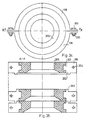
- FIG. 1 shows an embodiment of a casting tool operating with a vacuum, the closed inner cavity 3 of which delimit the shaping elements 1 lying against one another, the lower closure element 4, the upper closure element 6 and the fiber-reinforced tube 5 made of plastic.
- the tube 5 12 flanges 11 are glued with the aid of the adhesive layer.
- This on the lower flange 11 tube standing and resting on the base plate 31 becomes the load-bearing core of the plastic mold to be cast, which in this case is a high-voltage composite insulator which increases the creepage distance and is provided with plastic shields.
- the closure element 4 which is supported on the lower flange 11 and on the spacer ring 23, carries the support elements 9, which are adapted to one another by the profile grooves 10 and are connected to the closure elements 4 and 6.
- the support elements 9 and the closure elements 4 and 6 are half-rings assembled in a clamp-like manner, which are then connected by the hexagon socket screws 15 arranged in the recess 20 and screwed into the threaded holes 14 and 17.
- An opening 8 is formed in the closure element 6.
- the shaping elements 1 are provided with cuts 21, self-closing ring profiles, which are positioned by the flanges 19 of the support elements 9 and with the surfaces 2 facing each other.
- the sections 21 of the shaping elements 1 are rotated by 60 ° with respect to one another about the axis of symmetry.
- the partial surfaces 22 of the support elements 9 are arranged perpendicular to the planes of the cuts 21 of the shaping elements 1 belonging to them.
- a pouring opening is formed, to which a nozzle that introduces the pouring material is arranged.
- the O-ring 28 seals between the closure element 4 and the socket 8.
- the socket 8 is also guided through the vacuum bell 24, in the wall of which a window 25 and a socket 26 are arranged for the connection of the vacuum system.
- a vacuum seal 27 is located between the window 25 and the vacuum bell 24, a vacuum seal 29 is located between the vacuum bell 24 and the connecting piece 7, and a vacuum seal 30 is arranged between the vacuum bell 24 and the base plate 31.
- the casting material filling the inner cavity 3 protrudes from the opening 8, which can be noticed via the window 25.
- the casting material that crosslinks in the tool takes up the given shape through the shaping elements 1, the tube 5, its flanges 11 and the closure elements 4 and 6.
- the self-closing shaping elements 32 provided with cuts 33 lie against one another and are connected to one another along the surface 36.
- the shaping surface 35 of the shaping elements 32 On the side of the inner cavity 34 formed in this way is the shaping surface 35 of the shaping elements 32, while on the opposite side there are grooves 37 for the flange of the supporting elements which extends into the shaping element 32, as has already been described in the description of FIG. 1 .
- the annular shaping elements 38 provided with cuts 39 lie one on top of the other and are directed towards one another along the surface 42.
- the shaping surface 41 of the shaping elements 38 is, while on the opposite side there are grooves 43 for the flange of the support elements which extends into the shaping element, as has already been mentioned in FIG. 1.
- the continuous annular shaping elements 44 are arranged along the outer jacket of the support element 46 of a steel tube and in such a way that their surfaces 45 are directed towards one another.
- the row of shaping elements 44 is concentrically surrounded by a plastic tube 47, and between them the cavity 48 of the mold is formed. After the cavity 48 has been filled with the casting material, the plastic mold can be formed on the inner jacket of the tube.
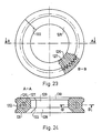
- the ring-shaped shaping element 54 contains eight cuts 49 which are formed at the same angle to one another.
- the cuts 49 divide the shaping element 54 into segments 50.
- Each segment 50 has a cylindrical shaping surface 51, a spherical shaping surface 52 and a groove 53 for the flange of the support elements which extends into the shaping element.
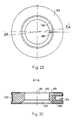
- an elastic straight profile 55 can be seen, which in the longitudinal direction has a groove 56 seen from the end plate 57 and a groove 56 seen from the opposite side.
- FIGS. 11 and 12 show a further possible embodiment of the shaping element, which is designed to be ring-shaped and bent from the straight profile 55 according to FIGS. 9 and 10.
- the straight profile 55, bent to shape, shows the contour 59 of the shaping surface of the shaping element 58 when viewed from the adapting end plate 60.
- the groove 61 for the extending flange of the support element is formed in the outer jacket of the shaping element 58.
- FIG. 13 shows a further possible embodiment of the elastic shaping element, which was designed from a straight profile with end plate 65 by spiral-like rolling up.
- the windings lying one above the other are directed towards one another along the surface 63 and enclose a cylindrically symmetrical cavity, the jacket of which forms the shaping surface 62.
- the outer surface 64 of the wound shaping element 212 forms a cylinder jacket which can expediently be supported by the inner jacket surface of a tubular support element.
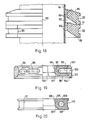
- FIGS. 14 and 15 show a further possible embodiment of the shaping element s, which is made from segments 66 of a ring profile and from parts of a straight profile.
- the sections along the lines A-A and B-B show the same profile shape, and the contour of the shaping surface 68 of the shaping element 213 and the contour of the groove 69 formed for the support element can be seen.
- the thin-walled, ring-shaped, continuous shaping element 70 is supported by means of two semi-ring-shaped clamps 73 and enclosed from the outside.
- the clamps 73 which adapt along the surface 66 are joined together by an Allen screw 78 arranged in the recess 77.
- the grooves 74 and 75 of the clamps 73 serve for the correspondingly adapted connection of the uniform support elements forming the casting tool, as has already been shown in FIG. 1.
- the shaping elements 70 arranged in series in the casting tool are directed towards one another with their surfaces 72, and the shaping surfaces 71 form a coherent tool cavity surface.
- FIG. 17 shows part of a further embodiment of the casting tool according to the invention.
- the plastic tube 87 and the thick-walled shaping elements 79 and 80 are shown, since the other components of the casting tool e.g. the supporting elements protruding into the grooves 85 correspond to the embodiment according to FIG. 1.
- the ring-shaped shaping elements of the tool shown in FIG. 17, provided with cuts 86 are produced in two ways: the surfaces 81 of the shaping elements 79 delimit a cavity part of a protruding screen, but the surfaces 82 of the shaping elements 80 delimit a cavity part of a less widely outstanding umbrella.
- the mutually adjoining shaping elements 78 and 80 which are mutually adjoining by the surfaces 84, form with the tube 87 a cavity which enables the casting of so-called plastic irolators with changing shields.
- FIG. 18 shows part of a further embodiment of the casting tool according to the invention in a simplified form, as was also shown in FIG. 17.
- the row of shaping elements 88 arranged concentrically around the plastic tube 94 forms a mold cavity in which the shaping surfaces 89 are formed in such a way that plastic insulators with an undercut shield could be cast therein.
- the ring-shaped shaping elements 88 are thick-walled and solid, they are provided with cuts 93 and a groove 92 for the support element.
- the cuts 93 of the adjacent shaping elements 88 adjoining the surfaces 91 are made rotated relative to one another about the axis of symmetry.
- FIG. 19 shows a further embodiment of the shaping element and the associated support element.
- Cavities 99 which are open to the outside through the bores 102 of the support element 101, deepen in the annular shaping element 95 from the support element 101.
- the shaping element 95 has a cut 100, a cylindrical shaping surface 96, a spherical shaping surface 97 and a surface 98 through which the shaping element connects to the adjacent shaping element in the casting tool.
- the grooves 103 and 104 of the support element 101 serve to connect and align the shaping element with the support elements of the adjacent shaping element.
- a closed cavity 109 is formed in the section of the annular shaping element 105.
- the shaping element provided with the cut 111 has a cylindrical shaping surface 106, a spherical shaping surface 107 and a surface 108 through which shaping elements arranged in series adjoin one another.
- the groove 110 which is formed in the outer jacket of the shaping element, serves as a determination groove for the flange projecting into the shaping element 105.
- FIG. 21 shows yet another embodiment of the shaping element according to the invention.
- the shaping element formed with cuts 118 has a cylindrical shaping surface 113, a spherical shaping surface 114 and a surface 115 through which the shaping element connects to the adjacent element in the casting tool.
- the groove 119 formed in the outer jacket of the shaping element 112 serves as a determining groove for the flange of the support element which projects into the shaping element.
- the ring-shaped shaping element is made of a solid material and provided with cuts 125.
- the spherical shaping surface 122 is bounded on one side with the cylindrical shaping surface 121, on the other side with the surface 123, through which adjoins a neighboring element in the tool.
- the groove 124 formed in the outer jacket of the shaping element serves as a determining groove for the flange of the support element which projects into the shaping element.
- the ring-shaped shaping element 126 is a spring insert 126 made of metal, which is also ring-shaped and is interrupted in the plane of the section 133 of the shaping element.
- the cylindrical shaping surface 129 of the shaping element 126 is delimited on one side by the spherical shaping surface 130 and on the other side by the also spherical surface 128.
- the shaping element 126 adjoins the adjacent element of the casting tool through the surface 131.
- In the outer shell of the shaping element 126 is a groove for the alignment of the support element.
- the cut annular elastic forming member 134 has one in one a flexible inner core 135.
- the cylindrical shaping surface 137 of the shaping element 134 is delimited on one side by the spherical shaping surface, on the other side by the spherical shaping surface 138.
- the shaping element 134 adjoins the adjacent element in the tool through the surface 139.
- a groove 140 is in the outer jacket of the shaping element 134.
- the cut annular shaping element is provided with a durable form-separating coating 142.
- the cylindrical shaping surface 144 of the shaping element 141 is delimited on one side by the spherical shaping surface, on the other side by the spherical shaping surface 145.
- the shaping element 141 adjoins the adjacent element of the tool through the surface 146.
- a groove 147 is formed in the outer jacket of the shaping element 141.
- Figures 27 and 28 show yet another embodiment of the shaping element.
- the ring-shaped shaping element 148 made of electrically insulating material is enclosed with an electrically conductive coating 149 on almost the entire surface, the shaping surfaces 150, 151 and 152, but with the exception of the surface of the cut 155 and the immediate vicinity of its edges, and with the exception of surface 153 and the immediate vicinity covered its edges.
- the electrically conductive coating 149 is in contact with the electrical connection elements 156, 157, and the groove 154 of the shaping element provided with an electrically conductive coating from the outer jacket side 148 protrude symmetrically arranged on both sides of the cut 155.
- the surface of the annular shaping element 158 made of electrically conductive material is provided with an insulating coating 159, the surfaces and the immediate vicinity of the edges of the cut 165 being enclosed, with the exception, however, of the shaping surfaces 160, 161, 162.
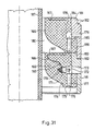
- FIG. 31 shows part of a further embodiment of the casting tool in axial section.
- two elements can be seen in the figure, in such a way that they are supported laterally on the outer lateral surfaces with supporting elements 181 and are arranged concentrically with a plastic tube 187.
- the shaping elements 166 are arranged with their surfaces 175 sealed to one another, while the shaping surface 174 and the outer jacket of the tube 187 enclose the tool cavity.
- the shaping elements 166 and the lateral surfaces 184, 186 of the support elements 181 are moderately spherical. In the intermediate parts, the adjustment is done with the help of shoulders.
- the flange 183 of the support element 181 also fits moderately spherically into the groove 182 of the adjacent support element.
- a groove 176 deepens into the surface 175 of the shaping element 166, which extends through the bore 177 with the open cavity 178 and through the bore 179 of the support element with the outer space communicates.
- the opening 173 of the support elements 181 is made for extensible electrical connection elements. This is because, in the shaping element 166, a resistance heating wire insert is placed, which is connected to the bearings 169 with electrical lines 168, and the bearings 169 are fastened with nuts 170 to the electrical plugs 172 installed in the block.
- FIG. 32 shows a further embodiment of the casting tool.
- the rigid, housing-like support element 188 provided with a cylindrical cross-section, ring-shaped shaping elements 189 are arranged one after the other with the connection surfaces 192 closing to one another.
- the shaping surfaces 190, 191 delimit the cavity 210 of the tool.
- annular, matching, mutually supporting elements 193 form a tubular, rigid housing, in which annular shaping elements are also arranged in a row, which are directed towards one another with the surfaces 197.
- the shaping surfaces 195 and 196 delimit the cavity 211 of the tool.
- Each shaping element arranged in a row is enclosed by support elements consisting of clamps 198, the flange 201 of which protrudes into the shaping element 205.
- the clamps 198 are fastened to one another by the screws 109 and nuts 200 through the bores 204.
- the edges 202 of the clamps 198 always fit into the grooves of the adjacent clamps.
- Each inner flange support member 206 has a pin that fits into the bore 207 of the adjacent support member.
- plastic castings can also be produced from a reactive casting material that are strongly structured and whose surface is provided with undercuts.
- the application of the invention is particularly economical in the production of castings, which contains a large number of identical, periodically repeating shaping elements, in particular in small production series.
- Such applications are e.g. the high-current high-voltage insulators, which are provided with plastic shields to increase the creepage distance.
Landscapes
- Engineering & Computer Science (AREA)
- Mechanical Engineering (AREA)
- Moulds For Moulding Plastics Or The Like (AREA)
- Casting Or Compression Moulding Of Plastics Or The Like (AREA)
- Polyoxymethylene Polymers And Polymers With Carbon-To-Carbon Bonds (AREA)
- Compositions Of Macromolecular Compounds (AREA)
Abstract
Description
- Die Erfindung betrifft ein Giesswerkzeug zur Herstellung von Kunststoffgussteilen und genauer ein Giesswerkzeug, das aus in Reihe angeordneten formgebenden Elementen zusammengebaut ist. Die formgebenden Elemente sind mit aneinander anschließenden Flächen versehen. Die Reihe der formgebenden Elemente bildet einen einzigen geschlossenen Hohlraum und ist an mindestens einem ihrer Enden mit einem den inneren Hohlraum absczließenden Verschlußelement versehen. Zu dem inneren Hohlraum ist auf der Seite des Giesswerkzeuges ein Anschlußstutzen für die Zuführung des Gußmaterials ausgebildet und auf der gegenüberliegenden Seite ist eine Öffnung ausgebildet.
- Die zum Giessen von Kunststoffformen dienenden Industriewerkzeuge werden aus starrem Material, mindestens aus Metall, durch kostspielige Verfahren hergestellt. Besonders teuer sind die Werkzeuge für Gusse, die stark gegliederte Flächen haben, die oft an mehreren Stellen auch verteilt sind, und aus mosaikartig aneinanderpassenden formgebenden Elementen bestehen, einerseits wegen der Zerlegbarkeit, andererseits wegen der lokalen Vetilationsmöglichkeit. Diese zwei Forderungen stehen mit der dritten Forderung, einen gratlosen Guß herzustellen, im Widerspruch. Es kommt oft vor, daß der einreißende Grat die betriebsartig nicht getrennten, zur Ventilation dienenden Spalte verstopft, und demzufolge ein Guß mit Luftblasen oder Einschlüssen entsteht.
- Eine weitentwickelte Ausführung der Giesswerkzeuge für Kunststoffe ist in der Anmeldung Nr. 28933-86 beschrieben, die ein Verfahren und eine Einrichtung beschreibt. Aus der Beschreibung ist zu lesen, daß zum Gießen von Hochspannungsisolatoren aus Kompositkunststoff ein axial verteiltes Stahlwerkzeug verwendet wird. Da die Masse und die Fläche des formgebenden Hohlraums bei diesem Werkzeug groß sind, ist es unvermeidlich, eine Schließ- und Öffnungsvorrichtung zu verwenden.
- Solche kostspieligen Werkzeuge sind nur bei Serienprodukten wirtschaftlich.
- Die Nachteile der bekannten aus starrem Material hergestellten Giesswerkzeuge sind die folgenden:
- einstückig gegossene Kunststoffformen mit untergeschnittenem Schirmsystem können nicht hergestellt werden;
- ein auf dem inneren Mantel eines Rohrens angeordnetes und damit einstückig gegossenes Kunststoffschirmsystem kann auch nicht hergestellt werden;
- zur Herstellung von mit stark gegliederten Flächen gebildeten Kunststoffgusse, deren Form nicht zylindersymmetrisch ist, kann man nur sehr teuere Werkzeuge verwenden. - Außer den obenerwähnten, aus starrem Material hergestellten Werkzeuge, sind auch Giesswerkzeuge für Kunststoffe aus elastischem Material bekannt. Auf dem Gebiet der Archäologie, des Denkmalschutzes oder Modellbildung sind seit langer Zeit Werkzeuge aus Silikongummi bekannt, wo verschiedene Reliefs oder Statuenteile in Silikonkautschuk eingebettet und dann gegossen sind. Ein solches Verfahren ist von der Firma Wacker-Chemie GmbH unter dem Titel "Elastische Formen aus RTV-2 Silikonkautschuk für Industrie", oder in der Ausgabe der Firma Rhone Poulenc Specialités Chimiques "Reproduction with a flexible silicone Mould" beschrieben. Diese Veröffentlichungen schreiben aber nichts von Werkzeugen, die aus in Reihe geschalteten formgebenden Elementen bestehen. Die bekannten Abzugsfertigungsverfahren können aber in der Industrie wegen der begrenzten Genauigkeit der Gummiwerkzeuge und wegen der komplizierten Werkzeugherstellung und wegen der Schwierigkeiten der Anpassung und Formung der Verteilungsfläche, die zur Öffnung unerläßlich sind, nicht angewandt werden. Ein Modell, dessen Größe bei großen Produkten mit dem Original gleich sein soll, zu erzeugen, macht auch an sich Probleme bzw. hat irreal große Kosten.
- Die Erfindung hat daher die Aufgabe, daß in der Einleitung beschriebene Werkzeug wirtschaftlicher zu machen und die erwähnten Nachteile zu beseitigen.
- Die Aufgabe wurde erfindungsgemäß derart gelöst, daß die formgebenden Elemente mindestens teilweise aus einem elastischen Material bestehen, des weiteren die elastischen formgebenden Elemente mit von außen umgebenden Stützelementen versehen sind, wobei die die einzelnen formgebenden Elemente umgebenden Stützelemente mit aneinander angepaßten Anschlußteilen versehen sind.
- Der Vorteil des derart hergestellten Giesswerkzeuges liegt darin, daß es aus billigen, serienmäßig hergestellten Elementen mit einheitlichen Massen aufgebaut ist, des weiteren die Spalte zwischen der sich zueinanderschaltenden Flächen der formgebenden Elemente als Ventile arbeiten und wirken, die die sich komprimierende Luft durchläßt, das Giessmaterial aber nicht. Dadurch kann sich keine Luftblase und kein Grat bilden. Die Stützelemente aus starrem Material sichern die Positionierung der formgebenden Elemente und die Befestigung der Form des Werkzeughohlraumes.
- Eine vorteilhafte Ausführungsform der Erfindung ist derart gebildet, daß das formgebende Element aus einem in sich selbst schließenden Profil besteht, und daß das in sich selbst schließende Profil ringförmig ist.
- Der Vorteil ieses Gieswerkzeuges liegt darin, daß es keinen Rand hat, wo Dichtungen vorgesehen werden sollten. Wenn das in sich selbst schließende formgebende Element gegebenenfalls geschnitten ist, kann es bei der Schnittfläche wieder ohne Spalt angepaßt werden.
- Die aufeinander angeordneten formgebenden Elemente bilden einen Werkzeughohlraum mit automatisch geschlossener Mantelfläche.
- Eine weitere vorteilhafte Ausführungsform der Erfindung ist derweise ausgebildet, daß das in sich selbst schließende Profil kontinuierlich ist.
- Der Vorteil dieser Ausführungsform liegt darin, daß die fläche des Gusses zur glatten kontinuierlichen Fläche des formgebenden Elementes ähnlich, auch glatt wird. Ein weiterer Vorteil dieser Ausführungsform liegt noch darin, daß mit deren Anwendung ein Gußstück aus Kunststoff mit großer Flächengliederung auf der inneren Mantelfläche eines rohrartigen Trägers gebildet werden kann, die an sonsten mit einem starren Werkzeug unmöglich ist.
- Bei einer weiteren vorteilhaften Ausführungsform der Erfindung ist das in sich selbst schließende Profil an mindestens einer Stelle aufgeschnitten.
- Der Vorteil dieser Ausführungsform liegt in der leichten Öffnung des Werkzeuges, da nach der Entfernung der Stützelemente die formgebenden Elementeausgehend von der Schnittstelle - ohne besondere Kraft stufenweise von der Kunststoffformfläche abtrennbar sind.
- Bei einer weiteren Ausführungsformen der Erfindung ist das in sich selbst schliessende Profil aus einem geraden Profil durch Biegen auf Form ausgebildet.
- Der Vorteil dieser Ausführungsform liegt darin, dass das Material des formgebenden Elementes durch eine kontinuierliche Technologie - durch Extrusion - hergestellt werden kann, und aus dem derweise hergestellten geraden Profil mit dessen Zergliederung formgebende Elemente mit verschiedener Form und Masse gefertigt werden können, d.h. die Abmessungen des Kunststoffgusses zwischen weiten Grenzen gewählt werden können.
- Bei einer weiteren Ausführungsform der Erfindung ist das elastische formgebende Element aus einem spiralförmig aufgewickelten geraden Profil ausgebildet.
- Der Vorteil dieser Ausführungsform liegt darin, dass der Werkzeughohlraum entlang seiner ganzen Länge den gleichen Querschnitt hat, demzufolge strömt das Giessmaterial gleichmässig, und schiebt immer die Luft vor sich her. In diesem Fall bilden sich also keine Luftblasen.
- Bei einer weiteren Ausführungsform der Erfindung ist das elastische formgebende Element durch eine Kombination von Segmenten ringförmiger Profile und gera der Profilstücke ausgebildet.
- Der Vorteil dieses Giesswerkzeuges liegt darin, dass mit dessen Hilfe ein Kunststoffguss mit Schirmfläche ohne Kontinuitätsfehler auf einer äusseren Mantelfälche eines zylinderartigen Trägers hergestellt werden kann. In dem dünnwandigen formgebenden Profil braucht kein Schnitt ausgebildet zu werden, da es auch ohne Schnitte von dem Guss abtrennbar ist, und dann durch Dehnen und Ziehen entfernt werden kann.
- Eine weitere Ausführungsform der Erfindung ist derweise gebildet, dass das in sich selbst schliessende kontinuierliche Profil dünnwandig ist.
- Bei einer weiteren Ausführungsform ist das Profil dickwandig. Der Vorteil dieser Ausführungsform liegt darin, dass zu diesem Giesswerkzeug ein Stützelement mit einfacher Form gefertigt werden kann, während das Stützelement bei dem dünnwandigen Profil als Profilfolger gebildet ist.
- Bei einer weiteren Ausführungsform der Erfindung ist das dickwandige Profil dicht (massiv). Der Vorteil dieses Giesswerkzeuges liegt darin, dass mit dessen Verwendung auch Gusse mit einem Schirm mit wesentlichem Unterschnitt hergestellt werden können. Die gute Wärmeisolierfähigkeit der formgebenden Elemente kann ausgenutzt werden, die bei Giessmaterialen, die auf die Wirkung der Wärme vernetzt werden günstig sein kann, besonders dann, wenn das Werkzeug auf der dem Stützelement gegeüberliegenden Seite geheizt wird.
- Bei einer weiteren Ausführungsform des erfindungsmässigen Werkzeuges ist das dickwandige Profil hohlräumig. Der Vorteil dieses Giesswerkzeuges liegt darin, dass in den Hohlräume heisse Luft eingeführt werden kann, und damit das Werkzeug geheizt werden kann. Zu diesem Zweck sind die Hohlräume an der Seite der Stützelemente geöffnet, und dazu müssen die Stützelemente perforiert werden.
- Bei einer weiteren Ausführungsform des erfindungsmässigen Werkzeuges ist der Hohlraum des dickwandigen Profils ein geschlossener Hohlraum. Der Vorteil dieser Ausführungsform leigt darin, dass das formgebende Element die Wärmedilatation des den Werkzeughohlraum füllenden Giessmaterilas nach der Vernetzung kompensieren kann, so tritt kein gefährlicher Überdruck auf. Ausser der obenerwähnten ergibt sich bei formgebenden Elementen, die durch Formbiegung von extrudierten Profilelementen mit Hohlräumen hergestellt sind, in dem formgebenden Element einen Positionierungsdorn anzuordnen.
- Bei einer weiteren Ausführungsform des erfindungsmässigen Werkzeuges ist der geschlossene Hohlraum mit mindestens einem Rohranschluss an den Aussenraum versehen. Der Vorteil dieses Giesswerkzeuges liegt darin, dass das formgebende Element mit Heiz- und/oder Kühlmedium gefüllt werden kann bzw. von einem solchen Medium durchströmt werden kann.
- Bei einer weiteren Ausführungsform besteht das formgebende Element aus einem einzigen Material. Der Vorteil dieser Ausführungsform liegt in ihrer Billigkeit, da die formgebenden Elemente derweise in einem einzigen Herstellungsschritt hergestellt werden können.
- Bei einer weiteren Ausführungsform besteht das formgebende Element aus mindestens zwei verschiedenen Materialen. Der Vorteil dieses Giesswerkzeuges liegt darin, dass die Eigenschaften, die mechanische-, elektrische- und Grenzflächenkarakteristiken des formgebenden Elementes in weiten Grenzen gewählt werden können, und die Eigenschaften der einzelnen Materialkomponen ten miteinander kombiniert werden können. In das formgebende Elemente kann sogar eine Feder aus Stahl eingebaut werden.
- Bei einer weiteren Ausführungsform des erfindungsmässigen Werkzeuges weist das formgebende Element einen biegsamen inneren Kern auf. Der Vorteil dieses Giesswerkzeuges liegt darin, dass die elastische Deformationsfähigkeit der formgebenden Elemente kleiner gewählt werden kann als sie ohne den inneren Kern sich ergebe. Die Biegsamkeit kann aber sogar erhöht werden. Bei einer solchen Ausbildung kann das formgebende Element sogar als sich plastisches deformierbares Element gebildet werden.
- Bei einer weiteren Ausführungsform der Erfindung, ist auf der Oberfläche des formgebenden Elementes ein beständiger formtrennender Überzug ausgebildet. Der Vorteil dieses Giesswerkzeuges liegt darin, dass die Haftung und die Adhäsion zwischen der formgebenden Oberfläche des Werkzeuges und der Oberfläche der ausgegossenen Kunststoffform vermindert werden kann. Die Abtrennung der formgebenden Elemente erleichtert sich, und vermindert sich die Verletzungsgefahr der gegossenen Schirme mit dünnem Rand.
- Bei einer weiteren Ausführungsform besteht das formgebende Element aus einem elektrisch isolierenden Material, wobei das elektrisch isolierende Material mit einem elektrisch leitenden Überzug versehen ist. Der Vorteil dieses Giesswerkzeuges liegt darin, dass es elektrisch geheizt werden kann. Der Strom wird über den elektrisch leitenden Überzug geführt, und demzufolge erwärmt sich die Oberfläche der einzelnen formgebenden Elemente. Den einen Teil der auftretenden Wärmemenge kann das Giessmaterial unmittelbar aufnehmen, womit dessen Vernetzung beschleunigt werden kann.
- Gemäss einer weiteren Ausführungsform besteht das formgebende Element aus einem elektrisch leitenden Material, wobei das elektrisch leitende Material mit einem elektrisch isolierenden Überzug versehen ist. Der Vorteil dieses Giesswerkzeuges liegt darin, dass es elektrisch geheizt werden kann, und der Heizstrom der einzelnen formgebenden Elemente kann von einer Stromquelle von kleiner Spannung geführt werden, da der elektrische Widerstand der in ihrem gesamten Querschnitt leitenden formgebenden Elemente für entsprechend klein gewählt werden kann.
- Gemäss einer weiteren vorteilhaften Ausführungsform ist in dem Querschnitt des formgebenden Elementes eine Widerstandsheizdrahteinlage angeordnet. Der Vorteil dieses Werkzeuges liegt darin, dass es elektrisch geheizt werden kann, und zwar so, daß das den Hohlraum des Giesswerkzeuges füllende Giessmaterial mit dem Heizelement nicht unmittelbar in Berührung gelangt, da das Heizelement in das formgebende Element, zweckmässig unter dessen Oberfläche, eingebettet ist. Dadurch kann man vermeiden,z.B. die Oberfläche der gegossenen Kunststoffform mit einem leitfähigen Material zu verunreinigen.
- Noch eine weitere Ausführungsform der Erfindung ist derart ausgebildet, dass die Gesamtheit der formgebenden Elemente von aussen als Stützelement von einem steifen Gehäuse umgeben ist, oder von innen von einem steifen Gehäuse abgestützt ist. Der Vorteil dieses Giesswerkzeuges liegt darin, dass es liecht ausführbar, und relativ billig herstellbar ist.
- Bei einer weiteren Ausführungsform weist das steife Gehäuse einen zylindrischen Querschnitt auf. Der Vorteil dieses Giesswerkzeuges liegt darin, dass es mit einer einfachen Technologie herstellbar ist, desweite ren die Positionierung des Stützelementes bezüglich der weiteren Elemente des Werkzeuges genau einstellbar ist.
- Noch eine weitere Ausführungsform ist der art geformt, dass das zylindrischen Querschnitt aufweisende steife Gehäuse aus Ringen gebildet ist. Der Vorteil dieses Giesswerkzeuges liegt darin, dass es einfach montiert werden kann, da die formgebenden Elemente als Stützelementringe an ihre Stellen angeordnet, bzw. von dort entfernt werden können. Ein weiterer Vorteil ist die gesicherte zylindersymmetrische Form der Stützelement-Ringe.
- Gemäss einer weiteren Ausführungsform sind die Stützelemente der formgebenden Elemente aus zwei Hälften bestehenden Schellen. Der Vorteil dieses Giesswerkzeuges liegt darin, dass durch Verbindung der formgebenden Elemente mit Schellen, die Gratbildung entlang dem Profilschnitt auch dann verhindert werden kann, wenn das formgebende Element aus einem geraden Profil durch Formbiegung gefertigt wurde.
- Bei einer weiteren vorteilhaften Ausführungsform sind die einander angepassten Anschlussteile der Stützelemente Profilnuten. Der Vorteil dieses Giesswerkzeuges liegt darin, dass die Ausrichtung der Reihe der formgebenden Elemente auch bei langen zylindersymmetrischen Werkzeughohlräumen relativ leicht sichergestellt den kann.
- Gemäss einem weiteren Ausführungsform sind die aneinander angepassten Anschlussteile der Stützelemente verzapfte Hohlräume. Der Vorteil dieses Giesswerkzeuges liegt darin, dass reproduzierbarer Werkzeughohlraum sichergestellt auch dann, wenn die Form der Elemente von einer zylindersymmetrischen Form abweicht.
- Das erfindungsgemässe Werkzeug dient zur Herstellung von Hochspannungsisolatoren, die mit Kunststoffschirmen zur Verlängerung der Krichstrecke versehen sind.
- Im weiteren wird die Erfindung mit Hilfe von Ausführungsbeispielen in den beigelegten Zeichnungen näher erläutert.
- Fig. 1 zeigt eine mögliche Ausführungsform der Erfindung in einem Halbschnitt,
- Fig. 2 zeigt die Reihe der elastischen formgebenden Elemente in einer möglichen Ausführungsform in einer Untersicht,
- Fig. 3 zeigt den Schnitt entlang der Linie A-A der Fig. 2,
- Fig. 4 zeigt eine weitere Ausführungsform der Reihe der elastischen formgebenden Elemente in einer Untersicht,
- Fig. 5 zeigt den Schnitt entlang der Linie A-A der Fig. 4,
- Fig. 6 zeigt einen Teil einer weiteren Ausführungsform des Giesswerkzeuges in Halbsicht und in dem Schnitt durch die Achse,
- Fig. 7 zeigt eine weitere Ausführungsform des elastischen formgebenden Elementes in einer Untersicht,
- Fig. 8 zeigt einen Schnitt der Fig. 7 entlang der Linie A-A,
- Fig. 9 die Ansicht des elastischen geraden Profils von der Endplatte her, wobei dieses Profil bei Herstellung einer weiteren Ausführung des formgebenden Elementes verwendet wird,
- Fig. 10 zeigt die Ansicht der in Fig. 9 gezeigten geraden Profils von der Seite der formgebenden Oberfläche her,
- Fig. 11 zeigt eine weitere Ausführungsform des formgebenden Elementes in Untersicht,
- Fig. 12 den Schnitt entlang der Linie A-A der Fig. 11, wobei die Hälfte der Figur einen Halbschnitt zeigt,
- Fig. 13 zeigt eine weitere Ausführungsform des formgebenden Elementes in perspektivischer Ansicht,
- Fig. 14 zeigt eine weitere Ausführungsform des formgebenden Elementes in Draufsicht,
- Fig. 15 zeigt den Schnitt entlang der Linien A-A und B-B der Fig. 14,
- Fig. 16 zeigt eine mögliche Ausführungsform des formgebenden Elementes und des zugehörigen Stützelementes in einem Halbschritt,
- Fig. 17 zeigt einen Teil einer weiteren Ausführung des erfindungsmässigen Giesswerkzeuges ohne Stützelemente, in einem Halbschnitt,
- Fig. 18 zeigt einen Teil einer weiteren Ausführung des Giesswerkzeuges ohne Stützelemente, in einem Halbschnitt
- Fig. 19 zeigt eine weitere Ausführungsform des elastischen formgebenden Elementes und des zugehörigen Stützelementes in einem Halbschnitt,
- Fig. 20 zeigt eine weitere Ausführungsform des elastischen formgebenden Elementes in einem Halbschnitt,
- Fig. 21 zeigt eine weitere Ausführungsform des elastischen formgebenden Elementes in einem Halbschnitt,
- Fig. 22 zeigt eine weitere Ausführungsform des elastischen formgebenden Elementes in einemHalbschnitt,
- Fig. 23 zeigt eine weitere Ausführungsform des formgebenden Elementes in Untersicht und den Ausbruch entlang der Linie B-B der Fig. 24 im Schnitt,
- Fig. 24 zeigt den Schnitt entlang der Linie A-A der Fig. 23,
- Fig. 25 zeigt eine weitere Ausführungsform des formge benden Elementes im Axialschnitt,
- Fig. 26 zeigt eine weitere Ausführungsform des formgebenden Elementes im Axialschnitt,
- Fig. 27 zeigt eine weitere Ausführungsform des formgebenden Elementes in einer Untersicht,
- Fig. 28 zeigt den Schnitt entlang der Linie A-A der Fig. 27,
- Fig. 29 zeigt eine weitere mögliche Ausführungsform des formgebenden Elementes in einer Untersicht
- Fig. 30 zeigt den Schnitt entlang der Linie A-A der Fig. 29,
- Fig. 31 zeigt einen Teil der weiteren Ausführungsform des Giesswerkzeuges in einem Halbschnitt
- Fig. 32 zeigt eine weitere Ausführungsform der Stützelemente und der mit Ihnen gestützten Reihe der formgebender Elemente im Axialschnitt,
- Fig. 33 eine weitere Ausführungsform der Stützelemente und der durch die Stützelementen gestützten Reihe von formgebeneden Elementen im Axialschnitt,
- Fig. 34 zeigt noch eine weitere Ausführungsform der Stützelemente und der durch die Stützelemente gestützten Reihe der formgebenden Elemente in einer Untersicht,
- Fig. 35 zeigt einen Schnitt entlang der Linie A-A in Fig. 34,
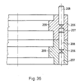
- Fig. 36 zeigt eine weitere Ausführungsform des Stützelementes im Axialschnitt,
- Fig. 1 zeigt eine Ausführungsform eines mit Vakuum arbeitenden Giesswerkzeues dessen geschlossenen inneren Hohlraum 3 die aneinander liegenden formgebenden Elemente 1, das untere Verschlusselement 4, das obere Verschlusselement 6 und das faserverstärkte Rohr 5 aus Kunststoff begrenzen. An beiden Enden des Rohres 5 sind mit Hilfe der Klebeschicht 12 Flansche 11 geklebt. Dieses auf dem unteren Flansch 11 stehende und auf der Grundplatte 31 ruhende Rohr wird der lasttragende Kern der zu giessenden Kunststoffform, die in diesem Fall ein die Kriechstrecke erhöhender mit Kunststoffschirmen versehener Hochspannungskompositisolator ist. Das sich an den unteren Flansch 11 und an den Abstandsring 23 abstützzende Verschlusselement 4 trägt die Stützelemente 9, die durch die Profilnuten 10 aufeinander angepasst und zu den Verschlusselementen 4 und 6 geschaltet sind. Die Stützelemente 9 und die Verschlusselemente 4 und 6 sind schellenartig zusammengebaute Halbringe, die dann durch die in der Ausnehmung 20 angeordneten und in die Gewindelöcher 14 und 17 geschraubten Innensechskantenschrauben 15 verbunden sind. In dem Verschlusselement 6 ist eine Öffnung 8 ausgebildet. Das Verschlußelement 6 und noch zwei weitere positionierende Bolzen 13, von denen der linksseitige in die Bohrung 16 passt. Die formgebenden Elemente 1 sind mit Schnitten 21 versehene, in sich selbst schliessende Ringprofile, die durch die Flansche 19 der Stützelemente 9 positioniert und mit den Oberflächen 2 zueinander gerichtet sind. Die Schnitte 21 der formgebenden Elemente 1 sind um die Symmetrieachse zueinander um 60° gedreht. Die Teilflächen 22 der Stützelemente 9 sind bezüglich der Ebenen der zu Ihnen gehörenden Schnitte 21 der formgebenden Elemente 1 senkrecht angeordnet. In dem Verschlusselement 4 ist eine Giessöffnung gebildet, zu der ein das Giessmaterial einführender Stutzen angeordnet ist. Der O-Ring 28 dichtet zwischen dem Verschlusselement 4 und dem Stutzen 8. Der Stutzen 8 ist auch durch die Vakuumglocke 24 geführt, in deren Wand ein Fenster 25 und ein Stutzen 26 für die Zuschaltung des Vakuumsystems angeordnet sind. Zwischen dem Fenster 25 und der Vakuumglocke 24 ist eine Vakuumabdichtung 27, zwischen der Vakuumglocke 24 und dem Stutzen 7 ist eine Vakuumabdichtung 29, und zwischen der Vakuumglocke 24 und der Grundplatte 31 ist eine Vakuumabdichtung 30 angeordnet. Während des Verfahrens wird erst die Luft aus der auf der Grundplatte 31 stehenden Vakuumglocke 24 über den Stutzen 26 entfernt, dann kann man das Werkzeug über den Stutzen 7 mit dem Giessmaterial aufgiessen.
- Das den inneren Hohlraum 3 ausfüllende Giessmaterial aus der Öffnung 8 quellt hervor, was über das Fenster 25 bemerkt werden kann. Das in dem Werkzeug sich vernetzende Gießmaterial nimmt durch die formgebenden Elemente 1, das Rohr 5, dessen Flansche 11 sowie durch die Verschlußelemente 4 und 6 die gegebene Form auf.
- Fig. 2 und 3 zeigen eine weitere mögliche Ausführungsform des elastischen formgebenden Elementes. Die in sich selbst schließenden, mit Schnitten 33 versehenen formgebenden Elemente 32 liegen aneinander, und sind entlang der Fläche 36 miteinander verbunden. Auf der Seite des derart gebildeten inneren Hohlraums 34 ist die formgebende Fläche 35 der formgebenden Elemente 32, während auf der gegenüberliegenden Seite Nuten 37 für den in das formgebende Element 32 einreichenden Flansch der Stützelemente sind, wie bei der Beschreibung der Fig. 1 schon beschrieben wurde.
- Die Fig. 4 und 5 zeigen eine weitere Ausführungsform des elastischen formgebenden Elementes. Die mit Schnitten 39 versehenen ringförmigen formgebenden Elemente 38 liegen aufeinander und sind entlang der Fläche 42 zueinander gerichtet. Auf der Seite von dem derart gebildeten inneren Hohlraums 40 her ist die formgebende Fläche 41 der ormgebenden Elemente 38 während auf der gegenüberliegenden Seite Nuten 43 für den in das formgebende Element einreichenden Flansch der Stützelemente sind, wie bei der Fig. 1 schon erwähnt wurde.
- Fig. 6 zeigt einen Teil einer weiteren möglichen Ausführungsform des erfindungsmässigen Gießwerkzeuges. Die kontinuierlichen ringförmigen formgebenden Elemente 44 sind entlang dem äußeren Mantel des Stützelementes 46 eines Stahlrohres angeordnet und zwar derart, daß sie mit ihren Flächen 45 zueinander gerichtet sind. Die Reihe der formgebenden Elemente 44 wird konzentrisch mit einem Kunststoffrohr 47 umgeben, und zwischen denen formt sich der Hohlraum 48 des Gießwerkzeuges. Nach der Auffüllung des Hohlraums 48 mit dem Gießmaterial, kann man auf dem inneren Mantel des Rohres die Kunststoffform formen.
- Fig. 7 und 8 zeigen eine weitere Ausführungsform des formgebenden Elements. Das ringförmige formgebende Element 54 beinhaltet acht Schnitte 49, die in gleichem Winkel zueinander ausgebildet sind. Die Schnitte 49 teilen das formgebende Element 54 in Segmente 50. Jedes Segment 50 hat eine zylindrische formgebende Fläche 51, eine kugelförmige formgebende Fläche 52 und eine Nut 53 für den in das formgebende Element einreichenden Flansch der Stützelemente.
- In den Fig. 9 und 10 ist ein elastisches gerades Profil 55 zu sehen, das in Längsrichtung eine Nut 56 von der Endplatte 57 her gesehen, und eine Nut 56 von der gegenüberliegenden Seite her gesehen, enthält.
- Die Fig. 11 und 12 zeigen eine weitere mögliche Ausführungsform des formgebenden Elementes, das aus dem geraden Profil 55 gemäß Fig. 9 und 10 ringförmig gebogen ausgestaltet ist. Das auf Form gebogene gerade Profil 55 zeigt von der anpassenden Endplatte 60 her gesehen die Kontur 59 der formgebenden Fläche des formgebenden Elementes 58. In dem äußeren Mantel des formgebenden Elementes 58 ist die Nut 61 für den hineinreichenden Flansch des Stützelementes ausgebildet.
- Fig. 13 zeigt eine weitere mögliche Ausführungsform des elastischen formgebenden Elementes, das aus einem geraden Profil mit Endplatte 65 durch spiralartiges Aufrollen ausgestaltet wurde. Die übereinander liegenden Windungen sind entlang der Fläche 63 zueinander gerichtet und schließen einen zylindersymmetrischen Hohlraum ein, dessen Mantel die formgebende Fläche 62 bildet. Die äußere Fläche 64 des gewickelten formgebenden Elementes 212 bildet einen Zylindermantel, der zweckmäßig durch die innere Mantelfläche eines rohrartigen Stützelements gestützt werden kann.
- Die Figuren 14 und 15 zeigen eine weitere mögliche Ausführungsform des formgebenden Element s, das aus Segmenten 66 eines Ringprofils und aus Teilen eines geraden Profils gefertigt ist. Die Schnitte entlang der Linien A-A und B-B zeigen dieselbe Profilform, und man kann die Kontur der formgebenden Fläche 68 des formgebenden Elementes 213 und die Kontur der für das Stützelement gebildeten Nut 69 sehen.
- Fig. 16 zeigt eine weitere mögliche Ausführungsform des formgebenden Elements und des dazugehörigen Stützelements. Das dünnwandige, ringförmige, kontinuierliche formgebende Element 70 wird mit Hilfe von zwei halbringförmigen Schellen 73 gestützt und von außen umschlossen. Die entlang der Fläche 66 anpassenden Schellen 73 sind mit einer in der Ausnehmung 77 angeordneten Innensechskantenschraube 78 zusammengefügt. Die Nuten 74 und 75 der Schellen 73 dienen zur entsprechend angepaßten Verbindung der das Gießwerkzeug bildenden gleichförmigen Stützelemente, wie schon in Fig. 1 gezeigt wurde. Die in dem Gießwerkzeug derart in Reihe angeordneten formgebenden Elemente 70 sind mit ihren Flächen 72 zueinander gerichtet, und die formgebenden Flächen 71 bilden eine zusammenhängende Werkzeughohlraumfläche.
- Die Fig. 17 zeigt einen Teil einer weiteren Ausführungsform des erfindungsmässigen Gießwerkzeuges. In dieser Figur ist nur die den Hohlraum 83 des Gießwerkzeuges grenzenden wichtigsten Elemente d.h. das Kunststoffrohr 87 und die dickwandigen formgebenden Elemente 79 und 80 gezeigt, da die weiteren Bauelemente des Gießwerkzeuges z.B. die in die Nuten 85 einragenden Stützelemente, mit der Ausführung gemäß Fig. 1 übereinstimmen. Die in Fig. 17 gezeigten ringförmigen mit Schnitten 86 versehenen formgebenden Elemente des Werkzeuges sind auf zweierlei Art gefertigt: Die Flächen 81 der formgebenden Elemente 79 begrenzen einen Hohlraumteil eines weit herausragenden Schirms, die Flächen 82 der formgebenden Elemente 80 begrenzen aber einen Hohlraumteil eines weniger weit herausragenden Schirmes. Die durch die Flächen 84 zueinanderschließenden wechselnd aneinander angeordneten formgebenden Elemente 78 und 80 bilden mit dem Rohr 87 einen Hohlraum, der das Gießen von sogenannten Kunststoffirolatoren mit wechselnden Schirmen ermöglicht.
- Fig. 18 zeigt einen Teil einer weiteren Ausführungsform des erfindungsmässigen Gießwerkzeuges in einer vereinfachten Form, wie es auch in Fig. 17 gezeigt wurde. Die Reihe der um das Kunststoffrohr 94 konzentrisch angeordneten formgebenden Elemente 88 bildet einen Werkzeughohlraum, in dem die formgebenden Flächen 89 derart gebildet sind, daß darin Kunststoffisolatoren mit unterschnittenem Schirm gegossen werden könnte. Die ringförmigen formgebenden Elemente 88 sind dickwandig und massiv gefertigt, sie sind mit Schnitten 93, und einer Nut 92 für das Stützelement versehen. Die Schnitte 93 der mit den Flächen 91 aneinander anschließenden benachbarten formgebenden Elemente 88 sind um die Symmetrieachse zueinander gedreht gefertigt.
- Fig. 19 zeigt eine weitere Ausführungsform des formgebenden Elementes und des dazugehörigen Stützelementes. In dem ringförmigen formgebenden Element 95 vertiefen sich von dem Stützelement 101 her Hohlräume 99, die durch die Bohrungen 102 des Stützelementes 101 nach außen geöffnet sind. Das formgebende Element 95 hat einen Schnitt 100, zylinderförmige formgebende Fläche 96, eine kugelartige formgebende Fläche 97 sowie eine Fläche 98, durch die sich das formgebende Element an das benachbarte formgebende Element in dem Gießwerkzeug anschließt. Die Nuten 103 und 104 des Stützelementes 101 dienen zu der Verbindung und Ausrichtung des formgebenden Elementes zu den Stützelementen des benachbarten formgebenden Elementes.
- Fig. 20 zeigt eine weitere Ausführungsform des formgebenden Elementes. In dem Schnitt des ringförmigen formgebenden Elementes 105 ist ein geschlossener Hohlraum 109 gebildet. Das mit dem Schnitt 111 versehene formgebende Element hat eine zylindrische formgebende Fläche 106, eine kugelartige formgebende Fläche 107 sowie eine Fläche 108, durch die in Reihe angeordnete formgebende Elemente aneinander anschließen. Die Nut 110, die in dem äußeren Mantel des formgebenden Elementes gebildet ist, dient als Bestimmungsnut für den in das formgebende Element 105 einragenden Flansch.
- Fig. 21 zeigt noch eine weitere Ausführungsform des erfindungsmäßigen formgebenden Elementes. Im Querschnitt des ringförmigen formgebenden Elementes 112 ist ein Hohlraum 116, der durch Stutzen 117 mit dem äußeren Raum in Verbindung steht. Das mit Schnitten 118 gebildete formgebende Element hat eine zylindrische formgebende Fläche 113, eine kugelartige formgebende Fläche 114 sowie eine Fläche 115, durch die sich das formgebende Element an dem benachbarten Element in dem Gießwerkzeug anschließt. Die in dem äußeren Mantel des formgebenden Elements 112 gebildete Nut 119 dient als Bestimmungsnut für den in das formgebende Element einragenden Flansch des Stützelementes.
- Fig. 22 zeigt wieder eine weitere mögliche Ausführungsform der erfindungsmäßigen formgebenden Elemente. Das ringförmige formgebende Element ist aus einem Material massiv und mit Schnitten 125 versehen gefertigt. Die kugelartige formgebende Fläche 122 ist von der einen Seite mit der zylindrischen formgebenden Fläche 121, von der anderen Seite mit der Fläche 123 begrenzt, durch die sich an ein Nachbarelement in dem Werkzeug anschließt. Die in dem äußeren Mantel des formgebenden Elementes gebildete Nut 124 dient als Bestimmungsnut für den in das formgebende Element einragenden Flansch des Stützelementes.
- Die Fig. 23 und 24 zeigen wieder eine weitere Ausführungsform des erfindungsmäßigen formgebenden Elementes. Im Querschnitt des ringförmigen formgebenden Elementes 126 ist ein Federeinsatz 126 aus Metall, der auch ringförmig ausgebildet und in der Ebene des Schnittes 133 des formgebenden Elementes unterbrochen ist. Die zylindrische formgebende Fläche 129 des formgebenden Elementes 126 wird auf der einen Seite von der kugelförmigen formgebenden Fläche 130 auf der anderen Seite von der auch kugelförmigen Fläche 128 begrenzt. Das formgebende Element 126 schließt sich durch die Fläche 131 an das benachbarte Element des Gießwerkzeuges an. In dem äußeren Mantel des formgebenden Elementes 126 ist eine Nut für die Ausrichtung des Stützelementes.
- Fig. 25 zeigt wieder eine weitere Ausführungsform des formgebenden Elementes. Das geschnittene ringförmige elastische formgebende Element 134 hat in einem Pro filquerschnitt einen biegbaren inneren Kern 135. Die zylindrische formgebende Fläche 137 des formgebenden Elementes 134 ist auf der einen Seite durch die kugelartige formgebende Fläche, auf der anderen Seite durch die auch kugelförmige formgebende Fläche 138 begrenzt. Das formgebende Element 134 schließt sich durch die Fläche 139 an das benachbarte Element in dem Werkzeug an. In dem äußeren Mantel des formgebenden Elements 134 ist eine Nut 140.
- Fig. 26 zeigt eine weitere Ausführungsform des formgebenden Elementes. Das geschnittene ringförmige formgebende Element ist mit einem beständigen formtrennenden Überzug 142 versehen. Die zylindrische formgebende Fläche 144 des formgebenden Elementes 141 ist auf der einen Seite durch die kugelförmige formgebende Fläche, auf der anderen Seite durch die auch kugelförmige formgebende Fläche 145 begrenzt. Das formgebende Element 141 schließt sich durch die Fläche 146 an das benachbarte Element des Werkzeuges an. In dem äußeren Mantel des formgebenden Elementes 141 ist eine Nut 147 gebildet.
- Die Figuren 27 und 28 zeigen noch eine weitere Ausführungsform des formgebenden Elementes. Das ringförmige, aus elektrisch isolierendem Material hergestellte formgebende Element 148 ist mit einem elektrisch leitenden Überzug 149 nahezu auf der ganzen Oberfläche, die formgebenden Flächen 150, 151 und 152 eingeschlossen, aber mit Ausnahme der Fläche des Schnittes 155, sowie der unmittelbaren Umgebung dessen Kanten, und mit der Ausnahme der Fläche 153 und der unmittelbaren Umgebung deren Kanten überzogen. Der elektrisch leitende Überzug 149 steht mit den elektrischen Anschlußelementen 156, 157 im Kontakt, die aus der äußeren mantelseitigen mit elektrisch leitendem Überzug versehenen Nut 154 des formgebenden Elements 148 auf der beiden Seite des Schnittes 155 symmetrisch angeordnet herausragen.
- Die Fig. 29 und 30 zeigen wieder eine weitere Ausführungsform des erfindungsmässigen formgebenden Elementes. Die Fläche des ringförmigen aus elektrisch leitendem Material hergestellten formgebenden Elementes 158 ist mit einem isolierenden Überzug 159, die Flächen und die unmittelbare Umgebung der Kanten des Schnittes 165 eingeschlossen mit der Ausnahme aber der formgebenden Flächen 160, 161, 162 versehen. In das formgebende Element 158 - von der Richtung der äußeren mantelseitigen Nut 163 - ragen zwei elektrische Anschlußhülsen 164 auf der beiden Seite des Schnittes 165 symmetrisch angeordnet hinein.
- Fig. 31 zeigt einen Teil einer weiteren Ausführungsform des Gießwerkzeuges im Axialschnitt. Aus den ringförmig, in Reihe angeordneten formgebenden Elementen kann man in der Figur zwei Elemente sehen, und zwar derart, daß sie seitlich der äußeren Mantelflächen mit Stützelementen 181 gestützt und mit einem Kunststoffrohr 187 konzentrisch angeordnet sind. Die formgebenden Elemente 166 sind mit ihren Flächen 175 abgedichtet zueinander angeordnet, während die formgebende Fläche 174 und der äußere Mantel des Rohres 187 den Werkzeughohlraum einschließt. Die formgebenden Elemente 166 sowie die Mantelflächen 184, 186 der Stützelemente 181 sind mässig kugelartig zueinander angepaßt. In den Zwischenteilen ist die Anpassung mit Hilfe von Schultern gelöst. Der Flansch 183 des Stützelementes 181 paßt sich auch mäßig kugelartig in die Nut 182 des benachbarten Stützelementes. In die Fläche 175 des formgebenden Elementes 166 vertieft sich eine Nut 176, die durch die Bohrung 177 mit dem offenen Hohlraum 178, und durch die Bohrung 179 des Stützelementes mit dem Außenraum in Verbindung steht. Die Öffnung 173 der Stützelemente 181 ist für streckbare elektrische Anschlußelemente gefertigt. In dem formgebenden Element 166 ist nämlich ein Widerstandsheizdrahteinsatz gelegt, der mit elektrischen Leitungen 168 zu den Lagern 169 geschaltet ist, und die Lager 169 sind mit Muttern 170 zu den in dem Block eingebauten elektrischen Steckern 172 befestigt.
- Fig. 32 zeigt eine weitere Ausführungsform des Gießwerkzeuges. In dem starren, gehäuseartigen, mit zylindrischem Querschnitt versehenen Stützelement 188 sind ringförmige formgebende Elemente 189, mit den Anschlußflächen 192 zueinander schließend nacheinander angeordnet. Die formgebenden Flächen 190, 191 begrenzen den Hohlraum 210 des Werkzeuges.
- Fig. 33 zeigt eine weitere Ausführungsform des Gießwerkzeuges. Die ringförmigen angepaßten zueinander schließenden Stützelemente 193 bilden ein rohrförmiges starres Gehäuse, in dem auch ringförmige formgebende Elemente in Reihe angeordnet sind, die mit den Flächen 197 zueinander gerichtet sind. Die formgebenden Flächen 195 und 196 begrenzen den Hohlraum 211 des Werkzeuges.
- Die Fig. 34 und 35 zeigen eine weitere Ausführungsform des Werkzeuges. Jedes in Reihe angeordnete formgebende Element ist von aus Schellen 198 bestehenden Stützelementen umschlossen, deren Flansch 201 in das formgebende Element 205 hineinragt. Die Schellen 198 sind durch die Bohrungen 204 durchgeführten Schrauben 109 und Muttern 200 aneinander befestigt. Die Kanten 202 der Schellen 198 passen immer in die Nuten der benachbarten Schellen ein.
- Fig. 36 zeigt eine Ausführungsform des Stützelementes. Jedes mit innerem Flansch versehene Stützelement 206 hat einen Stift, der in die Bohrung 207 des benachbarten Stützelementes paßt.
- Mit Hilfe des erfindungsmässigen Gießwerkzeuges können aus einem reaktiven Gußmaterial auch solche Kunststoffgusse hergestellt werden, die stark gegliedert sind und deren Fläche mit Unterschneidungen versehen ist.
- Die Anwendung der Erfindung ist besonders bei der Herstellung von Gussen, die eine Vielzahl identischer sich periodisch wiederholender formgebender Elemente beinhaltet, wirtschaftlich, insbesondere bei kleinen Produktionsserien.
- Derartige Anwendungsmöglichkeiten sind z.B. die Starkstrom-Hochspannungsisolatoren, die mit Kunststoffschirmen zur Erhöhung der Kriechstrecke versehen sind.
Claims (28)
Priority Applications (1)
| Application Number | Priority Date | Filing Date | Title |
|---|---|---|---|
| AT88117997T ATE88128T1 (de) | 1987-10-30 | 1988-10-28 | Giesswerkzeug zur herstellung von kunststoffguss. |
Applications Claiming Priority (2)
| Application Number | Priority Date | Filing Date | Title |
|---|---|---|---|
| HU488687 | 1987-10-30 | ||
| HU874886A HU209476B (en) | 1987-10-30 | 1987-10-30 | Mould-device for processing plagtic-mouldings |
Publications (3)
| Publication Number | Publication Date |
|---|---|
| EP0314160A2 true EP0314160A2 (de) | 1989-05-03 |
| EP0314160A3 EP0314160A3 (en) | 1989-12-27 |
| EP0314160B1 EP0314160B1 (de) | 1993-04-14 |
Family
ID=10969151
Family Applications (1)
| Application Number | Title | Priority Date | Filing Date |
|---|---|---|---|
| EP88117997A Expired - Lifetime EP0314160B1 (de) | 1987-10-30 | 1988-10-28 | Giesswerkzeug zur Herstellung von Kunststoffguss |
Country Status (5)
| Country | Link |
|---|---|
| EP (1) | EP0314160B1 (de) |
| AT (1) | ATE88128T1 (de) |
| CS (1) | CS708888A3 (de) |
| DE (1) | DE3880257D1 (de) |
| HU (1) | HU209476B (de) |
Cited By (7)
| Publication number | Priority date | Publication date | Assignee | Title |
|---|---|---|---|---|
| EP0414615A1 (de) * | 1989-08-25 | 1991-02-27 | Ecia - Equipements Et Composants Pour L'industrie Automobile | Schalung und ihr Herstellungsverfahren zum Erhalten von geformten Gegenständen |
| EP0435446A3 (en) * | 1989-12-26 | 1992-04-15 | Cullom Machine Tool & Die, Inc. | Corrugated mold block |
| ES2056726A2 (es) * | 1992-10-23 | 1994-10-01 | Canarias Union Electrica | Perfeccionamientos en los elementos aislantes de instalaciones de alta tension. |
| WO1995006552A3 (en) * | 1993-09-03 | 1995-06-08 | Raychem Corp | Molding methods, track resistant silicone elastomer compositions and improved molded parts with better arcing, flashover and pollution resistance |
| US5695841A (en) * | 1993-09-03 | 1997-12-09 | Raychem Corporation | Molding methods, track resistant silicone elastomer compositions, and improved molded parts with better arcing, flashover, and pollution resistance |
| GB2479708A (en) * | 2010-03-02 | 2011-10-26 | Paul Colburn Jackson | Wafer mould construction |
| WO2022129340A1 (de) * | 2020-12-17 | 2022-06-23 | Fraunhofer-Gesellschaft zur Förderung der angewandten Forschung e.V. | Formanordnung und verfahren zum erzeugen eines bauteils |
Family Cites Families (4)
| Publication number | Priority date | Publication date | Assignee | Title |
|---|---|---|---|---|
| DE1629668A1 (de) * | 1966-03-03 | 1971-04-08 | Myrenne Karl Dieter | Herstellung gegossener Kunststoff-Platten |
| DE1778305A1 (de) * | 1968-04-18 | 1971-07-29 | Krauss Maffei Ag | Verfahren und Vorrichtung zum Giessen mit Dauerformen |
| DE2300128A1 (de) * | 1973-01-03 | 1974-07-25 | Ludwig Frohmueller | Verfahren und deren vorrichtungen zur herstellung von kunststoffteilen |
| DE2327108A1 (de) * | 1973-05-28 | 1974-12-19 | Ciba Geigy Ag | Vorrichtung zur herstellung eines formkoerpers mit gleichsinnig hinterschnittenen ringwuelsten je konstanten profils |
-
1987
- 1987-10-30 HU HU874886A patent/HU209476B/hu unknown
-
1988
- 1988-10-26 CS CS887088A patent/CS708888A3/cs unknown
- 1988-10-28 DE DE8888117997T patent/DE3880257D1/de not_active Expired - Lifetime
- 1988-10-28 EP EP88117997A patent/EP0314160B1/de not_active Expired - Lifetime
- 1988-10-28 AT AT88117997T patent/ATE88128T1/de not_active IP Right Cessation
Cited By (10)
| Publication number | Priority date | Publication date | Assignee | Title |
|---|---|---|---|---|
| EP0414615A1 (de) * | 1989-08-25 | 1991-02-27 | Ecia - Equipements Et Composants Pour L'industrie Automobile | Schalung und ihr Herstellungsverfahren zum Erhalten von geformten Gegenständen |
| FR2651170A1 (fr) * | 1989-08-25 | 1991-03-01 | Ecia Equip Composants Ind Auto | Moule et son procede de fabrication pour l'obtention de pieces moulees. |
| EP0435446A3 (en) * | 1989-12-26 | 1992-04-15 | Cullom Machine Tool & Die, Inc. | Corrugated mold block |
| ES2056726A2 (es) * | 1992-10-23 | 1994-10-01 | Canarias Union Electrica | Perfeccionamientos en los elementos aislantes de instalaciones de alta tension. |
| WO1995006552A3 (en) * | 1993-09-03 | 1995-06-08 | Raychem Corp | Molding methods, track resistant silicone elastomer compositions and improved molded parts with better arcing, flashover and pollution resistance |
| US5695841A (en) * | 1993-09-03 | 1997-12-09 | Raychem Corporation | Molding methods, track resistant silicone elastomer compositions, and improved molded parts with better arcing, flashover, and pollution resistance |
| AU686663B2 (en) * | 1993-09-03 | 1998-02-12 | Raychem Corporation | Molding methods, track resistant silicone elastomer compositions and improved molded parts with better arcing, flashover and pollution resistance |
| US5830405A (en) * | 1993-09-03 | 1998-11-03 | Raychem Corporation | Molding methods, track resistant silicone elastomer compositions and improved molded parts with better arcing, flashover and pollution resistance |
| GB2479708A (en) * | 2010-03-02 | 2011-10-26 | Paul Colburn Jackson | Wafer mould construction |
| WO2022129340A1 (de) * | 2020-12-17 | 2022-06-23 | Fraunhofer-Gesellschaft zur Förderung der angewandten Forschung e.V. | Formanordnung und verfahren zum erzeugen eines bauteils |
Also Published As
| Publication number | Publication date |
|---|---|
| DE3880257D1 (de) | 1993-05-19 |
| EP0314160A3 (en) | 1989-12-27 |
| CS708888A3 (en) | 1992-01-15 |
| HUT51188A (en) | 1990-04-28 |
| HU209476B (en) | 1994-06-28 |
| ATE88128T1 (de) | 1993-04-15 |
| EP0314160B1 (de) | 1993-04-14 |
Similar Documents
| Publication | Publication Date | Title |
|---|---|---|
| DE69019552T2 (de) | Verfahren zum Einsetzen eines starren Elements zur Membrantrennung, Filtration oder katalytischen Umwandlung in ein Modul. | |
| EP0064247B1 (de) | Vorrichtung zum Herstellen von Formteilen mit asphärischen Oberflächen | |
| EP0314160B1 (de) | Giesswerkzeug zur Herstellung von Kunststoffguss | |
| EP0425981B1 (de) | Heisskanalblock | |
| DE2111763C3 (de) | Verfahren und Vorrichtung zum Herstellen eines Kanalmantels einer Profildüse zum Strangpressen von plastischen Stoffen, insbesondere von Kunststoffen | |
| DE19611213A1 (de) | Pressformvorrichtung zur Herstellung von Verbundisolatoren | |
| DE19741081C1 (de) | Verfahren zum Herstellen einer Antennenlinse | |
| WO1998006556A1 (de) | Spritzgiessform und verfahren zum herstellen von hohlkörpern | |
| EP0224702B1 (de) | Kunststoff-Formstoff mit angeformten oder eingeformten gummielastischen Teilen | |
| EP0279904B1 (de) | Rohrförmig ausgebildeter Keramikkörper | |
| DE2804645A1 (de) | Rohrkupplung | |
| EP1204516B1 (de) | Verfahren zur herstellung eines hohlkörpers in schmelzkerntechnik | |
| DE3921631C2 (de) | ||
| DE7430530U (de) | Formwerkzeug zum Herstellen einer elektrischen Leiterverbindungsvorrichtung | |
| EP0145012B1 (de) | Wassereinlauf | |
| DE3445186C2 (de) | Wassereinlauf | |
| DE19944513C1 (de) | Verfahren zur Herstellung eines Hochspannungsisolators, Hochspannungsisolator sowie Vorrichtung zur Durchführung eines solchen Verfahrens | |
| DE3621653A1 (de) | Isolator fuer elektrische leitungen und verfahren zu seiner herstellung | |
| DE3918092C2 (de) | Rührwerksmühle | |
| DE3818672C2 (de) | ||
| DE2723579A1 (de) | Vorrichtung zum formen von kanalisationsschaechten | |
| EP1232050B1 (de) | Kernausschmelzverfahren zur herstellung einer hohlraumstruktur | |
| EP1004124B1 (de) | Belüftungsventil | |
| CH660643A5 (de) | Verfahren zur herstellung eines giessharz-isolators mit kapazitiven feldsteuereinlagen. | |
| DE2119952A1 (de) | Freiluft-Hochspannungs-Hängeisolator |
Legal Events
| Date | Code | Title | Description |
|---|---|---|---|
| PUAI | Public reference made under article 153(3) epc to a published international application that has entered the european phase |
Free format text: ORIGINAL CODE: 0009012 |
|
| AK | Designated contracting states |
Kind code of ref document: A2 Designated state(s): AT BE CH DE ES FR GB GR IT LI LU NL SE |
|
| PUAL | Search report despatched |
Free format text: ORIGINAL CODE: 0009013 |
|
| AK | Designated contracting states |
Kind code of ref document: A3 Designated state(s): AT BE CH DE ES FR GB GR IT LI LU NL SE |
|
| 17P | Request for examination filed |
Effective date: 19900518 |
|
| 17Q | First examination report despatched |
Effective date: 19910718 |
|
| RAP1 | Party data changed (applicant data changed or rights of an application transferred) |
Owner name: FURUKAWA ELECTRIC TECHNOLOGIAI INTEZET KFT. |
|
| GRAA | (expected) grant |
Free format text: ORIGINAL CODE: 0009210 |
|
| AK | Designated contracting states |
Kind code of ref document: B1 Designated state(s): AT BE CH DE ES FR GB GR IT LI LU NL SE |
|
| PG25 | Lapsed in a contracting state [announced via postgrant information from national office to epo] |
Ref country code: IT Free format text: LAPSE BECAUSE OF FAILURE TO SUBMIT A TRANSLATION OF THE DESCRIPTION OR TO PAY THE FEE WITHIN THE PRE;WARNING: LAPSES OF ITALIAN PATENTS WITH EFFECTIVE DATE BEFORE 2007 MAY HAVE OCCURRED AT ANY TIME BEFORE 2007. THE CORRECT EFFECTIVE DATE MAY BE DIFFERENT FROM THE ONE RECORDED.SCRIBED TIME-LIMIT Effective date: 19930414 Ref country code: GB Effective date: 19930414 Ref country code: GR Free format text: LAPSE BECAUSE OF FAILURE TO SUBMIT A TRANSLATION OF THE DESCRIPTION OR TO PAY THE FEE WITHIN THE PRESCRIBED TIME-LIMIT Effective date: 19930414 Ref country code: BE Effective date: 19930414 Ref country code: NL Effective date: 19930414 Ref country code: SE Effective date: 19930414 Ref country code: ES Free format text: THE PATENT HAS BEEN ANNULLED BY A DECISION OF A NATIONAL AUTHORITY Effective date: 19930414 |
|
| REF | Corresponds to: |
Ref document number: 88128 Country of ref document: AT Date of ref document: 19930415 Kind code of ref document: T |
|
| REF | Corresponds to: |
Ref document number: 3880257 Country of ref document: DE Date of ref document: 19930519 |
|
| ET | Fr: translation filed | ||
| NLV1 | Nl: lapsed or annulled due to failure to fulfill the requirements of art. 29p and 29m of the patents act | ||
| GBV | Gb: ep patent (uk) treated as always having been void in accordance with gb section 77(7)/1977 [no translation filed] |
Effective date: 19930414 |
|
| PG25 | Lapsed in a contracting state [announced via postgrant information from national office to epo] |
Ref country code: AT Effective date: 19931028 |
|
| PG25 | Lapsed in a contracting state [announced via postgrant information from national office to epo] |
Ref country code: LU Free format text: LAPSE BECAUSE OF NON-PAYMENT OF DUE FEES Effective date: 19931031 |
|
| PLBE | No opposition filed within time limit |
Free format text: ORIGINAL CODE: 0009261 |
|
| STAA | Information on the status of an ep patent application or granted ep patent |
Free format text: STATUS: NO OPPOSITION FILED WITHIN TIME LIMIT |
|
| 26N | No opposition filed | ||
| PGFP | Annual fee paid to national office [announced via postgrant information from national office to epo] |
Ref country code: DE Payment date: 20071025 Year of fee payment: 20 |
|
| PGFP | Annual fee paid to national office [announced via postgrant information from national office to epo] |
Ref country code: CH Payment date: 20071015 Year of fee payment: 20 |
|
| PGFP | Annual fee paid to national office [announced via postgrant information from national office to epo] |
Ref country code: FR Payment date: 20071016 Year of fee payment: 20 |
|
| REG | Reference to a national code |
Ref country code: CH Ref legal event code: PL |