EP0314160A2 - Appareil de coulage pour fabriquer des objets coulés en matière plastique - Google Patents
Appareil de coulage pour fabriquer des objets coulés en matière plastique Download PDFInfo
- Publication number
- EP0314160A2 EP0314160A2 EP88117997A EP88117997A EP0314160A2 EP 0314160 A2 EP0314160 A2 EP 0314160A2 EP 88117997 A EP88117997 A EP 88117997A EP 88117997 A EP88117997 A EP 88117997A EP 0314160 A2 EP0314160 A2 EP 0314160A2
- Authority
- EP
- European Patent Office
- Prior art keywords
- casting tool
- tool according
- shaping
- elements
- profile
- Prior art date
- Legal status (The legal status is an assumption and is not a legal conclusion. Google has not performed a legal analysis and makes no representation as to the accuracy of the status listed.)
- Granted
Links
Images






Classifications
-
- B—PERFORMING OPERATIONS; TRANSPORTING
- B29—WORKING OF PLASTICS; WORKING OF SUBSTANCES IN A PLASTIC STATE IN GENERAL
- B29C—SHAPING OR JOINING OF PLASTICS; SHAPING OF MATERIAL IN A PLASTIC STATE, NOT OTHERWISE PROVIDED FOR; AFTER-TREATMENT OF THE SHAPED PRODUCTS, e.g. REPAIRING
- B29C33/00—Moulds or cores; Details thereof or accessories therefor
- B29C33/44—Moulds or cores; Details thereof or accessories therefor with means for, or specially constructed to facilitate, the removal of articles, e.g. of undercut articles
-
- B—PERFORMING OPERATIONS; TRANSPORTING
- B29—WORKING OF PLASTICS; WORKING OF SUBSTANCES IN A PLASTIC STATE IN GENERAL
- B29C—SHAPING OR JOINING OF PLASTICS; SHAPING OF MATERIAL IN A PLASTIC STATE, NOT OTHERWISE PROVIDED FOR; AFTER-TREATMENT OF THE SHAPED PRODUCTS, e.g. REPAIRING
- B29C33/00—Moulds or cores; Details thereof or accessories therefor
- B29C33/005—Moulds or cores; Details thereof or accessories therefor characterised by the location of the parting line of the mould parts
-
- B—PERFORMING OPERATIONS; TRANSPORTING
- B29—WORKING OF PLASTICS; WORKING OF SUBSTANCES IN A PLASTIC STATE IN GENERAL
- B29C—SHAPING OR JOINING OF PLASTICS; SHAPING OF MATERIAL IN A PLASTIC STATE, NOT OTHERWISE PROVIDED FOR; AFTER-TREATMENT OF THE SHAPED PRODUCTS, e.g. REPAIRING
- B29C33/00—Moulds or cores; Details thereof or accessories therefor
- B29C33/30—Mounting, exchanging or centering
- B29C33/301—Modular mould systems [MMS], i.e. moulds built up by stacking mould elements, e.g. plates, blocks, rods
- B29C33/302—Assembling a large number of mould elements to constitute one cavity
-
- B—PERFORMING OPERATIONS; TRANSPORTING
- B29—WORKING OF PLASTICS; WORKING OF SUBSTANCES IN A PLASTIC STATE IN GENERAL
- B29C—SHAPING OR JOINING OF PLASTICS; SHAPING OF MATERIAL IN A PLASTIC STATE, NOT OTHERWISE PROVIDED FOR; AFTER-TREATMENT OF THE SHAPED PRODUCTS, e.g. REPAIRING
- B29C33/00—Moulds or cores; Details thereof or accessories therefor
- B29C33/44—Moulds or cores; Details thereof or accessories therefor with means for, or specially constructed to facilitate, the removal of articles, e.g. of undercut articles
- B29C33/48—Moulds or cores; Details thereof or accessories therefor with means for, or specially constructed to facilitate, the removal of articles, e.g. of undercut articles with means for collapsing or disassembling
- B29C33/50—Moulds or cores; Details thereof or accessories therefor with means for, or specially constructed to facilitate, the removal of articles, e.g. of undercut articles with means for collapsing or disassembling elastic or flexible
- B29C33/505—Moulds or cores; Details thereof or accessories therefor with means for, or specially constructed to facilitate, the removal of articles, e.g. of undercut articles with means for collapsing or disassembling elastic or flexible cores or mandrels, e.g. inflatable
-
- B—PERFORMING OPERATIONS; TRANSPORTING
- B29—WORKING OF PLASTICS; WORKING OF SUBSTANCES IN A PLASTIC STATE IN GENERAL
- B29C—SHAPING OR JOINING OF PLASTICS; SHAPING OF MATERIAL IN A PLASTIC STATE, NOT OTHERWISE PROVIDED FOR; AFTER-TREATMENT OF THE SHAPED PRODUCTS, e.g. REPAIRING
- B29C39/00—Shaping by casting, i.e. introducing the moulding material into a mould or between confining surfaces without significant moulding pressure; Apparatus therefor
- B29C39/22—Component parts, details or accessories; Auxiliary operations
- B29C39/26—Moulds or cores
- B29C39/34—Moulds or cores for undercut articles
-
- B—PERFORMING OPERATIONS; TRANSPORTING
- B29—WORKING OF PLASTICS; WORKING OF SUBSTANCES IN A PLASTIC STATE IN GENERAL
- B29L—INDEXING SCHEME ASSOCIATED WITH SUBCLASS B29C, RELATING TO PARTICULAR ARTICLES
- B29L2031/00—Other particular articles
- B29L2031/34—Electrical apparatus, e.g. sparking plugs or parts thereof
- B29L2031/3412—Insulators
Definitions
- the invention relates to a casting tool for the production of plastic castings and more precisely to a casting tool which is assembled from shaping elements arranged in a row.
- the shaping elements are provided with adjoining surfaces.
- the row of shaping elements forms a single closed cavity and is provided at least at one of its ends with a closure element which closes off the inner cavity.
- a connection piece for supplying the casting material is formed on the side of the casting tool and an opening is formed on the opposite side.
- the industrial tools used to cast plastic molds are produced from rigid material, at least from metal, using costly processes.
- the tools for castings are particularly expensive because they have strongly structured surfaces, which are often distributed in several places, and consist of form-fitting elements that fit together like a mosaic, on the one hand because they can be dismantled, and on the other hand because of the possibility of local vetilation.
- These two requirements conflict with the third requirement to produce a burrless cast. It often happens that the tearing ridge clogs the gaps that are not separated in the manner of operation and are used for ventilation, and consequently a cast with air bubbles or inclusions occurs.
- the object of the invention is therefore to make the tool described in the introduction more economical and to eliminate the disadvantages mentioned.
- the shaping elements consist at least partially of an elastic material, furthermore the elastic shaping elements are provided with support elements surrounding the outside, the support elements surrounding the individual shaping elements being provided with matched connecting parts.
- the advantage of the casting tool produced in this way lies in that it is made up of cheap, mass-produced elements with uniform masses, furthermore the gaps between the interconnecting surfaces of the shaping elements work and act as valves which allow the compressing air to pass through but not the casting material. As a result, no air bubble and no burr can form.
- the support elements made of rigid material ensure the positioning of the shaping elements and the attachment of the shape of the mold cavity.
- An advantageous embodiment of the invention is formed such that the shaping element consists of a self-closing profile and that the self-closing profile is annular.
- this casting tool has no edge where seals should be provided. If the self-closing shaping element is optionally cut, it can be adjusted again without a gap at the cut surface.
- the shaping elements arranged one on top of the other form a mold cavity with an automatically closed outer surface.
- Another advantageous embodiment of the invention is designed such that the self-closing profile is continuous.
- the advantage of this embodiment is that the surface of the casting is similar to the smooth, continuous surface of the shaping element, and is also smooth.
- Another advantage of this embodiment lies in the fact that with its application, a plastic casting with a large surface structure can be formed on the inner circumferential surface of a tubular support, which is otherwise impossible with a rigid tool.
- the self-closing profile is cut open at at least one point.
- the advantage of this embodiment lies in the easy opening of the tool, since after the support elements have been removed, the shaping elements can be gradually separated from the molded plastic surface without any special force.
- the self-closing profile is formed from a straight profile by bending to form.
- the advantage of this embodiment lies in the fact that the material of the shaping element can be produced by a continuous technology - by extrusion - and from the straight profile produced in this way, with its dissection, shaping elements with different shape and mass can be manufactured, i.e. the dimensions of the plastic casting can be chosen between wide limits.
- the elastic shaping element is formed from a spirally wound straight profile.
- the advantage of this embodiment is that the tool cavity has the same cross section along its entire length, consequently the casting material flows evenly and always pushes the air in front of it. In this case, no air bubbles form.
- the elastic shaping element is a combination of segments of annular profiles and straight of the profile pieces.
- This casting tool is that it can be used to produce a plastic casting with a screen surface without continuity errors on an outer jacket pit of a cylindrical carrier. No cut needs to be made in the thin-walled shaping profile, since it can be separated from the cast without cuts, and can then be removed by stretching and pulling.
- Another embodiment of the invention is formed in such a way that the self-closing continuous profile is thin-walled.
- the profile is thick-walled.
- the advantage of this embodiment is that a support element with a simple shape can be produced for this casting tool, while the support element is formed as a profile follower in the thin-walled profile.
- the thick-walled profile is dense (solid).
- the advantage of this casting tool is that it can also be used to produce castings with a screen with a significant undercut.
- the good heat insulation ability of the shaping elements can be exploited, which can be favorable for casting materials that are crosslinked to the effect of the heat, especially when the tool is heated on the side opposite the support element.
- the thick-walled profile is hollow.
- the advantage of this casting tool is that hot air can be introduced into the cavities and the tool can thus be heated.
- the cavities on the side of the support elements are open, and for this the support elements must be perforated.
- the cavity of the thick-walled profile is a closed cavity.
- the advantage of this embodiment lies in the fact that the shaping element can compensate for the heat dilatation of the casting material filling the mold cavity after the crosslinking, so that no dangerous excess pressure occurs.
- a positioning mandrel is to be arranged in the shaping element.
- the closed cavity is provided with at least one pipe connection to the exterior.
- the shaping element consists of a single material.
- the advantage of this embodiment lies in its cheapness, since the shaping elements can thus be produced in a single production step.
- the shaping element consists of at least two different materials.
- the advantage of this casting tool is that the properties, the mechanical, electrical and interface characteristics of the shaping element can be selected within wide limits, and the properties of the individual material components ten can be combined. A steel spring can even be built into the shaping element.
- the shaping element has a flexible inner core.
- the advantage of this casting tool is that the elastic deformability of the shaping elements can be chosen to be smaller than would result without the inner core. The flexibility can even be increased. With such a design, the shaping element can even be formed as a plastic deformable element.
- a permanent, form-separating coating is formed on the surface of the shaping element.
- the shaping element consists of an electrically insulating material, the electrically insulating material being provided with an electrically conductive coating.
- the shaping element consists of an electrically conductive material, the electrically conductive material being provided with an electrically insulating coating.
- a resistance heating wire insert is arranged in the cross section of the shaping element.
- Yet another embodiment of the invention is designed such that the entirety of the shaping elements is surrounded on the outside as a support element by a rigid housing, or is supported on the inside by a rigid housing.
- the advantage of this casting tool is that it is easy to carry out and relatively inexpensive to manufacture.
- the rigid housing has a cylindrical cross section.
- Yet another embodiment is shaped in such a way that the rigid cross-section having a rigid housing is formed from rings.
- the advantage of this casting tool is that it can be easily assembled since the shaping elements can be arranged in their place as support element rings or removed from there.
- Another advantage is the secure, cylinder-symmetrical shape of the support element rings.
- the support elements of the shaping elements are clamps consisting of two halves.
- the mutually adapted connecting parts of the support elements are profile grooves.
- the mutually adapted connecting parts of the support elements are mortised cavities.
- the tool according to the invention is used for the production of high-voltage insulators which are provided with plastic shields for extending the walking distance.
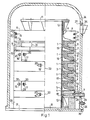
- FIG. 1 shows an embodiment of a casting tool operating with a vacuum, the closed inner cavity 3 of which delimit the shaping elements 1 lying against one another, the lower closure element 4, the upper closure element 6 and the fiber-reinforced tube 5 made of plastic.
- the tube 5 12 flanges 11 are glued with the aid of the adhesive layer.
- This on the lower flange 11 tube standing and resting on the base plate 31 becomes the load-bearing core of the plastic mold to be cast, which in this case is a high-voltage composite insulator which increases the creepage distance and is provided with plastic shields.
- the closure element 4 which is supported on the lower flange 11 and on the spacer ring 23, carries the support elements 9, which are adapted to one another by the profile grooves 10 and are connected to the closure elements 4 and 6.
- the support elements 9 and the closure elements 4 and 6 are half-rings assembled in a clamp-like manner, which are then connected by the hexagon socket screws 15 arranged in the recess 20 and screwed into the threaded holes 14 and 17.
- An opening 8 is formed in the closure element 6.
- the shaping elements 1 are provided with cuts 21, self-closing ring profiles, which are positioned by the flanges 19 of the support elements 9 and with the surfaces 2 facing each other.
- the sections 21 of the shaping elements 1 are rotated by 60 ° with respect to one another about the axis of symmetry.
- the partial surfaces 22 of the support elements 9 are arranged perpendicular to the planes of the cuts 21 of the shaping elements 1 belonging to them.
- a pouring opening is formed, to which a nozzle that introduces the pouring material is arranged.
- the O-ring 28 seals between the closure element 4 and the socket 8.
- the socket 8 is also guided through the vacuum bell 24, in the wall of which a window 25 and a socket 26 are arranged for the connection of the vacuum system.
- a vacuum seal 27 is located between the window 25 and the vacuum bell 24, a vacuum seal 29 is located between the vacuum bell 24 and the connecting piece 7, and a vacuum seal 30 is arranged between the vacuum bell 24 and the base plate 31.
- the casting material filling the inner cavity 3 protrudes from the opening 8, which can be noticed via the window 25.
- the casting material that crosslinks in the tool takes up the given shape through the shaping elements 1, the tube 5, its flanges 11 and the closure elements 4 and 6.
- the self-closing shaping elements 32 provided with cuts 33 lie against one another and are connected to one another along the surface 36.
- the shaping surface 35 of the shaping elements 32 On the side of the inner cavity 34 formed in this way is the shaping surface 35 of the shaping elements 32, while on the opposite side there are grooves 37 for the flange of the supporting elements which extends into the shaping element 32, as has already been described in the description of FIG. 1 .
- the annular shaping elements 38 provided with cuts 39 lie one on top of the other and are directed towards one another along the surface 42.
- the shaping surface 41 of the shaping elements 38 is, while on the opposite side there are grooves 43 for the flange of the support elements which extends into the shaping element, as has already been mentioned in FIG. 1.
- the continuous annular shaping elements 44 are arranged along the outer jacket of the support element 46 of a steel tube and in such a way that their surfaces 45 are directed towards one another.
- the row of shaping elements 44 is concentrically surrounded by a plastic tube 47, and between them the cavity 48 of the mold is formed. After the cavity 48 has been filled with the casting material, the plastic mold can be formed on the inner jacket of the tube.
- the ring-shaped shaping element 54 contains eight cuts 49 which are formed at the same angle to one another.
- the cuts 49 divide the shaping element 54 into segments 50.
- Each segment 50 has a cylindrical shaping surface 51, a spherical shaping surface 52 and a groove 53 for the flange of the support elements which extends into the shaping element.
- an elastic straight profile 55 can be seen, which in the longitudinal direction has a groove 56 seen from the end plate 57 and a groove 56 seen from the opposite side.
- FIGS. 11 and 12 show a further possible embodiment of the shaping element, which is designed to be ring-shaped and bent from the straight profile 55 according to FIGS. 9 and 10.
- the straight profile 55, bent to shape, shows the contour 59 of the shaping surface of the shaping element 58 when viewed from the adapting end plate 60.
- the groove 61 for the extending flange of the support element is formed in the outer jacket of the shaping element 58.
- FIG. 13 shows a further possible embodiment of the elastic shaping element, which was designed from a straight profile with end plate 65 by spiral-like rolling up.
- the windings lying one above the other are directed towards one another along the surface 63 and enclose a cylindrically symmetrical cavity, the jacket of which forms the shaping surface 62.
- the outer surface 64 of the wound shaping element 212 forms a cylinder jacket which can expediently be supported by the inner jacket surface of a tubular support element.
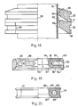
- FIGS. 14 and 15 show a further possible embodiment of the shaping element s, which is made from segments 66 of a ring profile and from parts of a straight profile.
- the sections along the lines A-A and B-B show the same profile shape, and the contour of the shaping surface 68 of the shaping element 213 and the contour of the groove 69 formed for the support element can be seen.
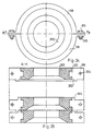
- the thin-walled, ring-shaped, continuous shaping element 70 is supported by means of two semi-ring-shaped clamps 73 and enclosed from the outside.
- the clamps 73 which adapt along the surface 66 are joined together by an Allen screw 78 arranged in the recess 77.
- the grooves 74 and 75 of the clamps 73 serve for the correspondingly adapted connection of the uniform support elements forming the casting tool, as has already been shown in FIG. 1.
- the shaping elements 70 arranged in series in the casting tool are directed towards one another with their surfaces 72, and the shaping surfaces 71 form a coherent tool cavity surface.
- FIG. 17 shows part of a further embodiment of the casting tool according to the invention.
- the plastic tube 87 and the thick-walled shaping elements 79 and 80 are shown, since the other components of the casting tool e.g. the supporting elements protruding into the grooves 85 correspond to the embodiment according to FIG. 1.
- the ring-shaped shaping elements of the tool shown in FIG. 17, provided with cuts 86 are produced in two ways: the surfaces 81 of the shaping elements 79 delimit a cavity part of a protruding screen, but the surfaces 82 of the shaping elements 80 delimit a cavity part of a less widely outstanding umbrella.
- the mutually adjoining shaping elements 78 and 80 which are mutually adjoining by the surfaces 84, form with the tube 87 a cavity which enables the casting of so-called plastic irolators with changing shields.
- FIG. 18 shows part of a further embodiment of the casting tool according to the invention in a simplified form, as was also shown in FIG. 17.
- the row of shaping elements 88 arranged concentrically around the plastic tube 94 forms a mold cavity in which the shaping surfaces 89 are formed in such a way that plastic insulators with an undercut shield could be cast therein.
- the ring-shaped shaping elements 88 are thick-walled and solid, they are provided with cuts 93 and a groove 92 for the support element.
- the cuts 93 of the adjacent shaping elements 88 adjoining the surfaces 91 are made rotated relative to one another about the axis of symmetry.
- FIG. 19 shows a further embodiment of the shaping element and the associated support element.
- Cavities 99 which are open to the outside through the bores 102 of the support element 101, deepen in the annular shaping element 95 from the support element 101.
- the shaping element 95 has a cut 100, a cylindrical shaping surface 96, a spherical shaping surface 97 and a surface 98 through which the shaping element connects to the adjacent shaping element in the casting tool.
- the grooves 103 and 104 of the support element 101 serve to connect and align the shaping element with the support elements of the adjacent shaping element.
- a closed cavity 109 is formed in the section of the annular shaping element 105.
- the shaping element provided with the cut 111 has a cylindrical shaping surface 106, a spherical shaping surface 107 and a surface 108 through which shaping elements arranged in series adjoin one another.
- the groove 110 which is formed in the outer jacket of the shaping element, serves as a determination groove for the flange projecting into the shaping element 105.
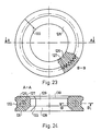
- FIG. 21 shows yet another embodiment of the shaping element according to the invention.
- the shaping element formed with cuts 118 has a cylindrical shaping surface 113, a spherical shaping surface 114 and a surface 115 through which the shaping element connects to the adjacent element in the casting tool.
- the groove 119 formed in the outer jacket of the shaping element 112 serves as a determining groove for the flange of the support element which projects into the shaping element.
- the ring-shaped shaping element is made of a solid material and provided with cuts 125.
- the spherical shaping surface 122 is bounded on one side with the cylindrical shaping surface 121, on the other side with the surface 123, through which adjoins a neighboring element in the tool.
- the groove 124 formed in the outer jacket of the shaping element serves as a determining groove for the flange of the support element which projects into the shaping element.
- the ring-shaped shaping element 126 is a spring insert 126 made of metal, which is also ring-shaped and is interrupted in the plane of the section 133 of the shaping element.
- the cylindrical shaping surface 129 of the shaping element 126 is delimited on one side by the spherical shaping surface 130 and on the other side by the also spherical surface 128.
- the shaping element 126 adjoins the adjacent element of the casting tool through the surface 131.
- In the outer shell of the shaping element 126 is a groove for the alignment of the support element.
- the cut annular elastic forming member 134 has one in one a flexible inner core 135.
- the cylindrical shaping surface 137 of the shaping element 134 is delimited on one side by the spherical shaping surface, on the other side by the spherical shaping surface 138.
- the shaping element 134 adjoins the adjacent element in the tool through the surface 139.
- a groove 140 is in the outer jacket of the shaping element 134.
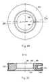
- the cut annular shaping element is provided with a durable form-separating coating 142.
- the cylindrical shaping surface 144 of the shaping element 141 is delimited on one side by the spherical shaping surface, on the other side by the spherical shaping surface 145.
- the shaping element 141 adjoins the adjacent element of the tool through the surface 146.
- a groove 147 is formed in the outer jacket of the shaping element 141.
- Figures 27 and 28 show yet another embodiment of the shaping element.
- the ring-shaped shaping element 148 made of electrically insulating material is enclosed with an electrically conductive coating 149 on almost the entire surface, the shaping surfaces 150, 151 and 152, but with the exception of the surface of the cut 155 and the immediate vicinity of its edges, and with the exception of surface 153 and the immediate vicinity covered its edges.
- the electrically conductive coating 149 is in contact with the electrical connection elements 156, 157, and the groove 154 of the shaping element provided with an electrically conductive coating from the outer jacket side 148 protrude symmetrically arranged on both sides of the cut 155.
- the surface of the annular shaping element 158 made of electrically conductive material is provided with an insulating coating 159, the surfaces and the immediate vicinity of the edges of the cut 165 being enclosed, with the exception, however, of the shaping surfaces 160, 161, 162.
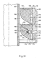
- FIG. 31 shows part of a further embodiment of the casting tool in axial section.
- two elements can be seen in the figure, in such a way that they are supported laterally on the outer lateral surfaces with supporting elements 181 and are arranged concentrically with a plastic tube 187.
- the shaping elements 166 are arranged with their surfaces 175 sealed to one another, while the shaping surface 174 and the outer jacket of the tube 187 enclose the tool cavity.
- the shaping elements 166 and the lateral surfaces 184, 186 of the support elements 181 are moderately spherical. In the intermediate parts, the adjustment is done with the help of shoulders.
- the flange 183 of the support element 181 also fits moderately spherically into the groove 182 of the adjacent support element.
- a groove 176 deepens into the surface 175 of the shaping element 166, which extends through the bore 177 with the open cavity 178 and through the bore 179 of the support element with the outer space communicates.
- the opening 173 of the support elements 181 is made for extensible electrical connection elements. This is because, in the shaping element 166, a resistance heating wire insert is placed, which is connected to the bearings 169 with electrical lines 168, and the bearings 169 are fastened with nuts 170 to the electrical plugs 172 installed in the block.
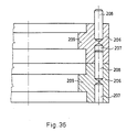
- FIG. 32 shows a further embodiment of the casting tool.
- the rigid, housing-like support element 188 provided with a cylindrical cross-section, ring-shaped shaping elements 189 are arranged one after the other with the connection surfaces 192 closing to one another.
- the shaping surfaces 190, 191 delimit the cavity 210 of the tool.
- annular, matching, mutually supporting elements 193 form a tubular, rigid housing, in which annular shaping elements are also arranged in a row, which are directed towards one another with the surfaces 197.
- the shaping surfaces 195 and 196 delimit the cavity 211 of the tool.
- Each shaping element arranged in a row is enclosed by support elements consisting of clamps 198, the flange 201 of which protrudes into the shaping element 205.
- the clamps 198 are fastened to one another by the screws 109 and nuts 200 through the bores 204.
- the edges 202 of the clamps 198 always fit into the grooves of the adjacent clamps.
- Each inner flange support member 206 has a pin that fits into the bore 207 of the adjacent support member.
- plastic castings can also be produced from a reactive casting material that are strongly structured and whose surface is provided with undercuts.
- the application of the invention is particularly economical in the production of castings, which contains a large number of identical, periodically repeating shaping elements, in particular in small production series.
- Such applications are e.g. the high-current high-voltage insulators, which are provided with plastic shields to increase the creepage distance.
Landscapes
- Engineering & Computer Science (AREA)
- Mechanical Engineering (AREA)
- Moulds For Moulding Plastics Or The Like (AREA)
- Casting Or Compression Moulding Of Plastics Or The Like (AREA)
- Polyoxymethylene Polymers And Polymers With Carbon-To-Carbon Bonds (AREA)
- Compositions Of Macromolecular Compounds (AREA)
Priority Applications (1)
| Application Number | Priority Date | Filing Date | Title |
|---|---|---|---|
| AT88117997T ATE88128T1 (de) | 1987-10-30 | 1988-10-28 | Giesswerkzeug zur herstellung von kunststoffguss. |
Applications Claiming Priority (2)
| Application Number | Priority Date | Filing Date | Title |
|---|---|---|---|
| HU488687 | 1987-10-30 | ||
| HU874886A HU209476B (en) | 1987-10-30 | 1987-10-30 | Mould-device for processing plagtic-mouldings |
Publications (3)
| Publication Number | Publication Date |
|---|---|
| EP0314160A2 true EP0314160A2 (fr) | 1989-05-03 |
| EP0314160A3 EP0314160A3 (en) | 1989-12-27 |
| EP0314160B1 EP0314160B1 (fr) | 1993-04-14 |
Family
ID=10969151
Family Applications (1)
| Application Number | Title | Priority Date | Filing Date |
|---|---|---|---|
| EP88117997A Expired - Lifetime EP0314160B1 (fr) | 1987-10-30 | 1988-10-28 | Appareil de coulage pour fabriquer des objets coulés en matière plastique |
Country Status (5)
| Country | Link |
|---|---|
| EP (1) | EP0314160B1 (fr) |
| AT (1) | ATE88128T1 (fr) |
| CS (1) | CS708888A3 (fr) |
| DE (1) | DE3880257D1 (fr) |
| HU (1) | HU209476B (fr) |
Cited By (7)
| Publication number | Priority date | Publication date | Assignee | Title |
|---|---|---|---|---|
| EP0414615A1 (fr) * | 1989-08-25 | 1991-02-27 | Ecia - Equipements Et Composants Pour L'industrie Automobile | Moule et son procÀ©dé de fabrication pour l'obtention de pièces moulées |
| EP0435446A3 (en) * | 1989-12-26 | 1992-04-15 | Cullom Machine Tool & Die, Inc. | Corrugated mold block |
| ES2056726A2 (es) * | 1992-10-23 | 1994-10-01 | Canarias Union Electrica | Perfeccionamientos en los elementos aislantes de instalaciones de alta tension. |
| WO1995006552A3 (fr) * | 1993-09-03 | 1995-06-08 | Raychem Corp | Procedes de moulage, compositions elastomeres au silicone resistantes au courant de fuite et pieces moulees ameliorees presentant une resistance superieure a la formation d'arc, au contournement et a la pollution |
| US5695841A (en) * | 1993-09-03 | 1997-12-09 | Raychem Corporation | Molding methods, track resistant silicone elastomer compositions, and improved molded parts with better arcing, flashover, and pollution resistance |
| GB2479708A (en) * | 2010-03-02 | 2011-10-26 | Paul Colburn Jackson | Wafer mould construction |
| WO2022129340A1 (fr) * | 2020-12-17 | 2022-06-23 | Fraunhofer-Gesellschaft zur Förderung der angewandten Forschung e.V. | Agencement d'éléments de moulage et procédé de fabrication d'un élément |
Family Cites Families (4)
| Publication number | Priority date | Publication date | Assignee | Title |
|---|---|---|---|---|
| DE1629668A1 (de) * | 1966-03-03 | 1971-04-08 | Myrenne Karl Dieter | Herstellung gegossener Kunststoff-Platten |
| DE1778305A1 (de) * | 1968-04-18 | 1971-07-29 | Krauss Maffei Ag | Verfahren und Vorrichtung zum Giessen mit Dauerformen |
| DE2300128A1 (de) * | 1973-01-03 | 1974-07-25 | Ludwig Frohmueller | Verfahren und deren vorrichtungen zur herstellung von kunststoffteilen |
| DE2327108A1 (de) * | 1973-05-28 | 1974-12-19 | Ciba Geigy Ag | Vorrichtung zur herstellung eines formkoerpers mit gleichsinnig hinterschnittenen ringwuelsten je konstanten profils |
-
1987
- 1987-10-30 HU HU874886A patent/HU209476B/hu unknown
-
1988
- 1988-10-26 CS CS887088A patent/CS708888A3/cs unknown
- 1988-10-28 EP EP88117997A patent/EP0314160B1/fr not_active Expired - Lifetime
- 1988-10-28 AT AT88117997T patent/ATE88128T1/de not_active IP Right Cessation
- 1988-10-28 DE DE8888117997T patent/DE3880257D1/de not_active Expired - Lifetime
Cited By (10)
| Publication number | Priority date | Publication date | Assignee | Title |
|---|---|---|---|---|
| EP0414615A1 (fr) * | 1989-08-25 | 1991-02-27 | Ecia - Equipements Et Composants Pour L'industrie Automobile | Moule et son procÀ©dé de fabrication pour l'obtention de pièces moulées |
| FR2651170A1 (fr) * | 1989-08-25 | 1991-03-01 | Ecia Equip Composants Ind Auto | Moule et son procede de fabrication pour l'obtention de pieces moulees. |
| EP0435446A3 (en) * | 1989-12-26 | 1992-04-15 | Cullom Machine Tool & Die, Inc. | Corrugated mold block |
| ES2056726A2 (es) * | 1992-10-23 | 1994-10-01 | Canarias Union Electrica | Perfeccionamientos en los elementos aislantes de instalaciones de alta tension. |
| WO1995006552A3 (fr) * | 1993-09-03 | 1995-06-08 | Raychem Corp | Procedes de moulage, compositions elastomeres au silicone resistantes au courant de fuite et pieces moulees ameliorees presentant une resistance superieure a la formation d'arc, au contournement et a la pollution |
| US5695841A (en) * | 1993-09-03 | 1997-12-09 | Raychem Corporation | Molding methods, track resistant silicone elastomer compositions, and improved molded parts with better arcing, flashover, and pollution resistance |
| AU686663B2 (en) * | 1993-09-03 | 1998-02-12 | Raychem Corporation | Molding methods, track resistant silicone elastomer compositions and improved molded parts with better arcing, flashover and pollution resistance |
| US5830405A (en) * | 1993-09-03 | 1998-11-03 | Raychem Corporation | Molding methods, track resistant silicone elastomer compositions and improved molded parts with better arcing, flashover and pollution resistance |
| GB2479708A (en) * | 2010-03-02 | 2011-10-26 | Paul Colburn Jackson | Wafer mould construction |
| WO2022129340A1 (fr) * | 2020-12-17 | 2022-06-23 | Fraunhofer-Gesellschaft zur Förderung der angewandten Forschung e.V. | Agencement d'éléments de moulage et procédé de fabrication d'un élément |
Also Published As
| Publication number | Publication date |
|---|---|
| EP0314160A3 (en) | 1989-12-27 |
| ATE88128T1 (de) | 1993-04-15 |
| CS708888A3 (en) | 1992-01-15 |
| HU209476B (en) | 1994-06-28 |
| HUT51188A (en) | 1990-04-28 |
| DE3880257D1 (de) | 1993-05-19 |
| EP0314160B1 (fr) | 1993-04-14 |
Similar Documents
| Publication | Publication Date | Title |
|---|---|---|
| DE69019552T2 (de) | Verfahren zum Einsetzen eines starren Elements zur Membrantrennung, Filtration oder katalytischen Umwandlung in ein Modul. | |
| EP0064247B1 (fr) | Dispositif pour la production d'articles moulés avec surface non-sphériques | |
| DE29522057U1 (de) | Form aus Naßgußsand zum schwerkraftunabhängigen Gießen von Nichteisenlegierungen und Formenstranganlage hierzu | |
| EP0314160B1 (fr) | Appareil de coulage pour fabriquer des objets coulés en matière plastique | |
| EP0425981B1 (fr) | Bloc à canaux de chauffe | |
| DE2111763C3 (de) | Verfahren und Vorrichtung zum Herstellen eines Kanalmantels einer Profildüse zum Strangpressen von plastischen Stoffen, insbesondere von Kunststoffen | |
| DE19611213A1 (de) | Pressformvorrichtung zur Herstellung von Verbundisolatoren | |
| DE19741081C1 (de) | Verfahren zum Herstellen einer Antennenlinse | |
| WO1998006556A1 (fr) | Moule pour injection et procede de production de corps creux | |
| EP0224702B1 (fr) | Pièce formée en plastique comportant des parties élastiques en caoutchouc insérées ou formées en surface | |
| EP0279904B1 (fr) | Corps céramique en forme de tuyau | |
| DE2804645A1 (de) | Rohrkupplung | |
| EP1204516B1 (fr) | Procede de realisation d'un corps creux par la technique de moulage a noyau fusible | |
| DE3921631C2 (fr) | ||
| DE7430530U (de) | Formwerkzeug zum Herstellen einer elektrischen Leiterverbindungsvorrichtung | |
| EP0145012B1 (fr) | Goulotte d'écoulement des eaux | |
| DE19944513C1 (de) | Verfahren zur Herstellung eines Hochspannungsisolators, Hochspannungsisolator sowie Vorrichtung zur Durchführung eines solchen Verfahrens | |
| DE3918092C2 (de) | Rührwerksmühle | |
| DE3818672C2 (fr) | ||
| DE2723579A1 (de) | Vorrichtung zum formen von kanalisationsschaechten | |
| EP1232050B1 (fr) | Procede a noyau perdu pour la production d'une structure creuse | |
| EP1004124B1 (fr) | Soupape de ventilation | |
| CH660643A5 (de) | Verfahren zur herstellung eines giessharz-isolators mit kapazitiven feldsteuereinlagen. | |
| DE2119952A1 (de) | Freiluft-Hochspannungs-Hängeisolator | |
| DE2708199A1 (de) | Verfahren zum befestigen einer muffe auf einem stab und so hergestellte verbindung |
Legal Events
| Date | Code | Title | Description |
|---|---|---|---|
| PUAI | Public reference made under article 153(3) epc to a published international application that has entered the european phase |
Free format text: ORIGINAL CODE: 0009012 |
|
| AK | Designated contracting states |
Kind code of ref document: A2 Designated state(s): AT BE CH DE ES FR GB GR IT LI LU NL SE |
|
| PUAL | Search report despatched |
Free format text: ORIGINAL CODE: 0009013 |
|
| AK | Designated contracting states |
Kind code of ref document: A3 Designated state(s): AT BE CH DE ES FR GB GR IT LI LU NL SE |
|
| 17P | Request for examination filed |
Effective date: 19900518 |
|
| 17Q | First examination report despatched |
Effective date: 19910718 |
|
| RAP1 | Party data changed (applicant data changed or rights of an application transferred) |
Owner name: FURUKAWA ELECTRIC TECHNOLOGIAI INTEZET KFT. |
|
| GRAA | (expected) grant |
Free format text: ORIGINAL CODE: 0009210 |
|
| AK | Designated contracting states |
Kind code of ref document: B1 Designated state(s): AT BE CH DE ES FR GB GR IT LI LU NL SE |
|
| PG25 | Lapsed in a contracting state [announced via postgrant information from national office to epo] |
Ref country code: IT Free format text: LAPSE BECAUSE OF FAILURE TO SUBMIT A TRANSLATION OF THE DESCRIPTION OR TO PAY THE FEE WITHIN THE PRE;WARNING: LAPSES OF ITALIAN PATENTS WITH EFFECTIVE DATE BEFORE 2007 MAY HAVE OCCURRED AT ANY TIME BEFORE 2007. THE CORRECT EFFECTIVE DATE MAY BE DIFFERENT FROM THE ONE RECORDED.SCRIBED TIME-LIMIT Effective date: 19930414 Ref country code: GB Effective date: 19930414 Ref country code: GR Free format text: LAPSE BECAUSE OF FAILURE TO SUBMIT A TRANSLATION OF THE DESCRIPTION OR TO PAY THE FEE WITHIN THE PRESCRIBED TIME-LIMIT Effective date: 19930414 Ref country code: BE Effective date: 19930414 Ref country code: NL Effective date: 19930414 Ref country code: SE Effective date: 19930414 Ref country code: ES Free format text: THE PATENT HAS BEEN ANNULLED BY A DECISION OF A NATIONAL AUTHORITY Effective date: 19930414 |
|
| REF | Corresponds to: |
Ref document number: 88128 Country of ref document: AT Date of ref document: 19930415 Kind code of ref document: T |
|
| REF | Corresponds to: |
Ref document number: 3880257 Country of ref document: DE Date of ref document: 19930519 |
|
| ET | Fr: translation filed | ||
| NLV1 | Nl: lapsed or annulled due to failure to fulfill the requirements of art. 29p and 29m of the patents act | ||
| GBV | Gb: ep patent (uk) treated as always having been void in accordance with gb section 77(7)/1977 [no translation filed] |
Effective date: 19930414 |
|
| PG25 | Lapsed in a contracting state [announced via postgrant information from national office to epo] |
Ref country code: AT Effective date: 19931028 |
|
| PG25 | Lapsed in a contracting state [announced via postgrant information from national office to epo] |
Ref country code: LU Free format text: LAPSE BECAUSE OF NON-PAYMENT OF DUE FEES Effective date: 19931031 |
|
| PLBE | No opposition filed within time limit |
Free format text: ORIGINAL CODE: 0009261 |
|
| STAA | Information on the status of an ep patent application or granted ep patent |
Free format text: STATUS: NO OPPOSITION FILED WITHIN TIME LIMIT |
|
| 26N | No opposition filed | ||
| PGFP | Annual fee paid to national office [announced via postgrant information from national office to epo] |
Ref country code: DE Payment date: 20071025 Year of fee payment: 20 |
|
| PGFP | Annual fee paid to national office [announced via postgrant information from national office to epo] |
Ref country code: CH Payment date: 20071015 Year of fee payment: 20 |
|
| PGFP | Annual fee paid to national office [announced via postgrant information from national office to epo] |
Ref country code: FR Payment date: 20071016 Year of fee payment: 20 |
|
| REG | Reference to a national code |
Ref country code: CH Ref legal event code: PL |