EP0314204A2 - Flügeltastenmechanik - Google Patents
Flügeltastenmechanik Download PDFInfo
- Publication number
- EP0314204A2 EP0314204A2 EP88201670A EP88201670A EP0314204A2 EP 0314204 A2 EP0314204 A2 EP 0314204A2 EP 88201670 A EP88201670 A EP 88201670A EP 88201670 A EP88201670 A EP 88201670A EP 0314204 A2 EP0314204 A2 EP 0314204A2
- Authority
- EP
- European Patent Office
- Prior art keywords
- lever
- distal end
- fly
- thrust
- key
- Prior art date
- Legal status (The legal status is an assumption and is not a legal conclusion. Google has not performed a legal analysis and makes no representation as to the accuracy of the status listed.)
- Ceased
Links
Images

Classifications
-
- G—PHYSICS
- G10—MUSICAL INSTRUMENTS; ACOUSTICS
- G10C—PIANOS, HARPSICHORDS, SPINETS OR SIMILAR STRINGED MUSICAL INSTRUMENTS WITH ONE OR MORE KEYBOARDS
- G10C3/00—Details or accessories
- G10C3/12—Keyboards; Keys
-
- G—PHYSICS
- G10—MUSICAL INSTRUMENTS; ACOUSTICS
- G10C—PIANOS, HARPSICHORDS, SPINETS OR SIMILAR STRINGED MUSICAL INSTRUMENTS WITH ONE OR MORE KEYBOARDS
- G10C3/00—Details or accessories
- G10C3/16—Actions
- G10C3/18—Hammers
-
- G—PHYSICS
- G10—MUSICAL INSTRUMENTS; ACOUSTICS
- G10C—PIANOS, HARPSICHORDS, SPINETS OR SIMILAR STRINGED MUSICAL INSTRUMENTS WITH ONE OR MORE KEYBOARDS
- G10C3/00—Details or accessories
- G10C3/16—Actions
- G10C3/22—Actions specially adapted for grand pianos
Definitions
- This invention relates to a mechanism for improving piano keyboard key action, especially as a part of grand or concert pianos.
- keyboard action and mechanism thereof refers to the mechanical chain of levers and combinations of levers which result in ultimately the piano key-hammer(s) striking the piano string(s) as the pianist plays on the keys. Additionally, however, it refers to the extent to which there is ease or alternately difficulty, sensitivity or alternately lack of sensitivity, to the force utilized in striking the piano key(s). It is noteworthy that the employment and use of a piano "soft pedal of a piano reflects the recognition of lack of sensitivity of key action.
- a fly lever's distal end freely passes through a space defined between forks, spaced-apart flanges in a distal end of a thrust balance lever, with the fly lever's distal end being directly in contact with and supporting solely a lower face of an abutment mounted on a lower face of an intermediate portion of a pivoted hammer shaft.
- the thrust balance lever having been pivotally mounted at an intermediate portion thereof onto the wippen lever, the blocked further upward movement of the thrust balance lever's distal end causes the proximal end of the thrust balance lever to tend to move upwardly against downwardly-biasing stress of a tension spring, with a resulting increasing build-up of stress and tension.
- the pivoted hammer shaft is thereby caused to pivotably flip-upwardly as concurrently the excessive pressure, taken together with lever action of a lower proximal end of the fly lever against an abutment mounted on the support structure, causes the fly lever's upper-end face to sidewardly pop-out from beneath the hammer-shaft abutment's lower face.
- the above-described mechanism and action results in a high degree of friction, and action involving forceably popping-out or snapping-out from its supporting position. As a result of this type of action, it is virtually impossible to effectively vary the extent of jerking-action with any appreciable degree of sensitivity.
- the "stop" that initiates the stress eventually leading to the fly lever's distal end popping-out from beneath the hammer-shaft's abutment results in greater stress as length of the fly lever employed is increased.
- Such great stress inherently is present during the key action as a result in part, of the essential long fly lever, taken together with the "stop” that prevents further upward movement of the thrust balance lever's distal end.
- the ultimate result in that type of arrangement is a lack or loss of control of sensitivity to the "touch" -- with regard to softness or loudness, when the key(s) are struck.
- objects of the invention include the avoiding and/or overcoming one or more of the problems of the types discussed above.
- Another object is to obtain an improved piano key action mechanism and operation thereof permitting sensitive and controlled execution of pianissimo and other variations of touch.
- Another object is to obtain an improved piano key action mechanism making possible the above-noted sensitivity in effecting pianissimo and other variations of touch, by a novel mechanism of improved action flexibility and diminished friction and stress and/or diminished or eliminated sudden release of stress that characterized prior key action systems.
- Another object is to obtain an improved piano key action combination achieving one or more prior objects, together with reducing friction in the operation thereof, sufficiently to avoid wear and tear associated with prior key action systems discussed above, and likewise to thereby decrease frequency of breakdowns.
- Another object is to obtain a novel key action mechanism embodying a novel combination by which pressure moving friction-causing parts away from one-another, increases as degree of key movement progresses during the stroke of a key.
- Another object is to obtain a novel key action mechanism embodying simplicity of combination and operation, together with improved and enhanced quietness thereof, while retaining essential free and fast repeating action during operation.
- Another object is to improve piano tone by virtue of improved piano key action and repeat action, with regard to speed and freedom and ease of movement, together with sensitivity of the piano key to obtain a hammer stroke by touching or striking a key.
- Another object is to obtain a novel piano key action combination eliminating or obviating dependence on the need for a soft pedal.
- Another object is to obtain a novel piano key action combination of simple manufacture and maintenance characteristics, that can be produced and maintained at low cost economically and time-wise.
- Another object is to obtain a novel piano key action combination, which by virtue of its functional achievements, makes possible a piano of fewer and smaller parts.
- the present invention is an improvement combination providing achievements and advantages never before known nor possible in any piano, particularly in grand pianos.
- the invention relates to piano key action and mechanism thereof, and more particularly for pianos as follow.
- a piano typically of conventional structure and shape having base structures for the support thereof and for the mounting of piano strings and piano keys and lever and other structure conventional for the striking of the strings of a piano.
- the structural mechanism includes, among other things, a balancing rail and a plurality of piano keys pivotally mounted thereon in the conventional fashion.
- the conventional keys each has its proximal and distal ends, with the intermediate portion thereof pivotally mounted and adapted for the distal end thereof to press and move upwardly a pivoting portion of a wippen lever of which a proximal end thereof also is mounted on the support structure, when a proximal end of the key is struck or pressed downwardly.
- Pivoted on an intermediate portion of the wippen lever is a pivotally mounted thrust balancing arm pivoted at an intermediate portion of the thrust balancing lever, with an upper face of a distal end of the thrust balancing lever being supportable of an abutment of an intermediate portion of a piano hammer's shaft.
- the piano hammer shaft also has its proximate end mounted on the support structure.
- a fly lever of which an intermediate portion thereof is mounted.
- a distal end of the fly lever extends upwardly and is supportable of the thrust balancing lever's distal end.
- a lower portion of the fly lever extends laterally or sidewardly sufficiently to eventually engage and abut an abutment member mounted on the support structure, when the distal end of the wippen lever is caused to rise as a result of striking or pressing downwardly on the key.
- the improvement includes the above structures and arrangements thereof, in a novel inventive combination with each other and other members as follow.
- the upper surface of the distal end of the thrust balancing lever directly supports and drives upwardly the hammer-shaft abutment, as the upper distal end of the fly lever contacts and upwardly drives a lower surface of the thrust balancing lever's distal end.
- the distal end of the fly lever is preferably sufficienty squared or flanged (irregularly-shaped) that when the squared portion of flange (irregularly-shaped portion) further drives upwardly, the thrust balancing lever's distal end continues upward movement (as the fly lever's distal end continues to move laterally away from its supporting position after the proximal end of the flylever has abutted the abutment as the wippenlever continued to rise as the key's proximal end is pressed further downwardly).
- an elongated resilient member extends toward and is connected to the thrust balancing lever's proximate end sufficiently that the thrust balancing lever's distal end is caused to continue to move upwardly as the fly lever's distal end moves laterally away from its supporting position; that lateral movement away is principally a result of engagement of the fly lever's proximal end with the abutment that is mounted on the support structure.
- the elongated resilient member in order to achieve optimal operation critically includes substantially non-elastic cord (or line or the like) such as preferably Nylon thread, of which a distal end thereof preferably is connected to a preferably and critically necessary (for more optimal operation and functioning) helical spring, and a proximal end thereof is connected to the wippen lever at a point spaced-away from the wippen lever's location of pivotal mounting onto the base support structure; as a result of this arrangement, as the wippen lever continues to rise after the fly lever's distal end has engaged the support-mounted abutment, the angle of resultant pressure by the resilient member on the thrust balancing lever's proximal end defines a broader angle relative to the point of mounting of the elongated resilient member's proximal end, and an equal broader angle relative to the point of mounting on a distal end of the elongated resilient member.
- substantially non-elastic cord or line or the like
- substantially non-elastic cord or
- a rigid elongated lever having its proximal end rigidly mounted on the fly lever at a point spaced-away from the pivot point of the fly lever.
- the lever extends toward the elongated resilient member, and is positioned such that lateral movement of the fly lever distal end away from its supporting position (after engagement of the fly lever's proximal end with the support-mounted abutment) causes upward movement of the rigid lever's distal end.
- the distal end of the elongated resilient member preferably the proximal end of the helical spring thereof, is caused to move concurrently immediately upwardly thereby increasing stress on the resilient member.
- the increased stretching causes the downward force on the wippen lever's proximal end to be even greater, further accentuating the upward lift and speed thereof for the wippen lever's distal end.
- the distal end of the wippen lever include a change-of-direction member, such as a roller or a spool or a pulley structure.
- the change-of-direction member is positioned and mounted such that the helical spring or preferably the non-resilient cord moves by traveling on a rolling surface of the change-of-direction member. This rolling movement further prevents or avoids frictional resistance and further provides for smooth non-jerky and easy movement of the entire key action.
- the amount of downward pressure, exerted by the helical spring and its connected typically nylon cord ring over the change-of-direction roller, is controlled by the adjustment screw located near the wippens proximal end. It can adjust the precise tension necessary to support the thrust-balancing-lever during its various functions whether at rest or in motion. Note that too much tension would cause the thrust-balancing-lever to rise and block the hammer against the string.
- spring tension from the helical spring along the longer connection from the jack to the change-of-direction roller yields during a striking action to the stronger pull on the shorter length over the change-of-direction roller and yields (expands) during a striking action to the strong pull on the anchored-shorter length (relative to the roller position) over the change-of-direction roller (running counter-clockwise) and toward the aforementioned adjustment screw.
- the tension is equalized to maintain at all times a proper balance of the thrust-balancing-lever during a multiplicity of functions.
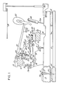
- a balance rail 11 which is supplemental support structure.
- the piano key 15 is mounted on a key balancing pin 14, with the balancing button 14a in place around the balancing pin 14.
- a supporting key-rest 12 At a distal end of the key 15, there is a supporting key-rest 12, further support structure, with the proximal end of a key which conventionally would be guided by a conventional guide pin (not shown).
- Top and bottom support structures above and below the key form aperture space 14b, aligned with the key's aperture space 15′, through which pin 14 is mounted.
- a further support member 17 (a rail), mounted on support structure 16 has mounted thereon a hammer base member (hammer shank flange) 19 on which the hammer-shaft 20 is mounted at its proximal end on pin 21, having hammer 22 at its distal end, positioned to strike string 23 when the proximal end of the key 15 is struck (played).
- An intermediate portion of the hammer-shaft 20 has the abutment 44 mounted on the underside of the hammer shaft 20.
- Shaft 24a carries the back check 24 for checking the downstrike of its related hammer 22.
- the additional support structure 18 (another rail) has mounted thereon the wippen base (flange) 29 on which pin 28 pivotally mounts wippen lever 25 having rest-member 31 by which the wippen lever 25 rests on support member 30 mounted on the key 15.
- Fly lever 26 is mounted by pin 34 on the distal end of wippen lever 25, and thrust balancing lever 27 is pivotally mounted by pin 43 on thrust balancing lever support 45 that is rigidly mounted on intermediate portion of the wippen lever 25.
- Roller 49 is mounted by pin 49′ on the proximal end of the thrust balancing lever 27.
- Elongated rigid member (rod) 51 is mounted at location 52 on and extends laterally from an intermediate portion of the fly lever 26, extending toward the roller 49, and has connected to a distal end of the fly lever 26 the distal end of helical spring 46.
- the proximal end of spring 46 is connected to the distal end of non-flexible cord 48 which is secured to screw 47 screwed into a proximal end of the wippen lever 25.
- a leather covering-pad 42 is mounted on a distal end of the thrust balancing lever 27, and also stop-member 41 is mounted on the distal end of the thrust balancing lever 27, with a padded head 39 being mounted by adjustable screw-like mount-member 38 mounted through the distal end of the fly lever 26.
- Fly lever distal end 35 has stop-abutment 36 mounted on adjustable screw-type member 37 with the stop-abutment aligned with the distal end 35 such that the fly lever distal end 35 will come into contact with and abut stop-abutment 36 when the proximal end of the piano key 15 is pressed.
- the screw-like member 37a is mounted in support rail 17a (as a further part of the additional base support structure 16, mounted thereon).
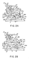
- Angle 32a is defined between the distal ends of the cord 48 and the resultant force vector 32.
- angle 32b is defined between the proximal end of cord 48 and the resultant force vector 32.
- Angle 32a is always substantially equal to angle 32b because the force exerted through opposite proximal and distal ends of the cord 48 is equal, and the resultant force vector 32 is the vector of the force on the roller 49 and its mounting pin 49′, which force or pressure is transmitted to the proximal end of the thrust balancing lever 27.
- the resultant force vector 33 results from the retraction force of helical spring 46 acting on the distal end of the lever 51.
- FIG. 2A represents the state existing prior to a pianist striking (pressing downwardly) the proximal end of the key 15, such that angles 32a′ and 32b′ are each at their smallest number of degrees.
- Figure 2B represents the state when the proximal end of the key 15 has been pressed downwardly (by the striking thereof) sufficiently for the fly lever distal end 26 c to come into contact with the stop-abutment 36 as a result of the wippen lever's distal end 25a having been lifted pivotally, together with the lifting (upward movement) of all structures mounted on the wippen lever 25.
- the number of angle degrees in each of angles 32a ⁇ and 3b ⁇ is the same as the number of degrees in each of the angles 32a′ and 32b′, because there has not been any pivoting action of the thrust balancing lever 27b thus far.
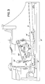
- Figure 2C illustrates the state when the proximal end of the key 15 has been further depressed (by the continuation of the striking thereof) as compared to the Figure 2B state, whereby the wippen lever has been further raised together with the mounted support 45 mounted on the wippen lever, and together with thrust balancing lever 27.
- the fly lever's 26 distal end 35 has previously abutted the stop-abutment 36, the fly lever has begun to pivot the fly lever proximal end 54 from beneath the thrust balancing lever distal end 27a (and along face 55 of leather pad 42), by which solely the squared corner 53 (of the fly lever's distal end 54) is the sole remaining frictional contact with the leather pad 42, and whereby the squared corner 53 presses upwardly an additional distance the thrust balancing lever distal end 27a, while concurrently the elongated rigid member 51 and its serially-attached helical spring 46 and the serially connected cord 48 act on the roller 49 with pressure to produce resultant force vector 32 also contributing to the lifting of the thrust balancing lever distal end 27a to the illustrated position and state.
- the Figure 2D illustrates a still further downward movement of proximal end of the key 15 in the state of maximum depression thereof, whereby the continued movement of the wippen lever 25 and the mount-structure 45 has caused the fly lever proximal end 26a and its squared flange 50 to move totally laterally (sidewardly) from supporting contact and from beneath the thrust balancing lever distal end 27a and its leather covering pad 42 as the continued lateral movement of the fly lever 26 caused the distal end of the elongated rigid lever 51 to rise upwardly as well as to move further away from the roller 49 such that even greater accentuated pulling (stretching) pressure is exerted on each of the serially connected helical springs 46 and cord 48 such that the resultant force vector 32 ⁇ is maximized in its pressure on the roller 50 thereby further depressing the thrust balancing lever proximal end 27c such that the thrust balancing lever distal end 27a is moved to its highest point; as the thrust balancing lever distal end 27a is being moved to its highest point
- the line or cord 48 may thereby be tightened, to thereby cause greater downwardly pressure on the thrust balancing lever end 27b, relieving (reducing) downward pressure of the thrust balancing lever end 27a on the squared portion (squared corner) or flange 53, such that friction would be reduced whenever the fly lever's distal end 26a begins to move laterally away from its supporting position.
- the fly lever's distal end 26a begins its lateral pivotal movement after the wippen lever 25 has moved upwardly sufficiently for the fly lever's distal end 26c to become abutted against the abutment 36, and as the wippen lever 25 thereafter continues its upward movement when the piano key's proximal end 15a ispushed further downwardly.
- the reverse adjustment effect may be achieved by loosening the screw 47 by counter-clockwise turning thereof to lessen tension on the line or cord 48.
- the scope of the invention includes having the line or cord 48 merely permanently secured solely to the thrust balancing lever end 27b such as to the post or pin 49′, such that lateral pivotal movement of fly lever end 26a outwardly (in a direction away from its supporting position of supporting thrust balancing lever end 27) immediately initiates/begins pivotally downward movement of the thrust balancing lever end 27b and the pivotal upward movement of the thrust balancing lever end 27a -- at least sufficiently to initiate reduction of pressure of the lever end 27a downwardly on the fly lever's flange 53.
- the abutment stop prevented the upper pivoting end of the fly lever (equivalent to the present fly lever distal end 26a, except that the prior art fly lever pivotal distal end directly contacted and directly supported the hammer shaft 20 or its contact abutment [equivalent to the present inventions hammer-shaft contact-abutment 44]) from being pushed indefinitely-upwardly where historically it had become jammed against the hammer shaft or its contact-abutment, and when jammed thereby prevented the normal or speedy downward movement of the hammer and its shaft after the hammer had struck the piano string.
Landscapes
- Physics & Mathematics (AREA)
- Engineering & Computer Science (AREA)
- Acoustics & Sound (AREA)
- Multimedia (AREA)
- Electrophonic Musical Instruments (AREA)
- Toys (AREA)
Applications Claiming Priority (2)
| Application Number | Priority Date | Filing Date | Title |
|---|---|---|---|
| US07/114,717 US4774868A (en) | 1987-10-30 | 1987-10-30 | Piano key action |
| US114717 | 1987-10-30 |
Publications (2)
| Publication Number | Publication Date |
|---|---|
| EP0314204A2 true EP0314204A2 (de) | 1989-05-03 |
| EP0314204A3 EP0314204A3 (de) | 1990-02-07 |
Family
ID=22357008
Family Applications (1)
| Application Number | Title | Priority Date | Filing Date |
|---|---|---|---|
| EP88201670A Ceased EP0314204A3 (de) | 1987-10-30 | 1988-08-02 | Flügeltastenmechanik |
Country Status (7)
| Country | Link |
|---|---|
| US (1) | US4774868A (de) |
| EP (1) | EP0314204A3 (de) |
| JP (1) | JPH01154094A (de) |
| KR (1) | KR900008435A (de) |
| CN (1) | CN1014749B (de) |
| CA (1) | CA1257489A (de) |
| MX (1) | MX165775B (de) |
Cited By (4)
| Publication number | Priority date | Publication date | Assignee | Title |
|---|---|---|---|---|
| DE4202994A1 (de) * | 1992-02-03 | 1993-08-05 | Karl Dewanger | Fluegel-anschlagmechanik |
| DE4414169A1 (de) * | 1994-04-22 | 1995-11-09 | Helmut Karl | Vorrichtung zur Verbesserung des Abnickverhaltens von repetierenden Flügelmechaniken |
| DE4414110A1 (de) * | 1994-04-22 | 1995-11-09 | Helmut Karl | Repetitionsmechanik für Flügel mit verminderten Störeffekten |
| AT411114B (de) * | 2000-11-27 | 2003-09-25 | Andrew Buczolits | Flügelmechanikständer |
Families Citing this family (10)
| Publication number | Priority date | Publication date | Assignee | Title |
|---|---|---|---|---|
| JP2507715Y2 (ja) * | 1988-08-29 | 1996-08-21 | 株式会社河合楽器製作所 | ピアノのアクシヨン機構 |
| DE4117453C2 (de) * | 1990-05-28 | 1997-05-15 | Yamaha Corp | Flügelmechanik mit einem Anschlagsdämpfungsmechanismus |
| RU2197753C2 (ru) * | 1998-02-19 | 2003-01-27 | Гохштейн Александр Яковлевич | Клавишный механизм рояля |
| US7687694B2 (en) * | 2007-06-14 | 2010-03-30 | Wessell, Nickel & Gross | Low inertia grand piano piano action |
| JP5298534B2 (ja) * | 2008-01-08 | 2013-09-25 | ヤマハ株式会社 | アクション機構 |
| CN102436800B (zh) * | 2011-10-20 | 2013-09-25 | 张树岩 | 键盘式拉弦器 |
| US9159302B2 (en) * | 2013-10-03 | 2015-10-13 | Steinway Musical Instruments, Inc. | Piano extended soft pedal/CIP |
| US9495940B2 (en) * | 2014-03-20 | 2016-11-15 | Casio Computer Co., Ltd. | Keyboard device and keyboard instrument |
| EP2924683B1 (de) * | 2014-03-25 | 2016-11-09 | Fazioli Pianoforti S.p.A. | Mechanische Einheit eines Klaviers |
| JP6737040B2 (ja) * | 2015-07-23 | 2020-08-05 | ヤマハ株式会社 | サポートアセンブリ及び鍵盤装置 |
Family Cites Families (5)
| Publication number | Priority date | Publication date | Assignee | Title |
|---|---|---|---|---|
| DE200582C (de) * | ||||
| DE104815C (de) * | ||||
| US2046853A (en) * | 1935-07-05 | 1936-07-07 | Sieveking Martinus | Piano-action spring |
| US2156913A (en) * | 1936-01-24 | 1939-05-02 | William S Finholm | Piano action |
| US2540871A (en) * | 1944-08-01 | 1951-02-06 | William S Finholm | Piano action |
-
1987
- 1987-10-30 US US07/114,717 patent/US4774868A/en not_active Expired - Fee Related
-
1988
- 1988-07-26 CA CA000573001A patent/CA1257489A/en not_active Expired
- 1988-08-02 EP EP88201670A patent/EP0314204A3/de not_active Ceased
- 1988-08-30 CN CN88106335A patent/CN1014749B/zh not_active Expired
- 1988-09-05 MX MX012920A patent/MX165775B/es unknown
- 1988-09-21 JP JP63235150A patent/JPH01154094A/ja active Pending
- 1988-11-18 KR KR1019880015216A patent/KR900008435A/ko not_active Withdrawn
Cited By (4)
| Publication number | Priority date | Publication date | Assignee | Title |
|---|---|---|---|---|
| DE4202994A1 (de) * | 1992-02-03 | 1993-08-05 | Karl Dewanger | Fluegel-anschlagmechanik |
| DE4414169A1 (de) * | 1994-04-22 | 1995-11-09 | Helmut Karl | Vorrichtung zur Verbesserung des Abnickverhaltens von repetierenden Flügelmechaniken |
| DE4414110A1 (de) * | 1994-04-22 | 1995-11-09 | Helmut Karl | Repetitionsmechanik für Flügel mit verminderten Störeffekten |
| AT411114B (de) * | 2000-11-27 | 2003-09-25 | Andrew Buczolits | Flügelmechanikständer |
Also Published As
| Publication number | Publication date |
|---|---|
| JPH01154094A (ja) | 1989-06-16 |
| CN1014749B (zh) | 1991-11-13 |
| EP0314204A3 (de) | 1990-02-07 |
| CN1033331A (zh) | 1989-06-07 |
| US4774868A (en) | 1988-10-04 |
| CA1257489A (en) | 1989-07-18 |
| MX165775B (es) | 1992-12-03 |
| KR900008435A (ko) | 1990-06-04 |
Similar Documents
| Publication | Publication Date | Title |
|---|---|---|
| US4774868A (en) | Piano key action | |
| JP3341438B2 (ja) | 鍵盤楽器 | |
| US5287787A (en) | Upright piano for constant key-touch regardless of manipulation of soft pedal | |
| US5610356A (en) | Keyboard musical instrument having hammer stopper exactly position at blocking position | |
| CN105684076B (zh) | 钢琴扩展的柔音踏板 | |
| US4061067A (en) | Modified piano striking mechanism | |
| KR950008538B1 (ko) | 직립피아노의 약음장치 | |
| US5583306A (en) | Keyboard musical instrument having jacks changeable in escape speed between acoustic sound mode and silent mode | |
| KR970005212B1 (ko) | 수형 피아노용 기계 장치 | |
| US8895822B2 (en) | Action for upright piano | |
| US6232537B1 (en) | Piano action with articulated jack | |
| US5511454A (en) | Piano escapement action | |
| US4381691A (en) | Touch force adjustment means for a piano | |
| KR20030077457A (ko) | 업라이트형 건반악기 | |
| US4854211A (en) | Action mechanism of an upright piano | |
| JPH0734477U (ja) | 鍵盤楽器 | |
| US7265283B2 (en) | String-striking device for piano | |
| JP2025136523A (ja) | ドロップアクションを有するピアノ | |
| US4856402A (en) | Grand piano actions | |
| JP3438741B2 (ja) | 鍵盤楽器 | |
| US2156963A (en) | Piano action | |
| US2540871A (en) | Piano action | |
| US6639133B1 (en) | Universal piano action striking vertical and horizontal strings from below and above | |
| US1490229A (en) | Grand-piano action | |
| JPH0612057A (ja) | 鍵盤楽器 |
Legal Events
| Date | Code | Title | Description |
|---|---|---|---|
| PUAI | Public reference made under article 153(3) epc to a published international application that has entered the european phase |
Free format text: ORIGINAL CODE: 0009012 |
|
| AK | Designated contracting states |
Kind code of ref document: A2 Designated state(s): DE FR GB IT LU NL SE |
|
| PUAL | Search report despatched |
Free format text: ORIGINAL CODE: 0009013 |
|
| AK | Designated contracting states |
Kind code of ref document: A3 Designated state(s): DE FR GB IT LU NL SE |
|
| 17P | Request for examination filed |
Effective date: 19900228 |
|
| 17Q | First examination report despatched |
Effective date: 19910730 |
|
| STAA | Information on the status of an ep patent application or granted ep patent |
Free format text: STATUS: THE APPLICATION HAS BEEN REFUSED |
|
| 18R | Application refused |
Effective date: 19930527 |