EP0314337B1 - Injecteur d'essence - Google Patents
Injecteur d'essence Download PDFInfo
- Publication number
- EP0314337B1 EP0314337B1 EP88309518A EP88309518A EP0314337B1 EP 0314337 B1 EP0314337 B1 EP 0314337B1 EP 88309518 A EP88309518 A EP 88309518A EP 88309518 A EP88309518 A EP 88309518A EP 0314337 B1 EP0314337 B1 EP 0314337B1
- Authority
- EP
- European Patent Office
- Prior art keywords
- valve member
- spacer
- defining
- magnetic
- injector
- Prior art date
- Legal status (The legal status is an assumption and is not a legal conclusion. Google has not performed a legal analysis and makes no representation as to the accuracy of the status listed.)
- Expired - Lifetime
Links
Images

Classifications
-
- F—MECHANICAL ENGINEERING; LIGHTING; HEATING; WEAPONS; BLASTING
- F02—COMBUSTION ENGINES; HOT-GAS OR COMBUSTION-PRODUCT ENGINE PLANTS
- F02M—SUPPLYING COMBUSTION ENGINES IN GENERAL WITH COMBUSTIBLE MIXTURES OR CONSTITUENTS THEREOF
- F02M51/00—Fuel-injection apparatus characterised by being operated electrically
- F02M51/06—Injectors peculiar thereto with means directly operating the valve needle
- F02M51/061—Injectors peculiar thereto with means directly operating the valve needle using electromagnetic operating means
- F02M51/0625—Injectors peculiar thereto with means directly operating the valve needle using electromagnetic operating means characterised by arrangement of mobile armatures
- F02M51/0635—Injectors peculiar thereto with means directly operating the valve needle using electromagnetic operating means characterised by arrangement of mobile armatures having a plate-shaped or undulated armature not entering the winding
- F02M51/0639—Injectors peculiar thereto with means directly operating the valve needle using electromagnetic operating means characterised by arrangement of mobile armatures having a plate-shaped or undulated armature not entering the winding the armature acting as a valve
-
- F—MECHANICAL ENGINEERING; LIGHTING; HEATING; WEAPONS; BLASTING
- F02—COMBUSTION ENGINES; HOT-GAS OR COMBUSTION-PRODUCT ENGINE PLANTS
- F02M—SUPPLYING COMBUSTION ENGINES IN GENERAL WITH COMBUSTIBLE MIXTURES OR CONSTITUENTS THEREOF
- F02M51/00—Fuel-injection apparatus characterised by being operated electrically
- F02M51/06—Injectors peculiar thereto with means directly operating the valve needle
- F02M51/08—Injectors peculiar thereto with means directly operating the valve needle specially for low-pressure fuel-injection
-
- F—MECHANICAL ENGINEERING; LIGHTING; HEATING; WEAPONS; BLASTING
- F02—COMBUSTION ENGINES; HOT-GAS OR COMBUSTION-PRODUCT ENGINE PLANTS
- F02M—SUPPLYING COMBUSTION ENGINES IN GENERAL WITH COMBUSTIBLE MIXTURES OR CONSTITUENTS THEREOF
- F02M2200/00—Details of fuel-injection apparatus, not otherwise provided for
- F02M2200/07—Fuel-injection apparatus having means for avoiding sticking of valve or armature, e.g. preventing hydraulic or magnetic sticking of parts
Definitions
- This invention relates to a a gasolene injector for supplying fuel to an air inlet of a spark ignition engine, the injector being of the kind comprising a central hollow magnetic core member having one end connected in use to a source of fuel, a hollow body formed from magnetic material and surrounding the core member in spaced relationship, said body defining an annular pole face which extends inwardly towards the other end of the core member, the end face of the core member defining a further pole face, a winding which in use can be energised to cause said pole faces to assume opposite magnetic polarity, a seat member spaced from said pole faces, said seat member defining an outlet orifice, a plate-like valve member formed from magnetic material located with clearance between said seat member and said pole faces and resilient means acting on said valve member to urge the valve member into contact with the seat member, said valve member being lifted from the seat member by magnetic forces when said winding is energised, to allow fuel flow through the outlet orifice.
- An injector of the aforesaid kind is known from British Patent 2147949B in which a non-magnetic spacer is provided which is positioned to prevent metal-to-metal contact of the valve member and the pole face defined by the body thereby minimizing the risk of the valve member sticking to the pole face due to residual magnetism. Whilst sticking due to magnetic effects is prevented by the spacer the valve member does tend to adhere to the spacer due to the fact that the spacer and valve member are wetted by the gasolene thereby slowing the closure of the valve member. If a stronger spring is provided to return the valve member more quickly into contact with the seat member, the magnetic force required to lift the valve member away from the seat member will be increased and as a result the power consumption of the injector will be increased.
- GB-A-2073316 shows a similar form of injector in which the contact area between the spacer member and the valve member is reduced by forming the internal peripheral surface of the spacer member with a series of circumferentially spaced cutouts which between them define tongues.
- the cutouts reduce the contact area between the spacer member and the valve member.
- the object of the present invention is to provide an injector of the aforesaid kind in a simple and convenient form.
- an injector of the kind specified comprises a non-magnetic spacer member positioned adjacent said annular pole face, said spacer member being of annular form and defining a plurality of inwardly extending circumferentially spaced tongues, whereby the contact area between the spacer member and the valve member is reduced, the inner end portions of said tongues being tapered.
- the injector comprises a hollow generally cylindrical outer body 11 formed from magnetic material within which there extends a hollow flanged core member 13 through which extends a passage 14 which connects an inlet 12 with an outlet 15 of the body.
- a former 16 Surrounding the core 13 within the body is a former 16 which is formed from synthetic resin material and upon which is wound a solenoid winding 17.
- the outlet which is in the form of a sleeve retained within the body, projects in use into an air inlet of the engine.
- the body 11 Adjacent the outlet 15 the body 11 defines an integral radially inwardly extending circumferential shoulder 18 against which a steel annulus 19 is trapped by a steel disc-like seat member 21 in which is formed an outlet orifice 22.
- the orifice extends from the surface of the valve seat member remote from the outlet and surrounding the outlet are a pair of annular seat elements 23, 23A.
- valve member 24 Located within the annulus 19 is a valve member 24 of plate-like form which is formed from magnetic material and the face of the valve member presented to the end of the core member 13 is provided with a depression in which is located one end of a coiled compression spring 26 which is housed within the passage 14.
- the internal diameter of the shoulder 18 is less than the diameter of the annulus 19 and it therefore overlies the outer peripheral portion of the valve member 24.
- the faces of the core member 13 and the shoulder 18 which are presented to the valve member define pole faces which when the winding 17 is energised, assume opposite magnetic polarity and therefore attract the valve member towards the shoulder 18 and away from the seat member 21.
- the thickness of the valve member is less than the thickness of the annulus by a predetermined amount to allow movement of the valve member and the movement of the valve member is arrested by a non-magnetic spacer member 27 which is positioned between the annulus 19 and the shoulder 18.
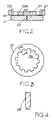
- the spacer member is formed from non-magnetic material such for example as non-magnetic stainless steel and a plan view of the spacer 27 is seen in Figure 3.
- the spacer member is of annular form and its inner peripheral surface is castellated to form a plurality of inwardly extending tongues 28 which form the portions of the spacer which are contacted by the valve member 24.
- the cutaway portions of the spacer reduce the contact area between the valve member and the spacer and thereby reduce the tendency of the valve member to stick to the spacer when the solenoid 17 is de-energised.
- the inner end portions of the tongues 28 are tapered. This is because the spacer is produced using a chemical etching process. It will be understood that the periphery of the valve member 24 engages the tongues outwardly of said inner end portions so that the fully open position of the valve member is accurately defined.
- the spacer is formed from non-magnetic stainless steel means that it will not acquire any residual magnetism during the course of use of the injector and it has been found that it cannot be contaminated by the constituents of the fuel which is supplied through the injector.
Landscapes
- Engineering & Computer Science (AREA)
- Chemical & Material Sciences (AREA)
- Combustion & Propulsion (AREA)
- Mechanical Engineering (AREA)
- General Engineering & Computer Science (AREA)
- Physics & Mathematics (AREA)
- Electromagnetism (AREA)
- Fuel-Injection Apparatus (AREA)
- Glass Compositions (AREA)
- Disintegrating Or Milling (AREA)
Claims (1)
Priority Applications (1)
| Application Number | Priority Date | Filing Date | Title |
|---|---|---|---|
| AT88309518T ATE71189T1 (de) | 1987-10-27 | 1988-10-12 | Benzineinspritzventil. |
Applications Claiming Priority (2)
| Application Number | Priority Date | Filing Date | Title |
|---|---|---|---|
| GB878725176A GB8725176D0 (en) | 1987-10-27 | 1987-10-27 | Gasolene injector |
| GB8725176 | 1987-10-27 |
Publications (2)
| Publication Number | Publication Date |
|---|---|
| EP0314337A1 EP0314337A1 (fr) | 1989-05-03 |
| EP0314337B1 true EP0314337B1 (fr) | 1992-01-02 |
Family
ID=10625986
Family Applications (1)
| Application Number | Title | Priority Date | Filing Date |
|---|---|---|---|
| EP88309518A Expired - Lifetime EP0314337B1 (fr) | 1987-10-27 | 1988-10-12 | Injecteur d'essence |
Country Status (6)
| Country | Link |
|---|---|
| US (1) | US4909447A (fr) |
| EP (1) | EP0314337B1 (fr) |
| JP (1) | JPH02146258A (fr) |
| AT (1) | ATE71189T1 (fr) |
| DE (1) | DE3867427D1 (fr) |
| GB (1) | GB8725176D0 (fr) |
Families Citing this family (21)
| Publication number | Priority date | Publication date | Assignee | Title |
|---|---|---|---|---|
| GB9217281D0 (en) * | 1992-08-14 | 1992-09-30 | Lucas Ind Plc | Fuel injector |
| US5372313A (en) * | 1993-02-16 | 1994-12-13 | Siemens Automotive L.P. | Fuel injector |
| DE69402964T2 (de) * | 1993-02-16 | 1997-10-23 | Ford Motor Co | Kraftstoffeinspritzventil |
| US5540564A (en) * | 1993-11-12 | 1996-07-30 | Stanadyne Automotive Corp. | Rotary distributor type fuel injection pump |
| US5979866A (en) * | 1995-06-06 | 1999-11-09 | Sagem, Inc. | Electromagnetically actuated disc-type valve |
| US5692723A (en) * | 1995-06-06 | 1997-12-02 | Sagem-Lucas, Inc. | Electromagnetically actuated disc-type valve |
| US6328231B1 (en) | 1998-05-27 | 2001-12-11 | Siemens Automotive Corporation | Compressed natural gas injector having improved low noise valve needle |
| US6508418B1 (en) * | 1998-05-27 | 2003-01-21 | Siemens Automotive Corporation | Contaminant tolerant compressed natural gas injector and method of directing gaseous fuel therethrough |
| US6089467A (en) * | 1999-05-26 | 2000-07-18 | Siemens Automotive Corporation | Compressed natural gas injector with gaseous damping for armature needle assembly during opening |
| US6431474B2 (en) | 1999-05-26 | 2002-08-13 | Siemens Automotive Corporation | Compressed natural gas fuel injector having magnetic pole face flux director |
| US6405947B2 (en) | 1999-08-10 | 2002-06-18 | Siemens Automotive Corporation | Gaseous fuel injector having low restriction seat for valve needle |
| US6422488B1 (en) | 1999-08-10 | 2002-07-23 | Siemens Automotive Corporation | Compressed natural gas injector having gaseous dampening for armature needle assembly during closing |
| US20040108395A1 (en) * | 2001-09-13 | 2004-06-10 | Hitachi, Ltd. | Electromagnetic fuel injector |
| US6799733B1 (en) | 2000-06-28 | 2004-10-05 | Siemens Automotive Corporation | Fuel injector having a modified seat for enhanced compressed natural gas jet mixing |
| AT412807B (de) * | 2003-06-18 | 2005-07-25 | Hoerbiger Valvetec Gmbh | Elektromagnetisch betätigtes gasventil |
| ITMI20031927A1 (it) * | 2003-10-07 | 2005-04-08 | Med S P A | Elettroiniettore perfezionato per combustibile gassoso. |
| JP4273499B2 (ja) * | 2004-07-23 | 2009-06-03 | Smc株式会社 | 電磁弁 |
| US7497203B2 (en) * | 2005-08-03 | 2009-03-03 | Caterpillar Inc. | Avoidance of spark damage on valve members |
| US8002206B2 (en) * | 2006-12-29 | 2011-08-23 | Caterpillar Inc. | Avoidance of spark damage on valve members |
| US7509948B1 (en) | 2007-10-01 | 2009-03-31 | Caterpillar Inc. | Variable displacement pump with an anti-stiction device |
| EP2138706B1 (fr) * | 2008-06-27 | 2010-11-10 | C.R.F. Società Consortile per Azioni | Injecteur de carburant doté d'une servosoupape de dosage de type équilibré pour moteur à combustion interne |
Family Cites Families (11)
| Publication number | Priority date | Publication date | Assignee | Title |
|---|---|---|---|---|
| CH492124A (de) * | 1968-06-11 | 1970-06-15 | Sopromi Soc Proc Modern Inject | Elektromagnetisch betätigtes Einspritzventil |
| DE2049671A1 (de) * | 1970-10-09 | 1972-04-13 | Bosch Gmbh Robert | Magnetventil mit Maßnahmen gegen hydraulisches Kleben |
| DE2936853A1 (de) * | 1979-09-12 | 1981-04-02 | Robert Bosch Gmbh, 7000 Stuttgart | Elektromagnetisch betaetigbares ventil |
| DE2948874A1 (de) * | 1979-12-05 | 1981-06-11 | Robert Bosch Gmbh, 7000 Stuttgart | Elektromagnetisch betaetigbares ventil |
| DE3010613A1 (de) * | 1980-03-20 | 1981-10-01 | Robert Bosch Gmbh, 7000 Stuttgart | Kraftstoffeinspritzanlage |
| DE3010612A1 (de) * | 1980-03-20 | 1981-10-01 | Robert Bosch Gmbh, 7000 Stuttgart | Elektromagnetisch betaetigbares ventil |
| EP0102723A1 (fr) * | 1982-07-29 | 1984-03-14 | LUCAS INDUSTRIES public limited company | Injecteur de carburant du type disque |
| GB8327527D0 (en) * | 1983-10-14 | 1983-11-16 | Lucas Ind Plc | Fuel injector |
| JPH0656140B2 (ja) * | 1984-12-26 | 1994-07-27 | 日本電装株式会社 | 電磁式燃料噴射弁 |
| GB8613666D0 (en) * | 1986-06-05 | 1986-07-09 | Lucas Ind Plc | Valves |
| DE3630092A1 (de) * | 1986-09-04 | 1988-03-17 | Bosch Gmbh Robert | Elektromagnetisch betaetigbares ventil |
-
1987
- 1987-10-27 GB GB878725176A patent/GB8725176D0/en active Pending
-
1988
- 1988-10-12 AT AT88309518T patent/ATE71189T1/de not_active IP Right Cessation
- 1988-10-12 EP EP88309518A patent/EP0314337B1/fr not_active Expired - Lifetime
- 1988-10-12 DE DE8888309518T patent/DE3867427D1/de not_active Expired - Lifetime
- 1988-10-17 US US07/258,421 patent/US4909447A/en not_active Expired - Fee Related
- 1988-10-26 JP JP63270614A patent/JPH02146258A/ja active Pending
Non-Patent Citations (1)
| Title |
|---|
| Werner Schatt, "Werkstoffe des Maschinen-, Anlagen- und Apparatebaues", VEB Deutscher Verlag für Grundstoffindustrie, Leipzig, 1. Auflage, 1974, Seite 407-409 * |
Also Published As
| Publication number | Publication date |
|---|---|
| US4909447A (en) | 1990-03-20 |
| ATE71189T1 (de) | 1992-01-15 |
| JPH02146258A (ja) | 1990-06-05 |
| EP0314337A1 (fr) | 1989-05-03 |
| DE3867427D1 (de) | 1992-02-13 |
| GB8725176D0 (en) | 1987-12-02 |
Similar Documents
| Publication | Publication Date | Title |
|---|---|---|
| EP0314337A1 (fr) | Injecteur d'essence | |
| EP0583139B1 (fr) | Injecteur de combustible | |
| KR100375041B1 (ko) | 인젝터의부식방지를위한셸구성요소 | |
| US4331317A (en) | Magnetic type fuel injection valve | |
| US4254935A (en) | Solenoid construction | |
| US4494701A (en) | Fuel injector | |
| GB2147949A (en) | Fuel injector for an I.C. engine | |
| EP0328277B1 (fr) | Injecteur de combustible | |
| GB2178483A (en) | Fuel injector for I.C. engines | |
| WO1988004727A1 (fr) | Injecteur de carburant | |
| EP0481608A1 (fr) | Injecteur électronique de carburant | |
| US4932593A (en) | Fuel injector | |
| DE3562290D1 (en) | Electromagnetically actuated fuel injector | |
| JPS6270655A (ja) | 電磁操作される燃料噴射弁 | |
| GB2144177A (en) | Fuel injector | |
| GB2176843A (en) | Electromagnetic valve | |
| GB2148388A (en) | Electromagnetic gasoline injector | |
| JPS60153466A (ja) | 電磁式燃料噴射弁 | |
| GB2146846A (en) | Temperature compensated solenoid device | |
| GB1599316A (en) | Electromagnetically operable fluid valve | |
| GB1586044A (en) | Electro-magnetically operable valves | |
| JP2574528Y2 (ja) | ソレノイドバルブ | |
| DE3573944D1 (en) | Electromagnetically actuated fuel injector | |
| JPS6111450A (ja) | 電磁式燃料噴射弁 | |
| US20030038263A1 (en) | Electromagnetic actuator for a fuel injector |
Legal Events
| Date | Code | Title | Description |
|---|---|---|---|
| PUAI | Public reference made under article 153(3) epc to a published international application that has entered the european phase |
Free format text: ORIGINAL CODE: 0009012 |
|
| AK | Designated contracting states |
Kind code of ref document: A1 Designated state(s): AT BE DE ES FR GB GR IT NL |
|
| 17P | Request for examination filed |
Effective date: 19891030 |
|
| 17Q | First examination report despatched |
Effective date: 19900502 |
|
| GRAA | (expected) grant |
Free format text: ORIGINAL CODE: 0009210 |
|
| AK | Designated contracting states |
Kind code of ref document: B1 Designated state(s): AT BE DE ES FR GB GR IT NL |
|
| PG25 | Lapsed in a contracting state [announced via postgrant information from national office to epo] |
Ref country code: NL Effective date: 19920102 Ref country code: GR Free format text: LAPSE BECAUSE OF FAILURE TO SUBMIT A TRANSLATION OF THE DESCRIPTION OR TO PAY THE FEE WITHIN THE PRESCRIBED TIME-LIMIT Effective date: 19920102 Ref country code: ES Free format text: THE PATENT HAS BEEN ANNULLED BY A DECISION OF A NATIONAL AUTHORITY Effective date: 19920102 Ref country code: BE Effective date: 19920102 Ref country code: AT Effective date: 19920102 |
|
| REF | Corresponds to: |
Ref document number: 71189 Country of ref document: AT Date of ref document: 19920115 Kind code of ref document: T |
|
| ITF | It: translation for a ep patent filed | ||
| REF | Corresponds to: |
Ref document number: 3867427 Country of ref document: DE Date of ref document: 19920213 |
|
| ET | Fr: translation filed | ||
| NLV1 | Nl: lapsed or annulled due to failure to fulfill the requirements of art. 29p and 29m of the patents act | ||
| PLBE | No opposition filed within time limit |
Free format text: ORIGINAL CODE: 0009261 |
|
| STAA | Information on the status of an ep patent application or granted ep patent |
Free format text: STATUS: NO OPPOSITION FILED WITHIN TIME LIMIT |
|
| 26N | No opposition filed | ||
| PGFP | Annual fee paid to national office [announced via postgrant information from national office to epo] |
Ref country code: GB Payment date: 19961003 Year of fee payment: 9 |
|
| PGFP | Annual fee paid to national office [announced via postgrant information from national office to epo] |
Ref country code: FR Payment date: 19961009 Year of fee payment: 9 |
|
| PGFP | Annual fee paid to national office [announced via postgrant information from national office to epo] |
Ref country code: DE Payment date: 19961018 Year of fee payment: 9 |
|
| PG25 | Lapsed in a contracting state [announced via postgrant information from national office to epo] |
Ref country code: GB Free format text: LAPSE BECAUSE OF NON-PAYMENT OF DUE FEES Effective date: 19971012 |
|
| PG25 | Lapsed in a contracting state [announced via postgrant information from national office to epo] |
Ref country code: FR Free format text: THE PATENT HAS BEEN ANNULLED BY A DECISION OF A NATIONAL AUTHORITY Effective date: 19971031 |
|
| GBPC | Gb: european patent ceased through non-payment of renewal fee |
Effective date: 19971012 |
|
| PG25 | Lapsed in a contracting state [announced via postgrant information from national office to epo] |
Ref country code: DE Free format text: LAPSE BECAUSE OF NON-PAYMENT OF DUE FEES Effective date: 19980701 |
|
| REG | Reference to a national code |
Ref country code: FR Ref legal event code: ST |
|
| PG25 | Lapsed in a contracting state [announced via postgrant information from national office to epo] |
Ref country code: IT Free format text: LAPSE BECAUSE OF NON-PAYMENT OF DUE FEES;WARNING: LAPSES OF ITALIAN PATENTS WITH EFFECTIVE DATE BEFORE 2007 MAY HAVE OCCURRED AT ANY TIME BEFORE 2007. THE CORRECT EFFECTIVE DATE MAY BE DIFFERENT FROM THE ONE RECORDED. Effective date: 20051012 |