EP0314668A2 - Commande hydraulique - Google Patents
Commande hydraulique Download PDFInfo
- Publication number
- EP0314668A2 EP0314668A2 EP88890270A EP88890270A EP0314668A2 EP 0314668 A2 EP0314668 A2 EP 0314668A2 EP 88890270 A EP88890270 A EP 88890270A EP 88890270 A EP88890270 A EP 88890270A EP 0314668 A2 EP0314668 A2 EP 0314668A2
- Authority
- EP
- European Patent Office
- Prior art keywords
- cylinder
- piston rod
- piston
- space
- line
- Prior art date
- Legal status (The legal status is an assumption and is not a legal conclusion. Google has not performed a legal analysis and makes no representation as to the accuracy of the status listed.)
- Granted
Links
Images

Classifications
-
- A—HUMAN NECESSITIES
- A61—MEDICAL OR VETERINARY SCIENCE; HYGIENE
- A61F—FILTERS IMPLANTABLE INTO BLOOD VESSELS; PROSTHESES; DEVICES PROVIDING PATENCY TO, OR PREVENTING COLLAPSING OF, TUBULAR STRUCTURES OF THE BODY, e.g. STENTS; ORTHOPAEDIC, NURSING OR CONTRACEPTIVE DEVICES; FOMENTATION; TREATMENT OR PROTECTION OF EYES OR EARS; BANDAGES, DRESSINGS OR ABSORBENT PADS; FIRST-AID KITS
- A61F2/00—Filters implantable into blood vessels; Prostheses, i.e. artificial substitutes or replacements for parts of the body; Appliances for connecting them with the body; Devices providing patency to, or preventing collapsing of, tubular structures of the body, e.g. stents
- A61F2/50—Prostheses not implantable in the body
- A61F2/68—Operating or control means
-
- F—MECHANICAL ENGINEERING; LIGHTING; HEATING; WEAPONS; BLASTING
- F16—ENGINEERING ELEMENTS AND UNITS; GENERAL MEASURES FOR PRODUCING AND MAINTAINING EFFECTIVE FUNCTIONING OF MACHINES OR INSTALLATIONS; THERMAL INSULATION IN GENERAL
- F16F—SPRINGS; SHOCK-ABSORBERS; MEANS FOR DAMPING VIBRATION
- F16F9/00—Springs, vibration-dampers, shock-absorbers, or similarly-constructed movement-dampers using a fluid or the equivalent as damping medium
- F16F9/32—Details
- F16F9/44—Means on or in the damper for manual or non-automatic adjustment; such means combined with temperature correction
-
- G—PHYSICS
- G05—CONTROLLING; REGULATING
- G05B—CONTROL OR REGULATING SYSTEMS IN GENERAL; FUNCTIONAL ELEMENTS OF SUCH SYSTEMS; MONITORING OR TESTING ARRANGEMENTS FOR SUCH SYSTEMS OR ELEMENTS
- G05B11/00—Automatic controllers
- G05B11/60—Automatic controllers hydraulic only
-
- A—HUMAN NECESSITIES
- A61—MEDICAL OR VETERINARY SCIENCE; HYGIENE
- A61F—FILTERS IMPLANTABLE INTO BLOOD VESSELS; PROSTHESES; DEVICES PROVIDING PATENCY TO, OR PREVENTING COLLAPSING OF, TUBULAR STRUCTURES OF THE BODY, e.g. STENTS; ORTHOPAEDIC, NURSING OR CONTRACEPTIVE DEVICES; FOMENTATION; TREATMENT OR PROTECTION OF EYES OR EARS; BANDAGES, DRESSINGS OR ABSORBENT PADS; FIRST-AID KITS
- A61F2/00—Filters implantable into blood vessels; Prostheses, i.e. artificial substitutes or replacements for parts of the body; Appliances for connecting them with the body; Devices providing patency to, or preventing collapsing of, tubular structures of the body, e.g. stents
- A61F2/50—Prostheses not implantable in the body
- A61F2/68—Operating or control means
- A61F2/74—Operating or control means fluid, i.e. hydraulic or pneumatic
-
- A—HUMAN NECESSITIES
- A61—MEDICAL OR VETERINARY SCIENCE; HYGIENE
- A61F—FILTERS IMPLANTABLE INTO BLOOD VESSELS; PROSTHESES; DEVICES PROVIDING PATENCY TO, OR PREVENTING COLLAPSING OF, TUBULAR STRUCTURES OF THE BODY, e.g. STENTS; ORTHOPAEDIC, NURSING OR CONTRACEPTIVE DEVICES; FOMENTATION; TREATMENT OR PROTECTION OF EYES OR EARS; BANDAGES, DRESSINGS OR ABSORBENT PADS; FIRST-AID KITS
- A61F2/00—Filters implantable into blood vessels; Prostheses, i.e. artificial substitutes or replacements for parts of the body; Appliances for connecting them with the body; Devices providing patency to, or preventing collapsing of, tubular structures of the body, e.g. stents
- A61F2/50—Prostheses not implantable in the body
- A61F2/68—Operating or control means
- A61F2/74—Operating or control means fluid, i.e. hydraulic or pneumatic
- A61F2/748—Valve systems
Definitions
- the invention relates to a control circuit for the action of a hydraulic regulator formed by a piston / cylinder unit, in particular for regulating the movement of artificial joints in humans, in which regulator the cylinder spaces located on both sides of the piston are controlled by a regulating element for the flow are connected from the piston side having the piston rod to the opposite piston side having passage, both cylinder spaces also being connected to a compensation space to compensate for the different volumes of the cylinder spaces due to the piston rod, with a connection line between the cylinder space free of the piston rod and the compensation space the flow through in the direction of the compensation chamber preventing another check valve is provided, and a first adjustable throttle in the flow course from the cylinder chamber free of the piston rod to the compensation chamber organ is provided.
- the first adjustable throttle element is arranged in the flow course from the cylinder space free of the piston rod to the compensation space.
- this adjustable throttle element can only be used to control the movement of the piston rod in the direction of shortening the piston / cylinder unit, whereas the return movement of the piston can at best be throttled by a throttle gap provided between the piston rod and the compensation chamber.
- the return movement that is to say the stretching of the piston and cylinder unit, can in any case be controlled in a controlled manner.
- the invention has for its object to provide a control circuit of the type mentioned, with which regulation of both directions of movement of the piston in the cylinder can be effected.
- this object is achieved in that the first adjustable throttle member is arranged in a bypass line which bypasses the check valve, with another adjustable throttle member being arranged in the flow from the cylinder chamber having the piston rod to the compensation chamber, the cylinder chamber having the piston rod being connected via a Another check valve line is fillable.
- the liquid displaced from the piston space provided with the piston rod is pressed into the compensation space via the further throttle element, whereby the pull-out movement can be regulated by this throttle element.
- the displaced hydraulic fluid can be pressed entirely into the compensation chamber via the first adjustable throttle element, the amount of liquid that is required to fill the cylinder chamber behind the piston being introduced directly into this piston chamber from the compensation chamber .
- the first adjustable throttle element provided in the bypass line is set such that the liquid flowing through is opposed to a resistance different from that of the further adjustable throttle element.
- the further check valve can advantageously be arranged in the passage between the two piston spaces. This ensures that that part of the hydraulic fluid which is used for Filling the piston chamber having the piston rod is needed, is conveyed directly through the passage.
- the check valve provided between the two cylinder spaces can be designed as a shuttle valve which is acted upon from one side by the cylinder space free from the piston rod, from which line the bypass line leads to the first adjustable throttle element, the other side of the Exchangeable valve, the line leading to the further adjustable throttle element goes out, and the line leading to the cylinder chamber having the piston rod extends from the center of the changeover valve.
- Such a shuttle valve makes it possible to switch off the further adjustable throttle element from the fluid path when the piston is inserted into the cylinder, so that the entire excess fluid displacement corresponding to the difference in the changed cylinder space is guided over the first adjustable throttle element, which means that the control is completely independent the damping of the piston / cylinder unit is achieved in both directions of movement of the piston within the cylinder.
- further throttling elements that close when the pressure rises can be connected in parallel to the two adjustable throttling elements, wherein further throttling elements that open when the pressure increases still further are optionally provided.
- the throttling elements that close when the pressure increases mean that, despite the increase in pressure on one side of the piston, the piston movement within the cylinder is not accelerated, so that when the lever acts differently due to the movement of the artificial joint of the human being, no faster movement of the individual through the artificial one Articulated parts are made.
- the further throttling elements can be provided.
- the further throttle elements that close when the pressure rises or open when the pressure rises further can be reset by spring loading.
- control member can be designed as a throttle in the passage, the further adjustable throttle member being bypassable by a bypass line in which a check valve blocking the flow from the cylinder chamber having the piston rod to the compensation chamber is arranged.
- the further check valve can be arranged directly in the connecting line between the cylinder chamber having the piston rod and the compensation chamber, the further adjustable throttle element being in a bypass line bypassing the check valve.
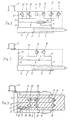
- Fig. L shows the simplest embodiment of the control circuit according to the invention.
- Fig. 2 gives the circuit at pre see further adjustable throttle bodies again.
- 3 illustrates a compact design of the control circuit according to the invention within the piston of the piston / cylinder unit.
- Fig. 4 represents a further embodiment variant, etc. in one of Fig. 2 analog throttle circuit.
- 5 finally illustrates a very simple embodiment of the control circuit according to the invention.
- a connecting line 6 leading to the other piston chamber 5 leads from the cylinder chamber 4 free of the piston rod, in which a first check valve is installed, which prevents the hydraulic fluid from flowing back from the cylinder chamber 5 into the cylinder chamber 4.
- a line 8 leads from the connecting line 6 to a compensation space 9, which serves to compensate for the different volumes of the two cylinder spaces 4 and 5.
- a further controllable throttle element 10 is provided in line 8, the throttle effect of which can be controlled by means of an adjusting screw (not shown).
- a further line 11 leading to the compensation space 9 branches off from the cylinder space 4 or from the connecting line 6, in which a further check valve 12, which closes the direct flow of the hydraulic fluid from the cylinder space 4 into the compensation space 9, is arranged.
- This further check valve can be bypassed via a bypass line 13, in which a first controllable throttle element 14 is arranged.
- the first check valve 7 is replaced by a shuttle valve 15, which is designed as a double-acting check valve.
- the connecting line 6 opens into this shuttle valve 15 at one end and leads back between the two valve seats of the shuttle valve to the other cylinder chamber.
- line 8 leads to the first controllable throttle element.
- the shuttle valve is preloaded by a spring 16 such that it has the return flow from the cylinder chamber 5 shown in the drawing in the cylinder space 4 preventing position.
- Both in the line 8 and in the bypass line 13 are parallel to the further controllable throttle element 10 or to the first controllable throttle element 14, a throttle element 17 and 18 that closes when the pressure rises, and a throttle element 19 and 20 that opens when the pressure increases further switched on.
- the throttling elements 17 and 18 further close the flow, so that the respective piston movement is counteracted more strongly. If the pressure in the line 8 or the bypass line 13 increases further, the valves 19 and 20 open, as a result of which the joints are blocked due to excessive counterpressure and thus the safety of the users is increased.
- the throttling elements 17, 18, 19, 20 can be reset to the starting position by means of a spring when the pressure conditions in the line 8 or the bypass line 13 fall back to the normal value.
- a throttle element 21 having a predetermined passage width is provided in the connecting line 6 between the cylinder chamber 4 and the cylinder chamber 5, with no check valve being arranged in this connecting line in a modification of the other exemplary embodiments. Rather, a bypass line 22 which bypasses the further adjustable throttle element 10 is provided, in which a check valve 23 is arranged, which blocks a flow of liquid from the cylinder space 5 to the compensation space 9.
- the volume of liquid required for filling the cylinder space 5 becomes dependent on the flow resistance in the throttle 21 or the opposite flow resistance of the liquid. sucked into the adjustable throttle element 14 either via the connecting line 6 or via the bypass line 22 and the check valve 23. The difference in volume between the volume of liquid displaced from the cylinder space 4 and the volume of liquid required for filling the cylinder space 5 is fed to the compensation space 9 via the line 13 and the first adjustable throttle element 14.
- throttle 21 it is achieved in any case that a certain passage of liquid from one cylinder chamber to the other cylinder chamber can pass through with a uniform damping effect, so that with differently adjusted throttle bodies 10 and 14 abrupt transitions between the control of the inward movement and the outward movement of the piston in the Cylinders and vice versa are avoided.
- a further check valve 24 is arranged directly in the connecting line 25 between the cylinder space 5 having the piston rod 3 and the compensation space 9, the further adjustable throttle element 10 in a bypass line 26 bypassing the check valve 24 is located.
- the piston 2 is pushed into the cylinder 1, that is to say moved to the left as seen in FIG. 5, the liquid displaced from the cylinder chamber 4 is fed into the compensation chamber 9 via the first adjustable throttle element 14 and the line 13 pressed as one other flow through the check valve 12 is prevented.
- the cylinder chamber 5 located on the back of the piston is filled unhindered via the line 25 and the check valve 24 which opens from the compensation chamber 9.
- the piston is pulled out of the cylinder, that is to say seen in FIG.
Landscapes
- Health & Medical Sciences (AREA)
- Engineering & Computer Science (AREA)
- General Engineering & Computer Science (AREA)
- General Health & Medical Sciences (AREA)
- Vascular Medicine (AREA)
- Veterinary Medicine (AREA)
- Public Health (AREA)
- Cardiology (AREA)
- Oral & Maxillofacial Surgery (AREA)
- Transplantation (AREA)
- Biomedical Technology (AREA)
- Heart & Thoracic Surgery (AREA)
- Animal Behavior & Ethology (AREA)
- Life Sciences & Earth Sciences (AREA)
- General Physics & Mathematics (AREA)
- Mechanical Engineering (AREA)
- Physics & Mathematics (AREA)
- Automation & Control Theory (AREA)
- Prostheses (AREA)
- Fluid-Pressure Circuits (AREA)
- Valve Device For Special Equipments (AREA)
- Manipulator (AREA)
Applications Claiming Priority (2)
| Application Number | Priority Date | Filing Date | Title |
|---|---|---|---|
| AT2864/87 | 1987-10-30 | ||
| AT0286487A AT391801B (de) | 1987-10-30 | 1987-10-30 | Hydraulische steuerung |
Publications (3)
| Publication Number | Publication Date |
|---|---|
| EP0314668A2 true EP0314668A2 (fr) | 1989-05-03 |
| EP0314668A3 EP0314668A3 (en) | 1990-02-14 |
| EP0314668B1 EP0314668B1 (fr) | 1993-08-25 |
Family
ID=3541521
Family Applications (1)
| Application Number | Title | Priority Date | Filing Date |
|---|---|---|---|
| EP88890270A Expired - Lifetime EP0314668B1 (fr) | 1987-10-30 | 1988-10-28 | Commande hydraulique |
Country Status (7)
| Country | Link |
|---|---|
| US (1) | US4958705A (fr) |
| EP (1) | EP0314668B1 (fr) |
| JP (1) | JP2736080B2 (fr) |
| AT (2) | AT391801B (fr) |
| CA (1) | CA1332099C (fr) |
| DE (1) | DE3883481D1 (fr) |
| ES (1) | ES2045192T3 (fr) |
Cited By (5)
| Publication number | Priority date | Publication date | Assignee | Title |
|---|---|---|---|---|
| EP0728451A1 (fr) * | 1995-02-24 | 1996-08-28 | Otto Bock Orthopädische Industrie Besitz- und Verwaltungs-Kommanditgesellschaft | Articulation du genou freinée |
| FR2771624A1 (fr) * | 1996-05-17 | 1999-06-04 | Joseph L Molino | Prothese de membre inferieur |
| CN103846904A (zh) * | 2012-11-30 | 2014-06-11 | 中国科学院沈阳自动化研究所 | 一种用于控制水下液压机械手的伺服阀箱 |
| CN110561406A (zh) * | 2019-08-31 | 2019-12-13 | 华南理工大学 | 一种面向仿生人的人造肌肉双向驱动机构 |
| CN115898990A (zh) * | 2023-01-05 | 2023-04-04 | 中国人民解放军国防科技大学 | 一种仿生关节驱动液压系统 |
Families Citing this family (30)
| Publication number | Priority date | Publication date | Assignee | Title |
|---|---|---|---|---|
| US5103811A (en) * | 1990-07-09 | 1992-04-14 | Crupi Jr Theodore P | Body part or joint brace |
| FR2735018B1 (fr) * | 1995-06-09 | 1997-07-11 | Proteval | Piece prothetique pneumatique pour l'articulation du genou |
| JP3829264B2 (ja) * | 1996-03-19 | 2006-10-04 | 株式会社日立製作所 | 減衰力調整式油圧緩衝器 |
| US5800561A (en) * | 1996-05-15 | 1998-09-01 | Massachusetts Institute Of Technology | Power-assisted upper extremity orthosis |
| US6113642A (en) | 1996-06-27 | 2000-09-05 | Mauch, Inc. | Computer controlled hydraulic resistance device for a prosthesis and other apparatus |
| DE60112403T2 (de) | 2000-01-20 | 2006-06-01 | Massachusetts Institute Of Technology, Cambridge | Elektronisch gesteuerte kniegelenkprothese |
| WO2001072245A2 (fr) | 2000-03-29 | 2001-10-04 | Massachusetts Institute Of Technology | Prothese de genou adaptable a la vitesse et adaptable au patient |
| US6464048B1 (en) * | 2000-07-24 | 2002-10-15 | Tenneco Automotive Inc. | Solenoid actuated continuously variable shock absorber |
| US6666127B2 (en) | 2002-05-03 | 2003-12-23 | Muscle Tech Ltd. | Artificial muscle |
| US7736394B2 (en) | 2002-08-22 | 2010-06-15 | Victhom Human Bionics Inc. | Actuated prosthesis for amputees |
| US7314490B2 (en) | 2002-08-22 | 2008-01-01 | Victhom Human Bionics Inc. | Actuated leg prosthesis for above-knee amputees |
| US7198071B2 (en) | 2003-05-02 | 2007-04-03 | Össur Engineering, Inc. | Systems and methods of loading fluid in a prosthetic knee |
| US7815689B2 (en) | 2003-11-18 | 2010-10-19 | Victhom Human Bionics Inc. | Instrumented prosthetic foot |
| US20050107889A1 (en) | 2003-11-18 | 2005-05-19 | Stephane Bedard | Instrumented prosthetic foot |
| US7438164B2 (en) * | 2003-12-08 | 2008-10-21 | Tenneco Automotive Operating Company Inc. | Solenoid actuated continuously variable servo valve for adjusting damping in shock absorbers and struts |
| US7637959B2 (en) | 2004-02-12 | 2009-12-29 | össur hf | Systems and methods for adjusting the angle of a prosthetic ankle based on a measured surface angle |
| US20050283257A1 (en) * | 2004-03-10 | 2005-12-22 | Bisbee Charles R Iii | Control system and method for a prosthetic knee |
| WO2005087144A2 (fr) | 2004-03-10 | 2005-09-22 | össur hf | Systeme de commande et procede pour un genou prothetique |
| US20060136072A1 (en) | 2004-05-07 | 2006-06-22 | Bisbee Charles R Iii | Magnetorheologically actuated prosthetic knee |
| DE102004031562A1 (de) * | 2004-06-29 | 2006-02-16 | Otto Bock Healthcare Ip Gmbh & Co. Kg | Künstlicher Fuß |
| GB2420395A (en) * | 2004-11-18 | 2006-05-24 | Westland Helicopters | Vibration damping apparatus for a helicopter rotor system |
| CA2592042C (fr) | 2004-12-22 | 2014-12-16 | Oessur Hf | Systemes et procedes de traitement du mouvement de membre |
| US8801802B2 (en) | 2005-02-16 | 2014-08-12 | össur hf | System and method for data communication with a mechatronic device |
| SE528516C2 (sv) | 2005-04-19 | 2006-12-05 | Lisa Gramnaes | Kombinerat aktivt och passivt benprotessystem samt en metod för att utföra en rörelsecykel med ett sådant system |
| WO2007027808A2 (fr) | 2005-09-01 | 2007-03-08 | össur hf | Systeme et methode pour determiner des transitions de terrain |
| US10842653B2 (en) | 2007-09-19 | 2020-11-24 | Ability Dynamics, Llc | Vacuum system for a prosthetic foot |
| CN102036626B (zh) | 2008-03-24 | 2014-07-02 | 奥瑟Hf公司 | 经股的假肢系统和用于操作该系统的方法 |
| US9561118B2 (en) | 2013-02-26 | 2017-02-07 | össur hf | Prosthetic foot with enhanced stability and elastic energy return |
| DE102018103884A1 (de) * | 2018-02-21 | 2019-08-22 | Otto Bock Healthcare Products Gmbh | Hydraulikaktuator |
| GB2588116B (en) * | 2019-10-07 | 2022-02-23 | Caterpillar Global Mining Llc | Method and apparatus for operating a machine work tool |
Family Cites Families (10)
| Publication number | Priority date | Publication date | Assignee | Title |
|---|---|---|---|---|
| US2859451A (en) * | 1956-11-05 | 1958-11-11 | Hans A Mauch | Hydraulic system |
| US4051558A (en) * | 1976-06-30 | 1977-10-04 | The United States Of America As Represented By The United States National Aeronautics And Space Administration | Mechanical energy storage device for hip disarticulation |
| US4266639A (en) * | 1979-05-10 | 1981-05-12 | International Telephone And Telegraph Corporation | Quick response hydraulic shock suppressor for piping systems |
| FR2531175B1 (fr) * | 1982-07-27 | 1986-04-04 | Bennes Marrel | Valve pilotee pour le freinage ou la limitation de vitesse dans un circuit hydraulique |
| EP0146550A4 (fr) * | 1982-10-20 | 1987-06-25 | Donald Maxwell Culley | Amortisseur de vibration. |
| SE458945B (sv) * | 1985-02-18 | 1989-05-22 | Vaexjoe Protes Ab | Hydraulanordning,speciellt foer benprotes |
| JPS6234809A (ja) * | 1985-08-06 | 1987-02-14 | Kayaba Ind Co Ltd | 油圧緩衝装置 |
| NL8600211A (nl) * | 1986-01-30 | 1987-08-17 | White Power Prod Bv | Hydraulische schokdemper. |
| GB2194309B (en) * | 1986-08-19 | 1990-02-14 | Wilson Sporting Goods | Hydraulic valve assembly for controlling a hydraulic cylinder |
| DE3718858A1 (de) * | 1987-06-05 | 1988-12-22 | Aros Hydraulik | Alternierender daempfer mit schwenkkolben |
-
1987
- 1987-10-30 AT AT0286487A patent/AT391801B/de not_active IP Right Cessation
-
1988
- 1988-10-28 CA CA000581672A patent/CA1332099C/fr not_active Expired - Fee Related
- 1988-10-28 US US07/264,213 patent/US4958705A/en not_active Expired - Lifetime
- 1988-10-28 EP EP88890270A patent/EP0314668B1/fr not_active Expired - Lifetime
- 1988-10-28 DE DE88890270T patent/DE3883481D1/de not_active Expired - Fee Related
- 1988-10-28 AT AT88890270T patent/ATE93595T1/de not_active IP Right Cessation
- 1988-10-28 ES ES88890270T patent/ES2045192T3/es not_active Expired - Lifetime
- 1988-10-31 JP JP63273399A patent/JP2736080B2/ja not_active Expired - Lifetime
Cited By (7)
| Publication number | Priority date | Publication date | Assignee | Title |
|---|---|---|---|---|
| EP0728451A1 (fr) * | 1995-02-24 | 1996-08-28 | Otto Bock Orthopädische Industrie Besitz- und Verwaltungs-Kommanditgesellschaft | Articulation du genou freinée |
| FR2771624A1 (fr) * | 1996-05-17 | 1999-06-04 | Joseph L Molino | Prothese de membre inferieur |
| CN103846904A (zh) * | 2012-11-30 | 2014-06-11 | 中国科学院沈阳自动化研究所 | 一种用于控制水下液压机械手的伺服阀箱 |
| CN110561406A (zh) * | 2019-08-31 | 2019-12-13 | 华南理工大学 | 一种面向仿生人的人造肌肉双向驱动机构 |
| CN110561406B (zh) * | 2019-08-31 | 2022-10-25 | 华南理工大学 | 一种面向仿生人的人造肌肉双向驱动机构 |
| CN115898990A (zh) * | 2023-01-05 | 2023-04-04 | 中国人民解放军国防科技大学 | 一种仿生关节驱动液压系统 |
| CN115898990B (zh) * | 2023-01-05 | 2023-05-23 | 中国人民解放军国防科技大学 | 一种仿生关节驱动液压系统 |
Also Published As
| Publication number | Publication date |
|---|---|
| DE3883481D1 (de) | 1993-09-30 |
| EP0314668B1 (fr) | 1993-08-25 |
| ES2045192T3 (es) | 1994-01-16 |
| US4958705A (en) | 1990-09-25 |
| EP0314668A3 (en) | 1990-02-14 |
| JP2736080B2 (ja) | 1998-04-02 |
| ATE93595T1 (de) | 1993-09-15 |
| AT391801B (de) | 1990-12-10 |
| ATA286487A (de) | 1990-06-15 |
| JPH01160549A (ja) | 1989-06-23 |
| CA1332099C (fr) | 1994-09-27 |
Similar Documents
| Publication | Publication Date | Title |
|---|---|---|
| AT391801B (de) | Hydraulische steuerung | |
| EP0126291B1 (fr) | Soupape commandée par un fluide sous pression | |
| DE2457451C2 (fr) | ||
| EP0016719B1 (fr) | Dispositif de commande pour moteur hydraulique | |
| EP0104567A2 (fr) | Vanne hydraulique automatique avec passage ajustable | |
| DE2327712A1 (de) | Druckmittel - versorgungseinrichtung | |
| DE3437217C2 (fr) | ||
| DE1430724C3 (de) | Lenksystem für ein Gelenkfahrzeug | |
| DE69503454T2 (de) | Bremsflüssigkeits-Drucksteuergerät | |
| DE1951429C3 (de) | Hydraulisches Steuersystem, insbesondere für mehrere Hydraulikmotore | |
| DE1173751B (de) | Steuereinrichtung fuer vorzugsweise mehrere von einer Pumpe versorgte hydraulische Antriebe | |
| DE69407704T2 (de) | Durchflussregelventil | |
| DE3420674A1 (de) | Druckversorgungseinrichtung fuer ein hydrauliksystem | |
| DE4328283C2 (de) | Hydraulischer Steuerkreis | |
| DE2854593A1 (de) | Hydraulische vorrichtung | |
| DE2151837C2 (de) | Hydraulische Steuervorrichtung für die lastunabhängige Druchflußregulierung zu einem Verbraucher | |
| DE2655812A1 (de) | Hydraulischer steuerkreis mit in ihrer foerdermenge veraenderbarer pumpe | |
| DE2356414A1 (de) | Stromteiler | |
| DE2601583C3 (de) | Ventil für hydraulische Anlagen | |
| DE3221160A1 (de) | Aus zwei steuerbloecken bestehende steuerventileinrichtung fuer mehrere hydraulische antriebe, insbesondere von mobilgeraeten | |
| DE2357148A1 (de) | Hydraulische schaltungsanordnung | |
| DE10341356B4 (de) | Vorspannventil mit zumindest zwei Schaltstufen sowie hydraulische Betätigungsanordnung | |
| DE322384C (de) | Steuerung fuer den Entlastungsschieber einer Turbinenentlastungsvorrichtung mit schnellem OEffnen und langsamem Schluss | |
| DE2442279A1 (de) | Steuervorrichtung zum steuern des flusses der druckfluessigkeit zu einer mehrzahl von hydraulischen stellgliedern | |
| DE3406781A1 (de) | Verbesserungen an zu arbeitszylindern geschalteten hydraulikkreisen |
Legal Events
| Date | Code | Title | Description |
|---|---|---|---|
| PUAI | Public reference made under article 153(3) epc to a published international application that has entered the european phase |
Free format text: ORIGINAL CODE: 0009012 |
|
| AK | Designated contracting states |
Kind code of ref document: A2 Designated state(s): AT BE CH DE ES FR GB IT LI LU NL SE |
|
| PUAL | Search report despatched |
Free format text: ORIGINAL CODE: 0009013 |
|
| AK | Designated contracting states |
Kind code of ref document: A3 Designated state(s): AT BE CH DE ES FR GB IT LI LU NL SE |
|
| RHK1 | Main classification (correction) |
Ipc: F16F 9/44 |
|
| 17P | Request for examination filed |
Effective date: 19900717 |
|
| 17Q | First examination report despatched |
Effective date: 19920217 |
|
| 17Q | First examination report despatched |
Effective date: 19921117 |
|
| GRAA | (expected) grant |
Free format text: ORIGINAL CODE: 0009210 |
|
| AK | Designated contracting states |
Kind code of ref document: B1 Designated state(s): AT BE CH DE ES FR GB IT LI LU NL SE |
|
| REF | Corresponds to: |
Ref document number: 93595 Country of ref document: AT Date of ref document: 19930915 Kind code of ref document: T |
|
| REF | Corresponds to: |
Ref document number: 3883481 Country of ref document: DE Date of ref document: 19930930 |
|
| ITF | It: translation for a ep patent filed | ||
| EPTA | Lu: last paid annual fee | ||
| ET | Fr: translation filed | ||
| GBT | Gb: translation of ep patent filed (gb section 77(6)(a)/1977) |
Effective date: 19931126 |
|
| REG | Reference to a national code |
Ref country code: ES Ref legal event code: FG2A Ref document number: 2045192 Country of ref document: ES Kind code of ref document: T3 |
|
| PLBE | No opposition filed within time limit |
Free format text: ORIGINAL CODE: 0009261 |
|
| STAA | Information on the status of an ep patent application or granted ep patent |
Free format text: STATUS: NO OPPOSITION FILED WITHIN TIME LIMIT |
|
| 26N | No opposition filed | ||
| EAL | Se: european patent in force in sweden |
Ref document number: 88890270.7 |
|
| PGFP | Annual fee paid to national office [announced via postgrant information from national office to epo] |
Ref country code: LU Payment date: 19951001 Year of fee payment: 8 |
|
| PGFP | Annual fee paid to national office [announced via postgrant information from national office to epo] |
Ref country code: BE Payment date: 19951027 Year of fee payment: 8 |
|
| PG25 | Lapsed in a contracting state [announced via postgrant information from national office to epo] |
Ref country code: LU Free format text: LAPSE BECAUSE OF NON-PAYMENT OF DUE FEES Effective date: 19961028 |
|
| PG25 | Lapsed in a contracting state [announced via postgrant information from national office to epo] |
Ref country code: BE Effective date: 19961031 |
|
| BERE | Be: lapsed |
Owner name: OTTO BOCK ORTHOPADISCHE INDUSTRIE BESITZ- UND VER Effective date: 19961031 |
|
| PGFP | Annual fee paid to national office [announced via postgrant information from national office to epo] |
Ref country code: ES Payment date: 20010828 Year of fee payment: 14 |
|
| PGFP | Annual fee paid to national office [announced via postgrant information from national office to epo] |
Ref country code: FR Payment date: 20010831 Year of fee payment: 14 |
|
| PGFP | Annual fee paid to national office [announced via postgrant information from national office to epo] |
Ref country code: SE Payment date: 20010911 Year of fee payment: 14 |
|
| PGFP | Annual fee paid to national office [announced via postgrant information from national office to epo] |
Ref country code: AT Payment date: 20011030 Year of fee payment: 14 |
|
| PGFP | Annual fee paid to national office [announced via postgrant information from national office to epo] |
Ref country code: NL Payment date: 20011031 Year of fee payment: 14 Ref country code: GB Payment date: 20011031 Year of fee payment: 14 |
|
| PGFP | Annual fee paid to national office [announced via postgrant information from national office to epo] |
Ref country code: DE Payment date: 20011130 Year of fee payment: 14 |
|
| REG | Reference to a national code |
Ref country code: GB Ref legal event code: IF02 |
|
| PGFP | Annual fee paid to national office [announced via postgrant information from national office to epo] |
Ref country code: CH Payment date: 20020109 Year of fee payment: 14 |
|
| PG25 | Lapsed in a contracting state [announced via postgrant information from national office to epo] |
Ref country code: GB Free format text: LAPSE BECAUSE OF NON-PAYMENT OF DUE FEES Effective date: 20021028 Ref country code: AT Free format text: LAPSE BECAUSE OF NON-PAYMENT OF DUE FEES Effective date: 20021028 |
|
| PG25 | Lapsed in a contracting state [announced via postgrant information from national office to epo] |
Ref country code: SE Free format text: LAPSE BECAUSE OF NON-PAYMENT OF DUE FEES Effective date: 20021029 Ref country code: ES Free format text: LAPSE BECAUSE OF NON-PAYMENT OF DUE FEES Effective date: 20021029 |
|
| PG25 | Lapsed in a contracting state [announced via postgrant information from national office to epo] |
Ref country code: LI Free format text: LAPSE BECAUSE OF NON-PAYMENT OF DUE FEES Effective date: 20021031 Ref country code: CH Free format text: LAPSE BECAUSE OF NON-PAYMENT OF DUE FEES Effective date: 20021031 |
|
| PG25 | Lapsed in a contracting state [announced via postgrant information from national office to epo] |
Ref country code: NL Free format text: LAPSE BECAUSE OF NON-PAYMENT OF DUE FEES Effective date: 20030501 Ref country code: DE Free format text: LAPSE BECAUSE OF NON-PAYMENT OF DUE FEES Effective date: 20030501 |
|
| EUG | Se: european patent has lapsed | ||
| REG | Reference to a national code |
Ref country code: CH Ref legal event code: PL |
|
| GBPC | Gb: european patent ceased through non-payment of renewal fee | ||
| PG25 | Lapsed in a contracting state [announced via postgrant information from national office to epo] |
Ref country code: FR Free format text: LAPSE BECAUSE OF NON-PAYMENT OF DUE FEES Effective date: 20030630 |
|
| NLV4 | Nl: lapsed or anulled due to non-payment of the annual fee |
Effective date: 20030501 |
|
| REG | Reference to a national code |
Ref country code: FR Ref legal event code: ST |
|
| REG | Reference to a national code |
Ref country code: ES Ref legal event code: FD2A Effective date: 20031112 |
|
| PG25 | Lapsed in a contracting state [announced via postgrant information from national office to epo] |
Ref country code: IT Free format text: LAPSE BECAUSE OF NON-PAYMENT OF DUE FEES Effective date: 20051028 |