EP0314676B1 - Verfahren zum herstellen von schwimmenden bauwerken und schwimmende elemente für deren herstellung - Google Patents
Verfahren zum herstellen von schwimmenden bauwerken und schwimmende elemente für deren herstellung Download PDFInfo
- Publication number
- EP0314676B1 EP0314676B1 EP87903446A EP87903446A EP0314676B1 EP 0314676 B1 EP0314676 B1 EP 0314676B1 EP 87903446 A EP87903446 A EP 87903446A EP 87903446 A EP87903446 A EP 87903446A EP 0314676 B1 EP0314676 B1 EP 0314676B1
- Authority
- EP
- European Patent Office
- Prior art keywords
- floating
- elements
- section
- construction
- coherent
- Prior art date
- Legal status (The legal status is an assumption and is not a legal conclusion. Google has not performed a legal analysis and makes no representation as to the accuracy of the status listed.)
- Expired
Links
- 238000007667 floating Methods 0.000 title claims abstract description 173
- 238000010276 construction Methods 0.000 title claims abstract description 53
- 238000000034 method Methods 0.000 title claims abstract description 14
- 238000005266 casting Methods 0.000 claims abstract description 14
- 239000011150 reinforced concrete Substances 0.000 claims abstract description 4
- 230000001427 coherent effect Effects 0.000 claims description 25
- 238000005192 partition Methods 0.000 claims description 12
- 239000000463 material Substances 0.000 claims description 11
- 230000003014 reinforcing effect Effects 0.000 claims description 5
- 230000008878 coupling Effects 0.000 claims description 3
- 238000010168 coupling process Methods 0.000 claims description 3
- 238000005859 coupling reaction Methods 0.000 claims description 3
- 230000002787 reinforcement Effects 0.000 description 9
- 239000004567 concrete Substances 0.000 description 6
- 238000004519 manufacturing process Methods 0.000 description 6
- 230000003116 impacting effect Effects 0.000 description 5
- 239000006261 foam material Substances 0.000 description 4
- XLYOFNOQVPJJNP-UHFFFAOYSA-N water Substances O XLYOFNOQVPJJNP-UHFFFAOYSA-N 0.000 description 4
- 238000009415 formwork Methods 0.000 description 2
- 238000004873 anchoring Methods 0.000 description 1
- 230000001419 dependent effect Effects 0.000 description 1
- 230000008092 positive effect Effects 0.000 description 1
- 230000002633 protecting effect Effects 0.000 description 1
- 239000007787 solid Substances 0.000 description 1
Images

Classifications
-
- B—PERFORMING OPERATIONS; TRANSPORTING
- B63—SHIPS OR OTHER WATERBORNE VESSELS; RELATED EQUIPMENT
- B63B—SHIPS OR OTHER WATERBORNE VESSELS; EQUIPMENT FOR SHIPPING
- B63B35/00—Vessels or similar floating structures specially adapted for specific purposes and not otherwise provided for
- B63B35/34—Pontoons
- B63B35/38—Rigidly-interconnected pontoons
Definitions
- the present invention relates to a process for producing on sea or lake of a coherent, floating construction, such as quays, buildings or the like, in that floating elements or floating sections are assembled, while they float on the sea or the lake, by means of locking means into a coherent self-floating raft construction while bounded by a coherent network of vertical, upwardly opening slots or ducts after which the network of slots or ducts are filled with a sea-durable casting material which is hardened with possible reinforcing means cast therein.
- a coherent, floating construction such as quays, buildings or the like
- the invention relates further to a floating element for carrying out the process according to the invention.
- a floating element is additionally known in the form of foam material or similar floating material, having vertical, plane side surfaces and a plane top surface and having vertical slots with openings to the top surface and to opposite side surfaces.
- the floating elements are adapted to be connected side-by-side to each other to form a compact formwork while bounded by through slots in all directions in the raft construction.
- In said slots there is cast sea-durable casting material with associated reinforcement, so that at the same time as there is constructed a network of cast bracing means between the floating elements to form a rigid raft construction, the network of bracing means can be included as a bracing component of the construction which is to be erected later on the raft construction.
- the objective was consequently to allow the floating elements to form a part of the raft construction as a coherent portion and thereby also as a coherent portion of the construction which is to be erected on the raft construction.
- the afore-mentioned solutions represent significant advantages, but in certain instances the afore-mentioned solutions involve considerable disadvantages, especially during the use of the finished building or the finished construction which should float on the sea.
- the buoyancy can be undesirably high in the finished construction, and in other cases the buoyancy can be insufficient in certain regions as a result of weakness in the material (foam material or similar floating material) of the floating elements.
- the floating elements will have no or the highest minimal positive effects on the finished construction. Constructively they are only suited to function in earlier building phases. They cannot be expected to contribute to the global constructional strength of the finished building since this contribution is proportionally extremely modest.
- the floating elements will not function either as a base or lowermost floor plan in the final building. Seen in this way, from the viewpoint of the final building, these floating elements will be an unnecessary appendage technically as well as economically.
- the aim is a process and floating elements where the use of foam material and similar floating material can be avoided, but where one can achieve nevertheless essentially equivalent advantages as in the known solutions without being burdened thereby with the same disadvantages.
- the objective is a solution where one constructs on the sea a raft construction having formwork characteristics for producing a braced raft construction.
- the aim is a solution where shell-shaped floating elements are used and where the floating elements can form a part of the final construction with mainly bracing and tightening and/or protecting properties, without increasing the buoyancy of the final construction.
- the process according to the invention is characterised in that a floating section of two or more floating elements is erected on a pontoon which floats on the sea or the lake, by means of locking means to form the intermediate, vertical, upwardly opening slots or ducts after which the floating section is caused to float, while the floating pontoon is submerged in the sea or the lake. Thereafter by means of further of the sail locking means the floating section is jointed together with one or more neighbouring sections to form the coherent raft construction with mutually aligned slots or ducts longitudinally and transversely of the raft construction.
- the floating elements can be fabricated directly on the mounting location on board the floating pontoon, preferably with simultaneous connection of two or more floating elements with the aid of the locking means into a coherent floating section. In this way the handling of the floating elements can be reduced to a minimum and for example the fabrication of the floating elements can be combined with a simultaneous jointing together of these into a coherent floating section in a practical manner.
- a floating section for carrying out the process according to the invention is characterised in that the floating element is made of relatively thin-walled, light weight reinforced concrete, has the form of a plane base member having a square cross-section and which along the edges is rigidly and tighly connected to mutually coherent, reinforced side members projecting vertically upwards which form an anchoring for locking means for mutually coupling together neighbouring floating elements, and flange-forming flaps which are adapted to form stops against a neighbouring floating element projecting laterally outwards relative to the side members.
- the said light weight floating elements that is to say thin-walled floating elements having an essentially shell-shaped design
- a suitable free board for the floating elements and for two or more floating elements which are jointed together to a larger floating section.
- the locking means between the floating elements and the floating sections can if necessary be utilised to adjust an intended straight line path of the slot or the duct between the rows of floating elements at the same time as the slots or the ducts are set with the desired breadth. Simultaneously one ensures that the bottom portions of the floating elements are set essentially in alignment with each other in a horizontal direction (if necessary combined with a local ballast loading). At the same time it is possible to ensure an equivalent rectilinear path between the floating elements in two main directions of the raft construction (longitudinal direction and breadth direction) by allowing the locking means to extend substantially parallel to the side members of the floating elements. Thereby one can ensure that tension and pressure forces are transmitted in the two main directions of the raft construction mainly through the side members. A considerable bracing of the floating elements can be achieved by bracing of the side members by the bottom member.
- the side members of the floating element are mutually braced by means of transverse bracing means, preferably in the form of reinforced partition members between each of the side members to form separate chambers in the floating element.
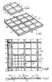
- a light weight, shell-shaped floating element 10 consisting of a square, horizontal base member 11, from which four rectilinear side members 12 project upwardly at right angles together with two rectilinear partition members 13 crossing mutually in the shape of a cross which extend at right angles to the side members 12.
- the side members 12 are arranged at a certain distance within the outer edge of the base member 11, so that they project freely outwards relative to four rectilinear flange-shaped flaps 14 of the side members.
- the floating element is fabricated into a construction of concrete with associated reinforcement.
- light weight concrete can be employed in the floating elements or in parts of these.
- certain portions of the reinforcement extend longitudinally and can for example be angled in an annular rectangular contour, while other portions of the reinforcement extend crosswise and continue in the base members 11, and in the partition members 13, and upwardly in the building which is later to be produced on the fashioned surface.
- relatively thin-walled concrete so that the floating element takes the form of a shell construction.
- Fig. 2 there is illustrated a system for jointing together four floating elements into a floating section 15 of larger square shape, the four floating elements impacting tightly together edge-to-edge.
- the floating section does not need in itself to be totally rigid, but can be permitted a certain movement by wave motion and the like. If necessary the elements can be cast together into a coherent floating section via a common bottom member. Alternatively the floating elements can be made separately and jointed together by means of locking means between adjacent side members of two neighbouring elements (as shown correspondingly in Fig. 7 and 8). In all instances provision is made for leaving mutually aligned, longitudinal and transverse slots or ducts 16a and 16b respectively between the floating elements.
- a floating pontoon 17 in the form of a working platform.
- the floating pontoon 16 is anchored by means of pieces of chain 18 to two opposite floats 19.
- the working pontoon 17 is adapted to form a solid, level foundation for the fabrication of the floating section 15 directly on this and if necessary also for the fabrication of the floating elements 10 directly on this, followed by a jointing together of the floating elements in the floating condition on the sea surface S into a coherent floating section 15.
- the floating elements can be made on land and transferred by crane or derrick to the working pontoon 17 for subsequent jointing together of four floating elements into a coherent floating section.
- each floating section can be jointed together in practice, but a module of two or four floating elements in each floating section (rectangular or square) is preferred on account of later jointing together of the floating sections into a coherent raft construction which can cover the area for a building or the like.
- Fig. 5 the working pontoon 17 is shown in a partially submerged condition and supported by floats 19.
- Fig. 6 the floating section is shown after this is caused to float, that is to say after the working pontoon is lowered substantially below the floating section and the working pontoon 17 and the floats 19 are removed.
- the working pontoon is adapted to be filled with compressed air from a source of compressed air not shown further with associated air supply pipes and/or emptied of water ballast by means of pumps.
- the valve arrangement for filling the pontoon with water or with air is not shown either, since this equipment is designed in a conventional manner.
- Fig. 7 and 8 the jointing together of several sections 15 is shown for sectional assembling of the raft construction, there being indicated a first type of locking means 20 which extends parallel to side members 12 of the floating elements and a second type of locking means 21 which extends in alignment with the partition members 13.
- a first type of locking means 20 which extends parallel to side members 12 of the floating elements
- a second type of locking means 21 which extends in alignment with the partition members 13.
- Fig. 7 it will be especially evident from Fig. 7 that one obtains through-going tension-absorbing and pressure-absorbing reinforcing means via the side members 12 and the locking means 20 and via the partition members 13 and the locking means 21, that is to say in the longitudinal direction as well as in the transverse direction of the raft construction.
- Fig. 9 there is shown in detail a jointing together of two floating elements.
- a pair of upper and lower locking means 20a, 20b for example in the form of pieces of reinforcing rod which are permanently welded or connected in another manner to fittings 20c, 20d fastened to the reinforcing rod 12a in side member 12 of the floating element.
- the locking means can consist of tension rods or similar axiallly regulatable locking means.
- a seal-forming wooden strip 23 which is fastened via a bolt 24 with nut 24a and stop disc 25 which forms an abutment against the upper side of the edge flaps 14.
- a water-durable joint material for example in the form of concrete.
- a coherent network-formed duct system in all directions of the raft construction.
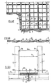
- tension-absorbing reinforcements 15a, 15b for example such as indicated in Fig. 10 and 11, there being cast with concrete into the duct system transverse and longitudinal foundation girders or foundation pedestals in coherent connection with the locking means 20 and 21 between the reinforcement in the floating elements.
- Fig. 10 and 11 there are employed separate edge-forming floating elements 31 which are jointed together with adjacent floating elements 10 in the raft construction in a manner equivalent to that shown in the mutual jointing together of the floating elements 10.
- the floating elements 31 can form supports for the end walls 27 or be provided with projections which form the end walls 27.
- the floating elements 31 with the side walls can form equivalent boundaries for the ducts 16a and 16b.
- the elements 31 are provided on account of the reduced dimension laterally with a substantially greater height (draught) than the elements 10.
- each individual floating element 10 such as indicated before the launching
- the floating elements provision is made for casting in fastening fitting for the locking means 20 and 21.
- the locking means for certain of the locking means, for example the four pairs of locking means 20 which connect four floating elements 10 at an impacting corner into a coherent floating section, the locking means can if desired be cast directly into side walls of the floating elements in a case where the floating elements and the floating section are made by casting on the working pontoon.
Landscapes
- Chemical & Material Sciences (AREA)
- Engineering & Computer Science (AREA)
- Combustion & Propulsion (AREA)
- Mechanical Engineering (AREA)
- Ocean & Marine Engineering (AREA)
- Bridges Or Land Bridges (AREA)
Claims (4)
Applications Claiming Priority (1)
| Application Number | Priority Date | Filing Date | Title |
|---|---|---|---|
| PCT/NO1987/000037 WO1988009284A1 (en) | 1987-05-18 | 1987-05-18 | Process for producing floating constructions and floating elements for the same |
Publications (2)
| Publication Number | Publication Date |
|---|---|
| EP0314676A1 EP0314676A1 (de) | 1989-05-10 |
| EP0314676B1 true EP0314676B1 (de) | 1991-09-11 |
Family
ID=19907447
Family Applications (1)
| Application Number | Title | Priority Date | Filing Date |
|---|---|---|---|
| EP87903446A Expired EP0314676B1 (de) | 1987-05-18 | 1987-05-18 | Verfahren zum herstellen von schwimmenden bauwerken und schwimmende elemente für deren herstellung |
Country Status (5)
| Country | Link |
|---|---|
| EP (1) | EP0314676B1 (de) |
| DE (1) | DE3772993D1 (de) |
| DK (1) | DK164583C (de) |
| FI (1) | FI890256A7 (de) |
| WO (1) | WO1988009284A1 (de) |
Families Citing this family (4)
| Publication number | Priority date | Publication date | Assignee | Title |
|---|---|---|---|---|
| NL2005108C2 (nl) * | 2010-03-05 | 2011-09-06 | Delta Archineering B V | Drijvende constructie, werkwijze voor het verschaffen hiervan en gebruik hiervan. |
| IT1399632B1 (it) * | 2010-04-21 | 2013-04-26 | Auto Nautica Service S R L | Metodo per la realizzazione di un'opera galleggiante e opera galleggiante cosi' realizzata |
| DE102011100627A1 (de) * | 2011-05-05 | 2012-11-08 | Ingenieurbüro ArmandPlan | Schwimmende Großplattform mit günstiger Öko- und Energiebilanz, Mulde als flutbares Trockendock sowie Herstellungsverfahren der Großplattform |
| CN103821121B (zh) * | 2014-02-14 | 2015-09-09 | 马献林 | 大型钢筋混凝土海洋平台及其制造方法 |
Family Cites Families (6)
| Publication number | Priority date | Publication date | Assignee | Title |
|---|---|---|---|---|
| US3315627A (en) * | 1965-10-24 | 1967-04-25 | Roberts Harold | Pneumatically operated floating dry dock |
| GB1288989A (de) * | 1969-11-24 | 1972-09-13 | Mitsui Shipbuilding Eng | |
| US3691974A (en) * | 1970-03-03 | 1972-09-19 | Twin City Shipyard Inc | Portable barge |
| US3951085A (en) * | 1973-08-06 | 1976-04-20 | Johnson Don E | Floating structure arrangement |
| US3962981A (en) * | 1975-01-20 | 1976-06-15 | Shoreline Precast Company | Barge factory |
| US4067285A (en) * | 1975-04-02 | 1978-01-10 | Jones Robert M | Modular floating structure |
-
1987
- 1987-05-18 DE DE8787903446T patent/DE3772993D1/de not_active Expired - Lifetime
- 1987-05-18 WO PCT/NO1987/000037 patent/WO1988009284A1/en not_active Ceased
- 1987-05-18 EP EP87903446A patent/EP0314676B1/de not_active Expired
-
1989
- 1989-01-17 DK DK019289A patent/DK164583C/da active
- 1989-01-18 FI FI890256A patent/FI890256A7/fi not_active Application Discontinuation
Also Published As
| Publication number | Publication date |
|---|---|
| WO1988009284A1 (en) | 1988-12-01 |
| DK19289A (da) | 1989-01-17 |
| DK164583B (da) | 1992-07-20 |
| FI890256A0 (fi) | 1989-01-18 |
| DK19289D0 (da) | 1989-01-17 |
| DE3772993D1 (de) | 1991-10-17 |
| FI890256A7 (fi) | 1989-01-18 |
| DK164583C (da) | 1992-12-07 |
| EP0314676A1 (de) | 1989-05-10 |
Similar Documents
| Publication | Publication Date | Title |
|---|---|---|
| US4318361A (en) | Lightweight concrete marine float and method of constructing same | |
| EP0379383B1 (de) | Verfahren zum Herstellen von Unterwasserbauwerken | |
| US3665882A (en) | Buoyant structure | |
| EP1404927B1 (de) | Modulare marine-anordnung | |
| KR101009264B1 (ko) | 수상구조물용 부유조립체 | |
| US6205945B1 (en) | Floating dock including buoyant wharf modules and method of making such modules | |
| US5213447A (en) | Interconnecting water platform | |
| US5713296A (en) | Lightweight concrete dock | |
| US4548153A (en) | Buoyant concrete foundation and method therefor | |
| KR101028711B1 (ko) | 부유식 방파제 및 그 시공방법 | |
| EP0314676B1 (de) | Verfahren zum herstellen von schwimmenden bauwerken und schwimmende elemente für deren herstellung | |
| US7883294B1 (en) | Monolithic dock and method for making | |
| CN101272945A (zh) | 漂浮结构 | |
| US4303352A (en) | Method for the building and putting in place of a sea platform with a gravity resting base, and means for implementing such a method | |
| KR101675487B1 (ko) | 해상부유구조물용 부력체 시공방법 | |
| JP7820533B2 (ja) | 特殊な生産現場で重力式構造物(gbs)を生産するための方法 | |
| US9505468B2 (en) | Floating platform | |
| KR102674923B1 (ko) | 강화바닥판을 구비한 바지선 | |
| EP0361615B1 (de) | Schwimmende Parallelepiped-Struktur | |
| JPS6310243B2 (de) | ||
| JP2000212969A (ja) | ハニカム構造のケ―ソン基礎 | |
| SU1749373A1 (ru) | Гравитационна платформа и способ ее монтажа | |
| JPH10140580A (ja) | コンクリート基礎用の型枠とそれを用いた基礎の施工方法 | |
| JPS58138832A (ja) | ケーソン堤の構築方法 | |
| JP2024508480A (ja) | 浮遊可能なコンクリートブロック構造物及びその製作方法 |
Legal Events
| Date | Code | Title | Description |
|---|---|---|---|
| PUAI | Public reference made under article 153(3) epc to a published international application that has entered the european phase |
Free format text: ORIGINAL CODE: 0009012 |
|
| 17P | Request for examination filed |
Effective date: 19890116 |
|
| AK | Designated contracting states |
Kind code of ref document: A1 Designated state(s): BE DE FR GB IT NL SE |
|
| 17Q | First examination report despatched |
Effective date: 19910118 |
|
| GRAA | (expected) grant |
Free format text: ORIGINAL CODE: 0009210 |
|
| ITF | It: translation for a ep patent filed | ||
| AK | Designated contracting states |
Kind code of ref document: B1 Designated state(s): BE DE FR GB IT NL SE |
|
| REF | Corresponds to: |
Ref document number: 3772993 Country of ref document: DE Date of ref document: 19911017 |
|
| ET | Fr: translation filed | ||
| PGFP | Annual fee paid to national office [announced via postgrant information from national office to epo] |
Ref country code: FR Payment date: 19920504 Year of fee payment: 6 |
|
| PGFP | Annual fee paid to national office [announced via postgrant information from national office to epo] |
Ref country code: GB Payment date: 19920505 Year of fee payment: 6 Ref country code: BE Payment date: 19920505 Year of fee payment: 6 |
|
| PGFP | Annual fee paid to national office [announced via postgrant information from national office to epo] |
Ref country code: SE Payment date: 19920518 Year of fee payment: 6 |
|
| PGFP | Annual fee paid to national office [announced via postgrant information from national office to epo] |
Ref country code: NL Payment date: 19920531 Year of fee payment: 6 |
|
| PGFP | Annual fee paid to national office [announced via postgrant information from national office to epo] |
Ref country code: DE Payment date: 19920625 Year of fee payment: 6 |
|
| PLBE | No opposition filed within time limit |
Free format text: ORIGINAL CODE: 0009261 |
|
| STAA | Information on the status of an ep patent application or granted ep patent |
Free format text: STATUS: NO OPPOSITION FILED WITHIN TIME LIMIT |
|
| 26N | No opposition filed | ||
| PG25 | Lapsed in a contracting state [announced via postgrant information from national office to epo] |
Ref country code: GB Effective date: 19930518 |
|
| PG25 | Lapsed in a contracting state [announced via postgrant information from national office to epo] |
Ref country code: SE Effective date: 19930519 |
|
| PG25 | Lapsed in a contracting state [announced via postgrant information from national office to epo] |
Ref country code: BE Effective date: 19930531 |
|
| BERE | Be: lapsed |
Owner name: BRUGGER OYSTEIN Effective date: 19930531 |
|
| PG25 | Lapsed in a contracting state [announced via postgrant information from national office to epo] |
Ref country code: NL Effective date: 19931201 |
|
| GBPC | Gb: european patent ceased through non-payment of renewal fee |
Effective date: 19930519 |
|
| NLV4 | Nl: lapsed or anulled due to non-payment of the annual fee | ||
| PG25 | Lapsed in a contracting state [announced via postgrant information from national office to epo] |
Ref country code: FR Effective date: 19940131 |
|
| PG25 | Lapsed in a contracting state [announced via postgrant information from national office to epo] |
Ref country code: DE Effective date: 19940201 |
|
| REG | Reference to a national code |
Ref country code: FR Ref legal event code: ST |
|
| EUG | Se: european patent has lapsed |
Ref document number: 87903446.0 Effective date: 19931210 |
|
| PG25 | Lapsed in a contracting state [announced via postgrant information from national office to epo] |
Ref country code: IT Free format text: LAPSE BECAUSE OF NON-PAYMENT OF DUE FEES;WARNING: LAPSES OF ITALIAN PATENTS WITH EFFECTIVE DATE BEFORE 2007 MAY HAVE OCCURRED AT ANY TIME BEFORE 2007. THE CORRECT EFFECTIVE DATE MAY BE DIFFERENT FROM THE ONE RECORDED. Effective date: 20050518 |