EP0314911B1 - Frein à disque à garnitures partielles - Google Patents
Frein à disque à garnitures partielles Download PDFInfo
- Publication number
- EP0314911B1 EP0314911B1 EP88115632A EP88115632A EP0314911B1 EP 0314911 B1 EP0314911 B1 EP 0314911B1 EP 88115632 A EP88115632 A EP 88115632A EP 88115632 A EP88115632 A EP 88115632A EP 0314911 B1 EP0314911 B1 EP 0314911B1
- Authority
- EP
- European Patent Office
- Prior art keywords
- brake
- housing
- spot
- type disc
- bridge
- Prior art date
- Legal status (The legal status is an assumption and is not a legal conclusion. Google has not performed a legal analysis and makes no representation as to the accuracy of the status listed.)
- Expired - Lifetime
Links
Images


Classifications
-
- F—MECHANICAL ENGINEERING; LIGHTING; HEATING; WEAPONS; BLASTING
- F16—ENGINEERING ELEMENTS AND UNITS; GENERAL MEASURES FOR PRODUCING AND MAINTAINING EFFECTIVE FUNCTIONING OF MACHINES OR INSTALLATIONS; THERMAL INSULATION IN GENERAL
- F16D—COUPLINGS FOR TRANSMITTING ROTATION; CLUTCHES; BRAKES
- F16D65/00—Parts or details
- F16D65/02—Braking members; Mounting thereof
- F16D65/04—Bands, shoes or pads; Pivots or supporting members therefor
- F16D65/092—Bands, shoes or pads; Pivots or supporting members therefor for axially-engaging brakes, e.g. disc brakes
- F16D65/095—Pivots or supporting members therefor
- F16D65/097—Resilient means interposed between pads and supporting members or other brake parts
- F16D65/0973—Resilient means interposed between pads and supporting members or other brake parts not subjected to brake forces
- F16D65/0974—Resilient means interposed between pads and supporting members or other brake parts not subjected to brake forces acting on or in the vicinity of the pad rim in a direction substantially transverse to the brake disc axis
- F16D65/0977—Springs made from sheet metal
-
- F—MECHANICAL ENGINEERING; LIGHTING; HEATING; WEAPONS; BLASTING
- F16—ENGINEERING ELEMENTS AND UNITS; GENERAL MEASURES FOR PRODUCING AND MAINTAINING EFFECTIVE FUNCTIONING OF MACHINES OR INSTALLATIONS; THERMAL INSULATION IN GENERAL
- F16D—COUPLINGS FOR TRANSMITTING ROTATION; CLUTCHES; BRAKES
- F16D55/00—Brakes with substantially-radial braking surfaces pressed together in axial direction, e.g. disc brakes
- F16D55/02—Brakes with substantially-radial braking surfaces pressed together in axial direction, e.g. disc brakes with axially-movable discs or pads pressed against axially-located rotating members
- F16D55/22—Brakes with substantially-radial braking surfaces pressed together in axial direction, e.g. disc brakes with axially-movable discs or pads pressed against axially-located rotating members by clamping an axially-located rotating disc between movable braking members, e.g. movable brake discs or brake pads
- F16D55/224—Brakes with substantially-radial braking surfaces pressed together in axial direction, e.g. disc brakes with axially-movable discs or pads pressed against axially-located rotating members by clamping an axially-located rotating disc between movable braking members, e.g. movable brake discs or brake pads with a common actuating member for the braking members
- F16D55/225—Brakes with substantially-radial braking surfaces pressed together in axial direction, e.g. disc brakes with axially-movable discs or pads pressed against axially-located rotating members by clamping an axially-located rotating disc between movable braking members, e.g. movable brake discs or brake pads with a common actuating member for the braking members the braking members being brake pads
- F16D55/226—Brakes with substantially-radial braking surfaces pressed together in axial direction, e.g. disc brakes with axially-movable discs or pads pressed against axially-located rotating members by clamping an axially-located rotating disc between movable braking members, e.g. movable brake discs or brake pads with a common actuating member for the braking members the braking members being brake pads in which the common actuating member is moved axially, e.g. floating caliper disc brakes
- F16D55/2265—Brakes with substantially-radial braking surfaces pressed together in axial direction, e.g. disc brakes with axially-movable discs or pads pressed against axially-located rotating members by clamping an axially-located rotating disc between movable braking members, e.g. movable brake discs or brake pads with a common actuating member for the braking members the braking members being brake pads in which the common actuating member is moved axially, e.g. floating caliper disc brakes the axial movement being guided by one or more pins engaging bores in the brake support or the brake housing
-
- F—MECHANICAL ENGINEERING; LIGHTING; HEATING; WEAPONS; BLASTING
- F16—ENGINEERING ELEMENTS AND UNITS; GENERAL MEASURES FOR PRODUCING AND MAINTAINING EFFECTIVE FUNCTIONING OF MACHINES OR INSTALLATIONS; THERMAL INSULATION IN GENERAL
- F16D—COUPLINGS FOR TRANSMITTING ROTATION; CLUTCHES; BRAKES
- F16D55/00—Brakes with substantially-radial braking surfaces pressed together in axial direction, e.g. disc brakes
- F16D2055/0004—Parts or details of disc brakes
- F16D2055/0008—Brake supports
-
- F—MECHANICAL ENGINEERING; LIGHTING; HEATING; WEAPONS; BLASTING
- F16—ENGINEERING ELEMENTS AND UNITS; GENERAL MEASURES FOR PRODUCING AND MAINTAINING EFFECTIVE FUNCTIONING OF MACHINES OR INSTALLATIONS; THERMAL INSULATION IN GENERAL
- F16D—COUPLINGS FOR TRANSMITTING ROTATION; CLUTCHES; BRAKES
- F16D55/00—Brakes with substantially-radial braking surfaces pressed together in axial direction, e.g. disc brakes
- F16D2055/0004—Parts or details of disc brakes
- F16D2055/0016—Brake calipers
-
- F—MECHANICAL ENGINEERING; LIGHTING; HEATING; WEAPONS; BLASTING
- F16—ENGINEERING ELEMENTS AND UNITS; GENERAL MEASURES FOR PRODUCING AND MAINTAINING EFFECTIVE FUNCTIONING OF MACHINES OR INSTALLATIONS; THERMAL INSULATION IN GENERAL
- F16D—COUPLINGS FOR TRANSMITTING ROTATION; CLUTCHES; BRAKES
- F16D55/00—Brakes with substantially-radial braking surfaces pressed together in axial direction, e.g. disc brakes
- F16D2055/0004—Parts or details of disc brakes
- F16D2055/0041—Resilient elements interposed directly between the actuating member and the brake support, e.g. anti-rattle springs
Definitions
- the invention is therefore based on a brake of the type resulting from the preamble of the main claim and has set itself the task of providing such a brake measures that allow a minimization of the bridge thickness and at the same time reduce the inclined wear and noise of the brake pads during the braking process.
- the invention therefore consists in providing, on the one hand, a possibility that at least one of the brake pads can pull on the saddle opening in such a way that the force is transmitted to the carrier via the saddle, and on the other hand, the two stress-relieved areas provided with openings to arrange the housing bridge in a tangential plane through the center of gravity of the housing bridge.
- the invention is particularly recommended in cooperation with the combination of features according to claim 4, wherein the carrier is essentially formed by the steering knuckle, with which the pivot pin was also combined or forms part of the steering knuckle.
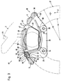
- the housing 1 shows a housing bridge 2, 3, 4 of a housing 1 with three bridge arms 2, 3, 4. Two openings 5, 6 are arranged between the bridge arms 2, 3, 4 in the region of neutral zones of the housing 1, also called low-stress zones. In the openings 5.6 there are two brake carrier arms 7.8 arranged.
- a piston-cylinder unit presses a piston with an active circle 9 and a center point 10.
- the housing 1 has a housing bridge height 11, a housing bridge width 12 and a housing bridge thickness 13. When the brake is applied, a moment from an application force multiplied by the distance 15 acts between the center of the piston 10 and the center of the housing bridge 14. With the same brake width as with brakes with external support arms 7, 8, stresses when the brake is actuated can be greatly reduced or the bridge thickness 13 can be minimized.
- FIG. 2 shows a partial-pad disc brake 16 with a saddle which overlaps a U-shaped brake disc 17, a piston-cylinder unit 18, 19 with a piston 18 and a cylinder 19 and a brake carrier 20.
- the piston 18 presses a brake pad 21, which is a Carrier plate 22 and a friction lining 23 have, directly and with the help of a leg 24 of the housing 1, a second brake lining 25, which has a further carrier plate 26 and a further friction lining 27, with the friction lining 27 indirectly against the brake disk 17.
- the housing 1 moved with the piston-cylinder unit 18, 19 with the aid of a pin guide 29 and a pin 30 relative to the brake carrier 20.
- the bolt 30 is in a bore 31 of the brake carrier 20 releasably or permanently attached.
- the bolt guide 29 is arranged in an eye 32 of the housing 1.
- the housing 1 with the pin guide 29 slide on the pin 30 when the brake is actuated.
- the partial lining disc brake is arranged in a rim with an edge 33.
- the brake carrier 20 has bores 34, 35, by means of which the brake carrier 20 is rigidly connected to a vehicle axle or suspension.
- the housing 1 is advantageously mounted on the bolt 30 of the brake carrier 20 so that it can rotate about a point 36.
- the bolt 30 can preferably be fastened directly to the vehicle axle, so that the region 39 of the brake carrier 20 is omitted.
- the brake carrier 20 is divided into three regions 37, 38 and 39, the regions 37 and 38 having an L-shaped profile with respect to one another, and the region 39 adjoining the region 38 at an obtuse angle 40.
- the area 39 is weak because it does not need to absorb braking forces.
- the rotation serves to open the saddle and change the pads 21, 25.
- the brake lining 21 is pressed with its friction lining 23 against the brake disc 17, which rotates in the direction 41 when the car is moving forward.
- the brake disc 17 has a friction surface 42 with radii 43 and 44.
- the housing 1 has the bridge arms 2, 3 and 4, the brake carrier 20 has the arm 7.
- the carrier plate 22 of the brake pad 21 has ends 45.46 on the bridge arm 3, grooves 47.48, which are located on projections 49.50 Support bridge arm 3.
- the end 46 has a further projection 51 and surfaces 52, 53 and 54, which are located on surfaces 55-57 support the brake arm 7.
- the projection 51 is arranged such that the brake pads 21, 25 can be pivoted with the housing 1 and can be axially detached from the housing 1 after the housing 1 has been folded up.
- the carrier plate 22 of the brake pad 21 is advantageously supported in the chronological order, first of all, on the bridge arm 3 and then on the brake carrier arm 7 when the brake is actuated in the forward direction.
- the end 46 of the brake linings 21, 25 is advantageously supported on the bridge arm 3 and, via the bridge arm 2, on the brake carrier arm 7.
- the housing 1 is held on its bridge arm 2 by a spring 58 in the working position.
- the spring 58 is arranged on the brake carrier arm 7 via a bolt 59. Furthermore, the spring 58 is supported on the end 46 of the plate 22 and 26 of the brake pad 21 and 25.
- the bolt 59 is arranged in an opening 60 of the brake carrier arm.
- the diameter of the opening 60 is larger than the diameter of the bolt 59, so that after the spring 58 has been pressed down in the direction 61, the bolt 59 can be inserted into the opening 60 of the brake carrier arm 7 and, after the spring 58 has springed back, the bolt 59 advantageously into a spring bed 62 comes to rest, which prevents the bolt from slipping axially.
- Fig. 4 shows the partial pad disc brake 16 with the housing 1 in plan view.
- the bridge arms 2, 3 and 4 extend over the brake disc 17 and are connected to one another on the side opposite the piston 18.
- the housing 1 can be pivoted about the bolt 30 after the spring 58 has been released.
- the spring 58 is detachably arranged on the brake carrier arm 7 with the releasable bolt 59.
- the spring 58 has an essentially rectangular part 63 in the area of the brake lining plates 22, 26 and an essentially trapezoidal part 64 in the area of the caliper arm 2.
- the rectangular part 63 is supported on both plates 22, 26 of the brake pads 21, 25.
- the spring bed 62 prevents the bolt 59 from axially slipping out in one of the directions 65, 66.
- Recesses 67, 68 are on the bridge arm 3 for assembly or disassembly of the brake pads 21, 25 in the opened state.
Landscapes
- Engineering & Computer Science (AREA)
- General Engineering & Computer Science (AREA)
- Mechanical Engineering (AREA)
- Braking Arrangements (AREA)
Claims (10)
- Frein à disque à garnitures partielles (16), comprenant un étrier (1), qui entoure en forme de U un disque de frein, une unité à piston et cylindre, qui applique deux garnitures de frein (23, 25) sur le disque de frein (17), la première (23) directement et la seconde (25) indirectement, par l'intermédiaire de l'étrier, et un support de frein (20) qui comporte un bras de support de frein (7) faisant saillie au-dessus du disque de frein (17), tandis que, dans au moins une première zone des ponts (2, 3, 4) de l'étrier, il est prévu un premier passage (5) dans lequel fait saillie le bras (7) du support de frein, sur lequel prend appui au moins la première (21) des deux garnitures de frein (21, 25), et que, dans une seconde zone des ponts (2, 3, 4) de l'étrier qui est décalée tangentiellement par rapport à la première, il est prévu un second passage (6) dans lequel fait saillie, en vue de son guidage, une extrémité (45) d'au moins la première garniture de frein (21), des contraintes relativement faibles régnant dans ces deux zones dans lesquelles des passages (5, 6) sont prévus, caractérisé en ce qu'au moins la première garniture de frein (21) est guidée sur le bord du second passage (6) et en ce que les zones soumises à de faibles contraintes s'étendent dans un plan tangentiel passant par le centre de gravité (14) de l'étrier.
- Frein à disque à garnitures partielles suivant la revendication 1, caractérisé en ce que l'étrier (1) est agencé de façon à pouvoir basculer autour d'une broche (30) qui est disposée du côté de l'arrivée par rapport à la direction de rotation en marche avant (41) du disque de frein (17).
- Frein à disque à garnitures partielles suivant l'une des revendications précédentes, caractérisé en ce que, lors d'un mouvement de basculement (figure 3, en trait interrompu) de l'étrier (1), les garnitures de frein (22, 26) sont maintenues sur cet étrier (1).
- Frein à disque à garnitures partielles suivant l'une des revendications 2 et 3, caractérisé en ce que la broche (30) est reliée directement à la fusée d'essieu.
- Frein à disque à garnitures partielles suivant l'une des revendications précédentes, caractérisé en ce que, du côté de la sortie par rapport à la direction de rotation en marche avant (41) du disque de frein (17), il est prévu un verrouillage (58, 59) qui, dans la position de verrouillage, empêche un soulèvement de l'étrier (1) par basculement.
- Frein à disque à garnitures partielles suivant la revendication 5, caractérisé en ce que le verrouillage (58, 59) comprend un ressort (58) qui est en appui sur l'étrier (1) et qui est maintenu dans le support (20) d'une manière séparable.
- Frein à disque à garnitures partielles suivant la revendication 6, caractérisé en ce que le ressort (58) est éventuellement en outre en appui sur au moins l'une des garnitures de frein (22, 26) et empêche ainsi un cliquetis de cette garniture de frein.
- Frein à disque à garnitures partielles suivant la revendication 7, caractérisé en ce que le ressort (58) applique la garniture de frein (22, 26) en appui dans la direction radiale sur l'étrier (1).
- Frein à disque à garnitures partielles suivant l'une des revendications 6 à 8, caractérisé en ce que le ressort (58) est maintenu par une broche de maintien (59) qui est ancrée d'une manière séparable dans une ouverture (60) du support (20).
- Frein à disque à garnitures partielles suivant l'une des revendications 1 à 9, caractérisé en ce que les dimensions du frein sont choisies de façon telle que, lors d'un actionnement du frein, la garniture de frein (21) prend appui d'abord sur les ponts (2, 3, 4) de l'étrier, puis, par l'intermédiaire du déplacement du pont, sur le bras (7) du support de frein, directement (conduite en marche avant) ou indirectement par l'intermédiaire des ponts (2, 3, 4) de l'étrier.
Applications Claiming Priority (2)
| Application Number | Priority Date | Filing Date | Title |
|---|---|---|---|
| DE3737080 | 1987-10-31 | ||
| DE19873737080 DE3737080A1 (de) | 1987-10-31 | 1987-10-31 | Teilbelag-scheibenbremse |
Publications (2)
| Publication Number | Publication Date |
|---|---|
| EP0314911A1 EP0314911A1 (fr) | 1989-05-10 |
| EP0314911B1 true EP0314911B1 (fr) | 1993-04-28 |
Family
ID=6339567
Family Applications (1)
| Application Number | Title | Priority Date | Filing Date |
|---|---|---|---|
| EP88115632A Expired - Lifetime EP0314911B1 (fr) | 1987-10-31 | 1988-09-23 | Frein à disque à garnitures partielles |
Country Status (4)
| Country | Link |
|---|---|
| EP (1) | EP0314911B1 (fr) |
| JP (1) | JPH01145436A (fr) |
| BR (1) | BR8805081A (fr) |
| DE (2) | DE3737080A1 (fr) |
Families Citing this family (2)
| Publication number | Priority date | Publication date | Assignee | Title |
|---|---|---|---|---|
| JPH04109233U (ja) * | 1991-03-07 | 1992-09-22 | 日信工業株式会社 | 車両用デイスクブレ―キのキヤリパボデイ |
| JP2021063527A (ja) * | 2019-10-11 | 2021-04-22 | 日信工業株式会社 | 車両用ディスクブレーキのキャリパボディ |
Citations (1)
| Publication number | Priority date | Publication date | Assignee | Title |
|---|---|---|---|---|
| US4540068A (en) * | 1983-02-22 | 1985-09-10 | Allied Corporation | Disc brake |
Family Cites Families (5)
| Publication number | Priority date | Publication date | Assignee | Title |
|---|---|---|---|---|
| GB1532572A (en) * | 1976-02-26 | 1978-11-15 | Girling Ltd | Sliding caliper disc brake |
| DE2804808C3 (de) * | 1978-02-04 | 1988-09-29 | Alfred Teves Gmbh, 6000 Frankfurt | Bremsbackenhalterung für eine Teilbelagscheibenbremse, insbesondere für Kraftfahrzeuge |
| US4476962A (en) * | 1982-12-16 | 1984-10-16 | Bendiberica S.A. | Disc brake having a sliding yoke |
| DE3520086A1 (de) * | 1985-06-05 | 1986-12-11 | Alfred Teves Gmbh, 6000 Frankfurt | Teilbelag-schwimmsattelbremse, insbesondere fuer kraftfahrzeuge |
| DE3540810C1 (de) * | 1985-11-16 | 1987-06-11 | Daimler Benz Ag | Schwimmsattel-Scheibenbremse |
-
1987
- 1987-10-31 DE DE19873737080 patent/DE3737080A1/de not_active Ceased
-
1988
- 1988-09-23 DE DE8888115632T patent/DE3880623D1/de not_active Expired - Fee Related
- 1988-09-23 EP EP88115632A patent/EP0314911B1/fr not_active Expired - Lifetime
- 1988-10-03 BR BR8805081A patent/BR8805081A/pt unknown
- 1988-10-31 JP JP63275994A patent/JPH01145436A/ja active Pending
Patent Citations (1)
| Publication number | Priority date | Publication date | Assignee | Title |
|---|---|---|---|---|
| US4540068A (en) * | 1983-02-22 | 1985-09-10 | Allied Corporation | Disc brake |
Also Published As
| Publication number | Publication date |
|---|---|
| JPH01145436A (ja) | 1989-06-07 |
| EP0314911A1 (fr) | 1989-05-10 |
| DE3880623D1 (de) | 1993-06-03 |
| BR8805081A (pt) | 1989-05-16 |
| DE3737080A1 (de) | 1989-05-11 |
Similar Documents
| Publication | Publication Date | Title |
|---|---|---|
| DE4126196A1 (de) | Schwimmrahmen-teilbelagscheibenbremse fuer hochleistungsfahrzeuge | |
| EP2252805B1 (fr) | Frein à disque garantissant un montage avec orientation correcte des garnitures de frein | |
| DE3540810C1 (de) | Schwimmsattel-Scheibenbremse | |
| EP0641949B1 (fr) | Frein à disque | |
| DE2229838A1 (de) | Scheibenbremse | |
| DE2039003A1 (de) | Scheibenkonstruktion bei einer Reibungskupplung oder -bremse | |
| DE1146382B (de) | Scheibenbremse | |
| DE3340442C2 (de) | Fahrwerks-Baugruppe für die Anbringung von Radachsen und Bremsen bei Kraftfahrzeugen | |
| DE2307537A1 (de) | Bremse mit einem reifenartigen abzubremsenden organ, insbesondere fuer kraftfahrzeuge | |
| DE2107519A1 (de) | Radaufhängung fur Fahrzeuge | |
| DE2547170A1 (de) | Schwimmsattel-scheibenbremse | |
| DE8519567U1 (de) | Scheibenbremse mit Bremssattel und durch Haken im Bremssattel befestigten Bremsbelägen | |
| DE2738581A1 (de) | Scheibenbremse | |
| DE4106957C2 (de) | Federnde Führung an einer Schwimmsattel-Teilbelagscheibenbremse | |
| DD245117A3 (de) | Ratterschutz-feder an einem bremsklotz einer teilbelagscheibenbremse | |
| DE102009027081A1 (de) | Vorrichtung zur Lagerung von Bremsbacken einer Trommelbremse | |
| WO1993003289A1 (fr) | Frein a disque a etrier flottant a agencement confortable des segments | |
| DE4402960C2 (de) | Scheibenbremse | |
| DE2828618A1 (de) | Federeinrichtung fuer eine trommelbremse | |
| DE69611574T2 (de) | Schwimmsattel-Scheibenbremse mit gestufter Bremsscheibe | |
| DE1932057A1 (de) | Teilbelagscheibenbremse insbesondere fuer Kraftfahrzeuge | |
| EP0674113A1 (fr) | Frein à tambour pour véhicules | |
| EP0469310A1 (fr) | Patin de frein pour freins à disque à garniture partielle | |
| DE2230574A1 (de) | Bremsbacke mit bremsbelag fuer scheibenbremsen von kraftfahrzeugen | |
| DE19650425B4 (de) | Bremsträger für eine Teilbelagscheibenbremse |
Legal Events
| Date | Code | Title | Description |
|---|---|---|---|
| PUAI | Public reference made under article 153(3) epc to a published international application that has entered the european phase |
Free format text: ORIGINAL CODE: 0009012 |
|
| 17P | Request for examination filed |
Effective date: 19880923 |
|
| AK | Designated contracting states |
Kind code of ref document: A1 Designated state(s): DE ES FR GB IT |
|
| 17Q | First examination report despatched |
Effective date: 19900608 |
|
| ITF | It: translation for a ep patent filed | ||
| GRAA | (expected) grant |
Free format text: ORIGINAL CODE: 0009210 |
|
| AK | Designated contracting states |
Kind code of ref document: B1 Designated state(s): DE ES FR GB IT |
|
| PG25 | Lapsed in a contracting state [announced via postgrant information from national office to epo] |
Ref country code: GB Effective date: 19930428 Ref country code: FR Effective date: 19930428 Ref country code: ES Free format text: THE PATENT HAS BEEN ANNULLED BY A DECISION OF A NATIONAL AUTHORITY Effective date: 19930428 |
|
| REF | Corresponds to: |
Ref document number: 3880623 Country of ref document: DE Date of ref document: 19930603 |
|
| EN | Fr: translation not filed | ||
| GBV | Gb: ep patent (uk) treated as always having been void in accordance with gb section 77(7)/1977 [no translation filed] |
Effective date: 19930428 |
|
| PLBE | No opposition filed within time limit |
Free format text: ORIGINAL CODE: 0009261 |
|
| STAA | Information on the status of an ep patent application or granted ep patent |
Free format text: STATUS: NO OPPOSITION FILED WITHIN TIME LIMIT |
|
| 26N | No opposition filed | ||
| PGFP | Annual fee paid to national office [announced via postgrant information from national office to epo] |
Ref country code: DE Payment date: 19980916 Year of fee payment: 11 |
|
| PG25 | Lapsed in a contracting state [announced via postgrant information from national office to epo] |
Ref country code: DE Free format text: LAPSE BECAUSE OF NON-PAYMENT OF DUE FEES Effective date: 20000701 |
|
| PG25 | Lapsed in a contracting state [announced via postgrant information from national office to epo] |
Ref country code: IT Free format text: LAPSE BECAUSE OF NON-PAYMENT OF DUE FEES;WARNING: LAPSES OF ITALIAN PATENTS WITH EFFECTIVE DATE BEFORE 2007 MAY HAVE OCCURRED AT ANY TIME BEFORE 2007. THE CORRECT EFFECTIVE DATE MAY BE DIFFERENT FROM THE ONE RECORDED. Effective date: 20050923 |