EP0314912B1 - Spreizdübel für die Verankerung in hinterschnittenen Bohrlöchern - Google Patents
Spreizdübel für die Verankerung in hinterschnittenen Bohrlöchern Download PDFInfo
- Publication number
- EP0314912B1 EP0314912B1 EP88115689A EP88115689A EP0314912B1 EP 0314912 B1 EP0314912 B1 EP 0314912B1 EP 88115689 A EP88115689 A EP 88115689A EP 88115689 A EP88115689 A EP 88115689A EP 0314912 B1 EP0314912 B1 EP 0314912B1
- Authority
- EP
- European Patent Office
- Prior art keywords
- expansion
- segments
- plug
- expansible
- shaft
- Prior art date
- Legal status (The legal status is an assumption and is not a legal conclusion. Google has not performed a legal analysis and makes no representation as to the accuracy of the status listed.)
- Expired - Lifetime
Links
- 238000004873 anchoring Methods 0.000 claims description 9
- 230000007704 transition Effects 0.000 claims description 3
- 230000000284 resting effect Effects 0.000 claims 1
- 238000009434 installation Methods 0.000 abstract 1
- 238000000034 method Methods 0.000 description 2
- 208000031872 Body Remains Diseases 0.000 description 1
- 238000005452 bending Methods 0.000 description 1
- 230000005540 biological transmission Effects 0.000 description 1
- 238000010276 construction Methods 0.000 description 1
- 230000014759 maintenance of location Effects 0.000 description 1
- 239000002184 metal Substances 0.000 description 1
Images
Classifications
-
- F—MECHANICAL ENGINEERING; LIGHTING; HEATING; WEAPONS; BLASTING
- F16—ENGINEERING ELEMENTS AND UNITS; GENERAL MEASURES FOR PRODUCING AND MAINTAINING EFFECTIVE FUNCTIONING OF MACHINES OR INSTALLATIONS; THERMAL INSULATION IN GENERAL
- F16B—DEVICES FOR FASTENING OR SECURING CONSTRUCTIONAL ELEMENTS OR MACHINE PARTS TOGETHER, e.g. NAILS, BOLTS, CIRCLIPS, CLAMPS, CLIPS OR WEDGES; JOINTS OR JOINTING
- F16B13/00—Dowels or other devices fastened in walls or the like by inserting them in holes made therein for that purpose
- F16B13/04—Dowels or other devices fastened in walls or the like by inserting them in holes made therein for that purpose with parts gripping in the hole or behind the reverse side of the wall after inserting from the front
- F16B13/08—Dowels or other devices fastened in walls or the like by inserting them in holes made therein for that purpose with parts gripping in the hole or behind the reverse side of the wall after inserting from the front with separate or non-separate gripping parts moved into their final position in relation to the body of the device without further manual operation
- F16B13/0858—Dowels or other devices fastened in walls or the like by inserting them in holes made therein for that purpose with parts gripping in the hole or behind the reverse side of the wall after inserting from the front with separate or non-separate gripping parts moved into their final position in relation to the body of the device without further manual operation with an expansible sleeve or dowel body driven against a tapered or spherical expander plug
-
- F—MECHANICAL ENGINEERING; LIGHTING; HEATING; WEAPONS; BLASTING
- F16—ENGINEERING ELEMENTS AND UNITS; GENERAL MEASURES FOR PRODUCING AND MAINTAINING EFFECTIVE FUNCTIONING OF MACHINES OR INSTALLATIONS; THERMAL INSULATION IN GENERAL
- F16B—DEVICES FOR FASTENING OR SECURING CONSTRUCTIONAL ELEMENTS OR MACHINE PARTS TOGETHER, e.g. NAILS, BOLTS, CIRCLIPS, CLAMPS, CLIPS OR WEDGES; JOINTS OR JOINTING
- F16B13/00—Dowels or other devices fastened in walls or the like by inserting them in holes made therein for that purpose
- F16B2013/007—Dowels or other devices fastened in walls or the like by inserting them in holes made therein for that purpose to be fastened in undercut holes
Definitions
- the invention relates to an expansion plug for anchoring in undercut boreholes according to the preamble of claim 1.
- Metallic expansion anchors can be anchored in conically widened boreholes almost without expansion pressure, with very high retention values being achieved due to the strong expansion of the expansion element.
- Known expansion anchors have an expansion cone, onto which an expansion sleeve can be opened by using a suitable driving tool.
- the dowel shaft protrudes from the borehole with a threaded element or the like and can be clamped there with an object to be fastened by means of a screw nut.
- the known expansion anchors which can be used in the borehole with conical undercut by means of impact mounting, require special drive-in tools which are each adapted to the diameter of the expansion anchor used.
- expansion anchor is also known for anchoring in undercut boreholes.
- This expansion dowel has an expansion body connected to the dowel shaft, on which expansion segments can be expanded. These expansion segments are integrally formed on the dowel shaft in the direction of the expansion body.
- the expansion body which is extended with a threaded shaft, is drawn into the expansion segments by means of a nut which is supported on the outer surface of the masonry and a turning tool which can be attached to the fastening part facing away from the expansion body.
- the expanding body is moved away from the bottom of the borehole towards the mouth of the borehole.
- the handling of two tools is therefore required, namely for the mother on the one hand and for the expansion body on the other.
- the anchoring takes place at a distance from the bottom of the borehole, which requires a deeper borehole that is not fully used for anchoring.
- the invention has for its object to provide an expansion anchor for anchoring in undercut boreholes, which is simple in construction and allows easy assembly.
- the expansion body is preferably designed as a threaded bolt with an expansion cone, the threaded section being screwed coaxially into the dowel shaft through the annular space formed by the expansion segments.
- the internal thread provided for this purpose on the dowel shaft has a sufficient depth so that the threaded bolt can be screwed in far enough to obtain a maximum expansion of the expansion segments.
- annular groove running outside is provided at the transition between spreading segments and dowel shaft.
- a particularly good sliding behavior between the expansion segments and the expansion body is obtained in that a slide ring is inserted into a recess or annular groove provided on the inner surface of the expansion segments.
- the slide ring can be made of metal or plastic with good sliding properties.
- An internal or external thread can be provided on the fastening part of the dowel shaft, which serves both as a means for attaching a turning tool and for tightening a fastening screw.
- an internal or external hexagon or a slot can also be used as a means for attaching a turning tool.
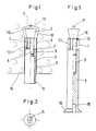
- the expansion dowel shown in Figure 1 consists of a threaded bolt 1 with expansion cone 2 and the dowel shaft 3.
- the threaded bolt 1 is screwed with its threaded portion 4 into an internal thread 5.
- this has molded-on expansion segments 6 which form a sleeve-shaped expansion area.
- an outer annular groove 7 is provided, which facilitates the bending of the expansion segments 6 during the expansion process.
- this has an inner bore 8 and a transverse slot 9, which is suitable for attaching a screwdriver.
- a turning tool for example a screwdriver
- a securing element 11 protruding from the end face of the expansion cone 2 presses against the bottom 12 of the borehole. This prevents the threaded bolt 1 from rotating together with the dowel shaft 3.
- an object to be fastened can be fastened to the wall 14 by inserting a screw into the internal thread 8.
- the securing element 11 is a wedge-shaped web. Distributed tips or the like could also serve as securing elements.
- FIG. 3 shows a further exemplary embodiment, which has a recess 15 on the inner surface of the expansion segments 6, into which a slide ring 16, preferably made of plastic, is inserted.
- the segments 6 are formed on the shaft 3 and separated from one another by longitudinal slots 7.
- the fastening part of the dowel shaft 3 has a hexagon socket 18 into which a turning tool, not shown here, can be used for rotating the dowel shaft 3.
- a flange 19 serves as the actual fastening element with which a slat, a frame or the like can be braced against a wall.
- the expansion plugs according to the invention are held securely in the borehole 10.
- a tensile force acting on the expansion dowel is transmitted via the expansion segments 6 and the threaded bolt 1 or via the threaded section 4.
- the entire cross-section of the expansion anchor for power transmission is thus also effective in the area of the threaded section 4. This enables extremely high load values to be achieved.
Landscapes
- Engineering & Computer Science (AREA)
- General Engineering & Computer Science (AREA)
- Mechanical Engineering (AREA)
- Dowels (AREA)
- Joining Of Building Structures In Genera (AREA)
- Perforating, Stamping-Out Or Severing By Means Other Than Cutting (AREA)
Priority Applications (1)
| Application Number | Priority Date | Filing Date | Title |
|---|---|---|---|
| AT88115689T ATE66288T1 (de) | 1987-11-05 | 1988-09-23 | Spreizduebel fuer die verankerung in hinterschnittenen bohrloechern. |
Applications Claiming Priority (2)
| Application Number | Priority Date | Filing Date | Title |
|---|---|---|---|
| DE19873737549 DE3737549A1 (de) | 1987-11-05 | 1987-11-05 | Spreizduebel fuer die verankerung in hinterschnittenen bohrloechern |
| DE3737549 | 1987-11-05 |
Publications (2)
| Publication Number | Publication Date |
|---|---|
| EP0314912A1 EP0314912A1 (de) | 1989-05-10 |
| EP0314912B1 true EP0314912B1 (de) | 1991-08-14 |
Family
ID=6339836
Family Applications (1)
| Application Number | Title | Priority Date | Filing Date |
|---|---|---|---|
| EP88115689A Expired - Lifetime EP0314912B1 (de) | 1987-11-05 | 1988-09-23 | Spreizdübel für die Verankerung in hinterschnittenen Bohrlöchern |
Country Status (7)
| Country | Link |
|---|---|
| US (1) | US4904134A (da) |
| EP (1) | EP0314912B1 (da) |
| JP (1) | JPH01150008A (da) |
| AT (1) | ATE66288T1 (da) |
| DE (1) | DE3737549A1 (da) |
| DK (1) | DK602688A (da) |
| ES (1) | ES2025750T3 (da) |
Families Citing this family (19)
| Publication number | Priority date | Publication date | Assignee | Title |
|---|---|---|---|---|
| DE3916611A1 (de) * | 1989-05-22 | 1990-11-29 | Fischer Artur Werke Gmbh | Eintreibvorrichtung fuer einschlaganker mit spreizhuelse |
| DE3921697A1 (de) * | 1989-07-01 | 1991-01-10 | Fischer Artur Werke Gmbh | Verankerung eines gewindebolzens mittels einer verbundmasse |
| DE3926229A1 (de) * | 1989-08-09 | 1991-02-14 | Fischer Artur Werke Gmbh | Spreizduebel |
| DE3932729A1 (de) * | 1989-09-30 | 1991-04-11 | Fischer Artur Werke Gmbh | Schlagspreizduebel |
| EP0422377A1 (de) * | 1989-10-10 | 1991-04-17 | fischerwerke Artur Fischer GmbH & Co. KG | Montageeinheit mit einem Spreizanker und einem Montagewerkzeug |
| DE3935166A1 (de) * | 1989-10-21 | 1991-04-25 | Fischer Artur Werke Gmbh | Schlagspreizduebel fuer die verankerung in hinterschnittenen bohrloechern |
| JPH07150643A (ja) * | 1992-04-22 | 1995-06-13 | Shinjiyou Seisakusho:Kk | コンクリート用アンカー |
| DE9303899U1 (de) * | 1993-03-17 | 1993-05-13 | Liebig, Heinrich, 6102 Pfungstadt | Durch Schlag setzbarer Spreizanker |
| US5413441A (en) * | 1993-07-19 | 1995-05-09 | United Industries Corporation | Hybrid eccentric wedge anchor |
| DE4400895A1 (de) * | 1994-01-14 | 1995-07-20 | Fischer Artur Werke Gmbh | Spreizdübel sowie Montageverfahren und Setzeinrichtung zu dessen Verankerung in einem Mauerwerk |
| GB2300454B (en) * | 1995-05-03 | 1999-06-23 | Rawlplug Co Ltd | Fasteners |
| DE19541564A1 (de) * | 1995-11-08 | 1997-05-15 | Fischer Artur Werke Gmbh | Metallspreizanker |
| DE19652278A1 (de) * | 1996-12-16 | 1998-06-18 | Hilti Ag | Selbstschneidender Hinterschnittdübel |
| DE10311079A1 (de) * | 2003-03-13 | 2004-09-30 | Powers Fasteners Europe Bv | Bohrvorrichtung |
| FR2868816B1 (fr) * | 2004-04-08 | 2008-05-09 | Prospection Et D Inv S Techniq | Procede de fixation d'un garde-corps par une cheville garde-corps, la cheville garde-corps et l'outil de fixation de la cheville garde-corps |
| US20080008553A1 (en) * | 2006-07-10 | 2008-01-10 | Robert Andrew Gillis | Self-drilling anchor screw and method of using the same |
| DE102007049744A1 (de) * | 2007-10-16 | 2009-04-23 | Fischerwerke Gmbh & Co. Kg | Spreizanker |
| TWM445093U (zh) * | 2012-08-31 | 2013-01-11 | Univ Far East | 可替換之壁虎 |
| US11536308B2 (en) * | 2018-12-03 | 2022-12-27 | Arrowhead Design and Innovation, LLC | Adjustable fastener system |
Citations (1)
| Publication number | Priority date | Publication date | Assignee | Title |
|---|---|---|---|---|
| DE2330538A1 (de) * | 1973-06-15 | 1975-04-30 | Artur Fischer | Befestigungselement zur verankerung in bauwerksteilen |
Family Cites Families (16)
| Publication number | Priority date | Publication date | Assignee | Title |
|---|---|---|---|---|
| DE7609714U1 (da) * | 1900-01-01 | Schaefers, Heinrich B., 2800 Bremen | ||
| US1379209A (en) * | 1919-06-21 | 1921-05-24 | John H Phillips | Anchor-drill bolt |
| US3107570A (en) * | 1961-10-11 | 1963-10-22 | Us Expansion Bolt Co | Fastening device |
| DE1988822U (de) * | 1966-10-06 | 1968-07-04 | Artur Fischer | Selbstbohrendes befestigungselement. |
| US4026186A (en) * | 1976-02-23 | 1977-05-31 | Illinois Tool Works Inc. | Self-drilling one-piece masonry anchor |
| DE2613499A1 (de) * | 1976-03-30 | 1977-10-13 | Heinrich B Schaefers | Bauwerksanker und verfahren zu seinem verankern |
| DE2745805A1 (de) * | 1977-10-12 | 1979-04-19 | Heinz Ehrhardt | Vorrichtung zur allgemeinen verankerung klemmnagel |
| DE2909749A1 (de) * | 1979-03-13 | 1980-09-18 | Stumpp & Kurz | Duebel und werkzeug zum befestigen des duebels |
| DE3025816A1 (de) * | 1980-07-08 | 1982-02-04 | Werkzeugfabrik Fritz Mächtle GmbH & Co KG, 7015 Korntal | Verfahren zum befestigen von lasten mittels spreizanker sowie spreizanker zur durchfuehrung dieses verfahrens |
| DE3124685A1 (de) * | 1981-06-24 | 1983-01-20 | Artur Dr.H.C. 7244 Waldachtal Fischer | Spreizduebel fuer die verankerung in konisch nach innen erweitert hergestellten bohrloechern |
| DE3146027A1 (de) * | 1981-11-20 | 1983-05-26 | Hilti AG, 9494 Schaan | Ankerbolzen mit bolzenkoerper und spreizhuelse |
| DE3246275A1 (de) * | 1982-12-14 | 1984-06-14 | Hilti Ag, Schaan | Spreizduebel |
| DE3411431A1 (de) * | 1984-03-28 | 1985-10-03 | Artur Dr.H.C. 7244 Waldachtal Fischer | Spreizduebel |
| EP0163120B1 (de) * | 1984-05-29 | 1988-06-08 | Fischerwerke Arthur Fischer GmbH & Co. KG | Spreizdübel |
| DE3535262A1 (de) * | 1985-10-03 | 1987-04-09 | Upat Max Langensiepen Kg | Spreizanker |
| US4636122A (en) * | 1985-12-12 | 1987-01-13 | Rooney James F | Joining and mounting device |
-
1987
- 1987-11-05 DE DE19873737549 patent/DE3737549A1/de not_active Withdrawn
-
1988
- 1988-09-23 EP EP88115689A patent/EP0314912B1/de not_active Expired - Lifetime
- 1988-09-23 AT AT88115689T patent/ATE66288T1/de active
- 1988-09-23 ES ES198888115689T patent/ES2025750T3/es not_active Expired - Lifetime
- 1988-10-28 DK DK602688A patent/DK602688A/da not_active Application Discontinuation
- 1988-11-01 JP JP63274644A patent/JPH01150008A/ja active Pending
- 1988-11-07 US US07/268,293 patent/US4904134A/en not_active Expired - Fee Related
Patent Citations (1)
| Publication number | Priority date | Publication date | Assignee | Title |
|---|---|---|---|---|
| DE2330538A1 (de) * | 1973-06-15 | 1975-04-30 | Artur Fischer | Befestigungselement zur verankerung in bauwerksteilen |
Also Published As
| Publication number | Publication date |
|---|---|
| DK602688A (da) | 1989-05-06 |
| ES2025750T3 (es) | 1992-04-01 |
| EP0314912A1 (de) | 1989-05-10 |
| DE3737549A1 (de) | 1989-05-18 |
| DK602688D0 (da) | 1988-10-28 |
| ATE66288T1 (de) | 1991-08-15 |
| US4904134A (en) | 1990-02-27 |
| JPH01150008A (ja) | 1989-06-13 |
Similar Documents
| Publication | Publication Date | Title |
|---|---|---|
| EP0314912B1 (de) | Spreizdübel für die Verankerung in hinterschnittenen Bohrlöchern | |
| DE8601106U1 (de) | Einstellbare Befestigungsvorrichtung zum Zusammenfügen von zwei Bauteilen | |
| EP0555542B1 (de) | Anker zur Verankerung mittels einer Verbundmasse in einem Bohrloch eines Betonteiles | |
| EP0297228A1 (de) | Spreizdübel für die Verankerung in konisch nach innen erweitert hergestellten Bohrlöchern | |
| EP0060973B1 (de) | Spreizdübel für die Verankerung in konisch nach innen erweitert hergestellten Bohrlöchern | |
| EP0331816B1 (de) | Schlagspreizdübel | |
| DE3840914A1 (de) | Befestigungssystem | |
| DE19520130A1 (de) | Formschlüssig setzbarer Hinterschnitt-Anker | |
| DE19749571B4 (de) | Ankervorrichtung zur Befestigung von dynamisch querbelasteten Gegenständen | |
| DE19536786A1 (de) | Befestigungselement mit Spreizelement | |
| DE4024963A1 (de) | Duebel mit einer duebelhuelse | |
| DE4400895A1 (de) | Spreizdübel sowie Montageverfahren und Setzeinrichtung zu dessen Verankerung in einem Mauerwerk | |
| AT6333U1 (de) | Einrichtung zur distanzierten befestigung von wärmedämmplatten | |
| DE3940638A1 (de) | Demontagevorrichtung | |
| EP0995914B1 (de) | Befestigungselement aus Metall mit Innengewinde für die Durchsteckmontage | |
| DE3620573A1 (de) | Vorrichtung zum befestigen eines gegenstandes an einer wand oder dgl. | |
| EP0156115B1 (de) | Spreizdübel | |
| DD267536A5 (de) | Duebel mit spreizhuelse | |
| EP0412257B1 (de) | Spreizdübel | |
| DE3820759A1 (de) | Spreizduebel zum einschlagen in ein bohrloch mit hinterschneidung | |
| DE4125577A1 (de) | Bohrung fuer einen spreizanker und bohrwerkzeug zu deren herstellung | |
| DE3930790A1 (de) | Einschlaganker | |
| DE19507058A1 (de) | Formschlüssig setzbarer Hinterschnitt-Anker | |
| DE20320553U1 (de) | Einrichtung zur distanzierten Befestigung von Wärmedämmplatten an Wänden oder Decken | |
| EP0893610B1 (de) | Spreizdübel |
Legal Events
| Date | Code | Title | Description |
|---|---|---|---|
| PUAI | Public reference made under article 153(3) epc to a published international application that has entered the european phase |
Free format text: ORIGINAL CODE: 0009012 |
|
| AK | Designated contracting states |
Kind code of ref document: A1 Designated state(s): AT BE CH ES FR GB IT LI NL SE |
|
| 17P | Request for examination filed |
Effective date: 19891023 |
|
| 17Q | First examination report despatched |
Effective date: 19900704 |
|
| ITF | It: translation for a ep patent filed | ||
| GRAA | (expected) grant |
Free format text: ORIGINAL CODE: 0009210 |
|
| AK | Designated contracting states |
Kind code of ref document: B1 Designated state(s): AT BE CH ES FR GB IT LI NL SE |
|
| REF | Corresponds to: |
Ref document number: 66288 Country of ref document: AT Date of ref document: 19910815 Kind code of ref document: T |
|
| ET | Fr: translation filed | ||
| GBT | Gb: translation of ep patent filed (gb section 77(6)(a)/1977) | ||
| REG | Reference to a national code |
Ref country code: ES Ref legal event code: FG2A Ref document number: 2025750 Country of ref document: ES Kind code of ref document: T3 |
|
| PLBE | No opposition filed within time limit |
Free format text: ORIGINAL CODE: 0009261 |
|
| STAA | Information on the status of an ep patent application or granted ep patent |
Free format text: STATUS: NO OPPOSITION FILED WITHIN TIME LIMIT |
|
| 26N | No opposition filed | ||
| PGFP | Annual fee paid to national office [announced via postgrant information from national office to epo] |
Ref country code: BE Payment date: 19920910 Year of fee payment: 5 |
|
| PGFP | Annual fee paid to national office [announced via postgrant information from national office to epo] |
Ref country code: SE Payment date: 19920916 Year of fee payment: 5 Ref country code: CH Payment date: 19920916 Year of fee payment: 5 |
|
| PGFP | Annual fee paid to national office [announced via postgrant information from national office to epo] |
Ref country code: FR Payment date: 19930804 Year of fee payment: 6 |
|
| PGFP | Annual fee paid to national office [announced via postgrant information from national office to epo] |
Ref country code: GB Payment date: 19930901 Year of fee payment: 6 |
|
| PGFP | Annual fee paid to national office [announced via postgrant information from national office to epo] |
Ref country code: AT Payment date: 19930915 Year of fee payment: 6 |
|
| PGFP | Annual fee paid to national office [announced via postgrant information from national office to epo] |
Ref country code: ES Payment date: 19930920 Year of fee payment: 6 |
|
| PG25 | Lapsed in a contracting state [announced via postgrant information from national office to epo] |
Ref country code: SE Effective date: 19930924 |
|
| PG25 | Lapsed in a contracting state [announced via postgrant information from national office to epo] |
Ref country code: LI Effective date: 19930930 Ref country code: CH Effective date: 19930930 Ref country code: BE Effective date: 19930930 |
|
| PGFP | Annual fee paid to national office [announced via postgrant information from national office to epo] |
Ref country code: NL Payment date: 19930930 Year of fee payment: 6 |
|
| BERE | Be: lapsed |
Owner name: FISCHERWERKE ARTUR FISCHER G.M.B.H. & CO. K.G. Effective date: 19930930 |
|
| REG | Reference to a national code |
Ref country code: CH Ref legal event code: PL |
|
| PG25 | Lapsed in a contracting state [announced via postgrant information from national office to epo] |
Ref country code: GB Effective date: 19940923 Ref country code: AT Effective date: 19940923 |
|
| PG25 | Lapsed in a contracting state [announced via postgrant information from national office to epo] |
Ref country code: ES Free format text: LAPSE BECAUSE OF EXPIRATION OF PROTECTION Effective date: 19940924 |
|
| EUG | Se: european patent has lapsed |
Ref document number: 88115689.7 Effective date: 19940410 |
|
| PG25 | Lapsed in a contracting state [announced via postgrant information from national office to epo] |
Ref country code: NL Effective date: 19950401 |
|
| NLV4 | Nl: lapsed or anulled due to non-payment of the annual fee | ||
| GBPC | Gb: european patent ceased through non-payment of renewal fee |
Effective date: 19940923 |
|
| PG25 | Lapsed in a contracting state [announced via postgrant information from national office to epo] |
Ref country code: FR Effective date: 19950531 |
|
| REG | Reference to a national code |
Ref country code: FR Ref legal event code: ST |
|
| REG | Reference to a national code |
Ref country code: ES Ref legal event code: FD2A Effective date: 19990601 |
|
| PG25 | Lapsed in a contracting state [announced via postgrant information from national office to epo] |
Ref country code: IT Free format text: LAPSE BECAUSE OF NON-PAYMENT OF DUE FEES;WARNING: LAPSES OF ITALIAN PATENTS WITH EFFECTIVE DATE BEFORE 2007 MAY HAVE OCCURRED AT ANY TIME BEFORE 2007. THE CORRECT EFFECTIVE DATE MAY BE DIFFERENT FROM THE ONE RECORDED. Effective date: 20050923 |