EP0314929A1 - Chaudière de récupération pour refroidir les gaz d'une oxydation partielle - Google Patents
Chaudière de récupération pour refroidir les gaz d'une oxydation partielle Download PDFInfo
- Publication number
- EP0314929A1 EP0314929A1 EP88116450A EP88116450A EP0314929A1 EP 0314929 A1 EP0314929 A1 EP 0314929A1 EP 88116450 A EP88116450 A EP 88116450A EP 88116450 A EP88116450 A EP 88116450A EP 0314929 A1 EP0314929 A1 EP 0314929A1
- Authority
- EP
- European Patent Office
- Prior art keywords
- waste heat
- gas
- heat boiler
- heat exchanger
- raw gas
- Prior art date
- Legal status (The legal status is an assumption and is not a legal conclusion. Google has not performed a legal analysis and makes no representation as to the accuracy of the status listed.)
- Granted
Links
- 239000007789 gas Substances 0.000 title claims abstract description 51
- 239000002918 waste heat Substances 0.000 title claims abstract description 25
- 230000003647 oxidation Effects 0.000 title claims description 10
- 238000007254 oxidation reaction Methods 0.000 title claims description 10
- 238000001816 cooling Methods 0.000 title claims description 4
- 238000004140 cleaning Methods 0.000 claims abstract description 11
- 238000010438 heat treatment Methods 0.000 claims abstract description 11
- 239000004071 soot Substances 0.000 claims abstract description 3
- 238000011144 upstream manufacturing Methods 0.000 claims description 3
- 239000003245 coal Substances 0.000 description 4
- 238000002309 gasification Methods 0.000 description 4
- 238000000034 method Methods 0.000 description 3
- XLYOFNOQVPJJNP-UHFFFAOYSA-N water Substances O XLYOFNOQVPJJNP-UHFFFAOYSA-N 0.000 description 3
- 238000002485 combustion reaction Methods 0.000 description 2
- 229920006395 saturated elastomer Polymers 0.000 description 2
- 238000010276 construction Methods 0.000 description 1
- 239000000428 dust Substances 0.000 description 1
- 230000005855 radiation Effects 0.000 description 1
- 238000000926 separation method Methods 0.000 description 1
- 239000007787 solid Substances 0.000 description 1
Images
Classifications
-
- C—CHEMISTRY; METALLURGY
- C10—PETROLEUM, GAS OR COKE INDUSTRIES; TECHNICAL GASES CONTAINING CARBON MONOXIDE; FUELS; LUBRICANTS; PEAT
- C10J—PRODUCTION OF PRODUCER GAS, WATER-GAS, SYNTHESIS GAS FROM SOLID CARBONACEOUS MATERIAL, OR MIXTURES CONTAINING THESE GASES; CARBURETTING AIR OR OTHER GASES
- C10J3/00—Production of combustible gases containing carbon monoxide from solid carbonaceous fuels
- C10J3/72—Other features
- C10J3/86—Other features combined with waste-heat boilers
-
- F—MECHANICAL ENGINEERING; LIGHTING; HEATING; WEAPONS; BLASTING
- F22—STEAM GENERATION
- F22B—METHODS OF STEAM GENERATION; STEAM BOILERS
- F22B1/00—Methods of steam generation characterised by form of heating method
- F22B1/02—Methods of steam generation characterised by form of heating method by exploitation of the heat content of hot heat carriers
- F22B1/18—Methods of steam generation characterised by form of heating method by exploitation of the heat content of hot heat carriers the heat carrier being a hot gas, e.g. waste gas such as exhaust gas of internal-combustion engines
- F22B1/1838—Methods of steam generation characterised by form of heating method by exploitation of the heat content of hot heat carriers the heat carrier being a hot gas, e.g. waste gas such as exhaust gas of internal-combustion engines the hot gas being under a high pressure, e.g. in chemical installations
- F22B1/1846—Methods of steam generation characterised by form of heating method by exploitation of the heat content of hot heat carriers the heat carrier being a hot gas, e.g. waste gas such as exhaust gas of internal-combustion engines the hot gas being under a high pressure, e.g. in chemical installations the hot gas being loaded with particles, e.g. waste heat boilers after a coal gasification plant
-
- F—MECHANICAL ENGINEERING; LIGHTING; HEATING; WEAPONS; BLASTING
- F22—STEAM GENERATION
- F22B—METHODS OF STEAM GENERATION; STEAM BOILERS
- F22B33/00—Steam-generation plants, e.g. comprising steam boilers of different types in mutual association
- F22B33/18—Combinations of steam boilers with other apparatus
-
- C—CHEMISTRY; METALLURGY
- C10—PETROLEUM, GAS OR COKE INDUSTRIES; TECHNICAL GASES CONTAINING CARBON MONOXIDE; FUELS; LUBRICANTS; PEAT
- C10J—PRODUCTION OF PRODUCER GAS, WATER-GAS, SYNTHESIS GAS FROM SOLID CARBONACEOUS MATERIAL, OR MIXTURES CONTAINING THESE GASES; CARBURETTING AIR OR OTHER GASES
- C10J2300/00—Details of gasification processes
- C10J2300/18—Details of the gasification process, e.g. loops, autothermal operation
- C10J2300/1861—Heat exchange between at least two process streams
-
- Y—GENERAL TAGGING OF NEW TECHNOLOGICAL DEVELOPMENTS; GENERAL TAGGING OF CROSS-SECTIONAL TECHNOLOGIES SPANNING OVER SEVERAL SECTIONS OF THE IPC; TECHNICAL SUBJECTS COVERED BY FORMER USPC CROSS-REFERENCE ART COLLECTIONS [XRACs] AND DIGESTS
- Y02—TECHNOLOGIES OR APPLICATIONS FOR MITIGATION OR ADAPTATION AGAINST CLIMATE CHANGE
- Y02P—CLIMATE CHANGE MITIGATION TECHNOLOGIES IN THE PRODUCTION OR PROCESSING OF GOODS
- Y02P20/00—Technologies relating to chemical industry
- Y02P20/10—Process efficiency
- Y02P20/129—Energy recovery, e.g. by cogeneration, H2recovery or pressure recovery turbines
Definitions
- the invention relates to a waste heat boiler for cooling partial oxidation raw gas with an integrated raw gas pure gas heat exchanger.
- this mode of operation is intended to transfer as much of the sensible heat as possible of the hot partial oxidation raw gas emerging from the coal gasification plant to the cold, dedusted and desulfurized clean gas which is fed to the combustion chamber of the gas turbine.
- the arrangement of the raw gas-pure gas heat exchanger within the waste heat boiler should make it possible, better than with conventional heat exchangers, to remove the incrustations and dirt that occur on the raw gas side of the heat exchanger surface.
- the present invention is therefore concerned with the constructive solution to this problem and pursues the goal of creating the most suitable design of a waste heat boiler, which is particularly suitable for carrying out the method described above.
- the waste heat boiler of the type mentioned at the outset which is used to achieve this object, is characterized in that the tubular body arranged in a pressure vessel is designed as a tubular basket, within which the raw gas-pure gas heat exchanger and heating surfaces are arranged.
- the raw gas-pure gas heat exchanger consists of one or more tubular coils and through which the clean gas flows.
- the raw gas-pure gas heat exchanger it is of course also possible for the raw gas-pure gas heat exchanger to have a different design, e.g. as a plate heat exchanger.
- the eco-heating surfaces can be connected upstream and / or downstream of the raw gas pure gas heat exchanger depending on the required operating conditions.
- waste heat boiler It is essential for the proper functioning of the waste heat boiler according to the invention that it is normally equipped with cleaning devices through which dirt on the heat exchanger or pipe surfaces can be removed even during ongoing operation.
- one or more wall-integrated soot blowers are arranged between the pressure vessel and the tube basket.
- mechanical cleaning devices such as, for example, the tube basket, the raw gas / pure gas heat exchanger and the eco-heating surfaces within the pressure vessel. Knocking devices to be provided.
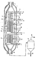
- the figure shows a section through an embodiment of the waste heat boiler according to the invention in a simplified representation.
- the figure shows the arrangement of all essential parts of the waste heat boiler without going into detail about their design. However, it can be assumed that these are known components that are familiar to the specialist world.
- the waste heat boiler shown in the figure consists of the pressure vessel 1, in which the tubular body designed as a tube basket 2 is arranged, which serves to generate waste heat.
- the pressure vessel 1 is designed so that it withstands the prevailing gasification pressure.
- the partial oxidation raw gas coming from the coal gasifier (not shown in the figure) enters the pressure vessel 1 from the top via the connection piece 3 with the appropriate pressure.
- the carburetor can already be provided with an integrated waste heat boiler radiation part.
- the feed water supply to the tube basket 2 takes place via the line 4 and the water vapor arising during the cooling of the partial oxidation gas is drawn off from the tube basket 2 via line 5.
- the raw gas-pure gas heat exchanger 6 is arranged within the tube basket 2.
- Example of this consists of two tubular coils 7a and 7b, through which the clean gas flows and which are connected to each other in terms of flow so that the dedusted and desulfurized cold clean gas enters the coils via line 8, flows through them and then in the heated state via the Line 9 is withdrawn again.
- the coils 7a and 7b are flowed around on both sides by the hot partial oxidation raw gas flowing downward, so that a particularly intensive heat exchange can take place between the raw gas and the clean gas, which, depending on the raw gas temperature, increases the clean gas temperature by 3oo to 5oo ° C leads.
- the heating surfaces 10 and 11 are arranged above and below the raw gas-pure gas heat exchanger 6, by means of which the sensible heat of the partial oxidation raw gas which is still present can also be used, for example for generating saturated steam.
- the necessary feed or boiler water supply takes place via lines 12 and 15 and the saturated steam discharge via lines 13 and 14.
- the cooled partial oxidation raw gas emerges from the waste heat boiler via the nozzle 16 and reaches the cyclone 17 for the purpose of dust separation, from which the cooled and dedusted gas is drawn off via the line 18 and fed to its further treatment.
- the wall-integrated sootblower 23 is arranged between the pressure vessel 1 and the tube basket 2.
- This can be a construction that has been described in DE-OS 33 12 599.
- mechanical cleaning devices 19, 20 and 21 are arranged in the area of the raw gas-pure gas heat exchanger 6 and the lower heating surfaces 11, which in this case are designed as knocking devices.
- the cleaning device 19 acts on the raw gas-pure gas heat exchanger 6, the cleaning device 20 on the tube basket 2 and the cleaning device 21 on the lower heating surfaces 11.
- the arrangement and the number of wall-integrated sootblowers 23 and the mechanical cleaning devices 19-21 will be adapted to the respective requirements in practice, so that their arrangement can also differ from the arrangement shown in the figure.
Landscapes
- Engineering & Computer Science (AREA)
- Chemical & Material Sciences (AREA)
- Thermal Sciences (AREA)
- Combustion & Propulsion (AREA)
- General Engineering & Computer Science (AREA)
- Mechanical Engineering (AREA)
- Physics & Mathematics (AREA)
- Sustainable Development (AREA)
- Sustainable Energy (AREA)
- Life Sciences & Earth Sciences (AREA)
- Oil, Petroleum & Natural Gas (AREA)
- Organic Chemistry (AREA)
- Heat-Exchange Devices With Radiators And Conduit Assemblies (AREA)
- Industrial Gases (AREA)
- Cyclones (AREA)
- Physical Or Chemical Processes And Apparatus (AREA)
Applications Claiming Priority (2)
| Application Number | Priority Date | Filing Date | Title |
|---|---|---|---|
| DE3737359 | 1987-11-04 | ||
| DE19873737359 DE3737359A1 (de) | 1987-11-04 | 1987-11-04 | Abhitzekessel zur kuehlung von partialoxidationsrohgas |
Publications (2)
| Publication Number | Publication Date |
|---|---|
| EP0314929A1 true EP0314929A1 (fr) | 1989-05-10 |
| EP0314929B1 EP0314929B1 (fr) | 1991-09-11 |
Family
ID=6339724
Family Applications (1)
| Application Number | Title | Priority Date | Filing Date |
|---|---|---|---|
| EP88116450A Expired - Lifetime EP0314929B1 (fr) | 1987-11-04 | 1988-10-05 | Chaudière de récupération pour refroidir les gaz d'une oxydation partielle |
Country Status (8)
| Country | Link |
|---|---|
| US (1) | US4920926A (fr) |
| EP (1) | EP0314929B1 (fr) |
| JP (1) | JP2680077B2 (fr) |
| DD (1) | DD275905A5 (fr) |
| DE (2) | DE3737359A1 (fr) |
| ES (1) | ES2025752T3 (fr) |
| PL (1) | PL275474A1 (fr) |
| ZA (1) | ZA886463B (fr) |
Cited By (5)
| Publication number | Priority date | Publication date | Assignee | Title |
|---|---|---|---|---|
| WO1991010106A1 (fr) * | 1990-01-05 | 1991-07-11 | Burmeister & Wain Energi A/S | Refroidisseur de gaz pour le transfert de chaleur par rayonnement |
| EP0645442A3 (en) * | 1993-09-28 | 1995-04-19 | Hitachi Ltd | A method of fuel gasification and an apparatus for performing such a method. |
| EP0635694A3 (fr) * | 1993-07-22 | 1995-06-28 | Steinmueller Gmbh L & C | Dispositif de refroidissement d'un gaz qui forme des dépÔts. |
| EP2336276A1 (fr) * | 2009-12-12 | 2011-06-22 | KOPF SynGas GmbH & Co. KG | Refroidisseur de gaz doté d'un dispositif de martelage |
| WO2012028550A1 (fr) * | 2010-08-30 | 2012-03-08 | Shell Internationale Research Maatschappij B.V. | Réacteur de gazéification |
Families Citing this family (7)
| Publication number | Priority date | Publication date | Assignee | Title |
|---|---|---|---|---|
| US5287915A (en) * | 1990-12-26 | 1994-02-22 | Shell Oil Company | Heat exchanger and method for removing deposits from inner surfaces thereof |
| US5941238A (en) * | 1997-02-25 | 1999-08-24 | Ada Tracy | Heat storage vessels for use with heat pumps and solar panels |
| US5762031A (en) * | 1997-04-28 | 1998-06-09 | Gurevich; Arkadiy M. | Vertical drum-type boiler with enhanced circulation |
| DE102006052301B4 (de) * | 2006-11-03 | 2013-05-16 | Maxxtec Ag | Reinigungsvorrichtung für Wärmeübertrager sowie Wärmeübertrager |
| EP2912394B1 (fr) * | 2012-10-18 | 2018-01-31 | Linde Aktiengesellschaft | Échangeur de chaleur avec plusieures entrées et procédé d'adaption de la surface chauffante de l'échangeur thermique |
| CN103017154B (zh) * | 2012-12-11 | 2015-12-09 | 中国东方电气集团有限公司 | 一种减轻高碱性煤种沾污的cfb-束状辐射锅炉 |
| USD767107S1 (en) * | 2013-03-15 | 2016-09-20 | Htp, Inc. | Heat exchanger |
Citations (7)
| Publication number | Priority date | Publication date | Assignee | Title |
|---|---|---|---|---|
| EP0012654A1 (fr) * | 1978-12-06 | 1980-06-25 | Creusot-Loire | Appareil de chauffe fournissant de la vapeur d'eau et du gaz chaud et application à une installation de raffinage |
| GB1590706A (en) * | 1978-05-19 | 1981-06-10 | Texaco Development Corp | Partial oxidation process |
| GB2068095A (en) * | 1980-01-23 | 1981-08-05 | Combustion Eng | Steam generating heat exchanger |
| GB2093175A (en) * | 1981-02-12 | 1982-08-25 | Texaco Development Corp | Synthesis gas cooler and waste heat boiler |
| FR2513146A1 (fr) * | 1981-09-22 | 1983-03-25 | Steinmueller Gmbh L & C | Dispositif d'abaissement de temperature et d'epuration d'un gaz au cours d'un processus de traitement |
| DE3248096A1 (de) * | 1982-12-24 | 1984-07-05 | M.A.N. Maschinenfabrik Augsburg-Nürnberg AG, 4200 Oberhausen | Stehende vorrichtung zum kuehlen von unter hohem druck stehenden gasen mit hohem staubanteil |
| DE8704049U1 (de) * | 1987-01-19 | 1987-05-07 | L. & C. Steinmüller GmbH, 5270 Gummersbach | Vorrichtung zur Prozeßgasabkühlung |
Family Cites Families (3)
| Publication number | Priority date | Publication date | Assignee | Title |
|---|---|---|---|---|
| DE3137586A1 (de) * | 1981-09-22 | 1983-04-07 | L. & C. Steinmüller GmbH, 5270 Gummersbach | "verfahren zum behandeln von aus einem vergasungsreaktor kommenden prozessgasen" |
| JPS6060506U (ja) * | 1983-10-04 | 1985-04-26 | 三菱重工業株式会社 | 炉壁貫通部構造 |
| DE3406893C3 (de) * | 1984-02-25 | 1996-02-08 | Babcock Energie Umwelt | Konvektionskühler |
-
1987
- 1987-11-04 DE DE19873737359 patent/DE3737359A1/de not_active Withdrawn
-
1988
- 1988-08-31 ZA ZA886463A patent/ZA886463B/xx unknown
- 1988-10-05 EP EP88116450A patent/EP0314929B1/fr not_active Expired - Lifetime
- 1988-10-05 ES ES198888116450T patent/ES2025752T3/es not_active Expired - Lifetime
- 1988-10-05 DE DE8888116450T patent/DE3864796D1/de not_active Expired - Fee Related
- 1988-10-25 PL PL27547488A patent/PL275474A1/xx unknown
- 1988-11-01 US US07/265,596 patent/US4920926A/en not_active Expired - Fee Related
- 1988-11-02 DD DD88321374A patent/DD275905A5/de not_active IP Right Cessation
- 1988-11-04 JP JP63277563A patent/JP2680077B2/ja not_active Expired - Lifetime
Patent Citations (7)
| Publication number | Priority date | Publication date | Assignee | Title |
|---|---|---|---|---|
| GB1590706A (en) * | 1978-05-19 | 1981-06-10 | Texaco Development Corp | Partial oxidation process |
| EP0012654A1 (fr) * | 1978-12-06 | 1980-06-25 | Creusot-Loire | Appareil de chauffe fournissant de la vapeur d'eau et du gaz chaud et application à une installation de raffinage |
| GB2068095A (en) * | 1980-01-23 | 1981-08-05 | Combustion Eng | Steam generating heat exchanger |
| GB2093175A (en) * | 1981-02-12 | 1982-08-25 | Texaco Development Corp | Synthesis gas cooler and waste heat boiler |
| FR2513146A1 (fr) * | 1981-09-22 | 1983-03-25 | Steinmueller Gmbh L & C | Dispositif d'abaissement de temperature et d'epuration d'un gaz au cours d'un processus de traitement |
| DE3248096A1 (de) * | 1982-12-24 | 1984-07-05 | M.A.N. Maschinenfabrik Augsburg-Nürnberg AG, 4200 Oberhausen | Stehende vorrichtung zum kuehlen von unter hohem druck stehenden gasen mit hohem staubanteil |
| DE8704049U1 (de) * | 1987-01-19 | 1987-05-07 | L. & C. Steinmüller GmbH, 5270 Gummersbach | Vorrichtung zur Prozeßgasabkühlung |
Cited By (10)
| Publication number | Priority date | Publication date | Assignee | Title |
|---|---|---|---|---|
| WO1991010106A1 (fr) * | 1990-01-05 | 1991-07-11 | Burmeister & Wain Energi A/S | Refroidisseur de gaz pour le transfert de chaleur par rayonnement |
| EP0635694A3 (fr) * | 1993-07-22 | 1995-06-28 | Steinmueller Gmbh L & C | Dispositif de refroidissement d'un gaz qui forme des dépÔts. |
| US5482110A (en) * | 1993-07-22 | 1996-01-09 | L. & C. Steinmuller Gmbh | Device for cooling a deposit-forming gas |
| EP0645442A3 (en) * | 1993-09-28 | 1995-04-19 | Hitachi Ltd | A method of fuel gasification and an apparatus for performing such a method. |
| US5676713A (en) * | 1993-09-28 | 1997-10-14 | Hitachi, Ltd. | Method of fuel gasification and an apparatus for performing such a method |
| EP2336276A1 (fr) * | 2009-12-12 | 2011-06-22 | KOPF SynGas GmbH & Co. KG | Refroidisseur de gaz doté d'un dispositif de martelage |
| WO2012028550A1 (fr) * | 2010-08-30 | 2012-03-08 | Shell Internationale Research Maatschappij B.V. | Réacteur de gazéification |
| AU2011298482B2 (en) * | 2010-08-30 | 2014-09-18 | Air Products And Chemicals, Inc. | Gasification reactor |
| US9267744B2 (en) | 2010-08-30 | 2016-02-23 | Shell Oil Company | Gasification reactor with a heat exchange unit provided with one or more fouling protection devices |
| KR101842429B1 (ko) | 2010-08-30 | 2018-05-14 | 쉘 인터내셔날 리써취 마트샤피지 비.브이. | 가스화 반응기 |
Also Published As
| Publication number | Publication date |
|---|---|
| DE3864796D1 (de) | 1991-10-17 |
| ZA886463B (en) | 1989-05-30 |
| US4920926A (en) | 1990-05-01 |
| DD275905A5 (de) | 1990-02-07 |
| ES2025752T3 (es) | 1992-04-01 |
| JP2680077B2 (ja) | 1997-11-19 |
| PL275474A1 (en) | 1989-05-02 |
| DE3737359A1 (de) | 1989-05-18 |
| EP0314929B1 (fr) | 1991-09-11 |
| JPH01155102A (ja) | 1989-06-19 |
Similar Documents
| Publication | Publication Date | Title |
|---|---|---|
| DE3147864C2 (de) | Abwärmekessel für die Kühlung von Synthesegas | |
| EP0606573B1 (fr) | Procédé pour refroidir et purifier du gaz contenant de fines particules, spécialement gaz de geulart ou d'un générateur de gaz et installation à cette fin | |
| EP0314929B1 (fr) | Chaudière de récupération pour refroidir les gaz d'une oxydation partielle | |
| DE2512233C3 (de) | Vorrichtung zur Ausnutzung der Rauchgase eines brennstoffbeheizten Heizungskessels | |
| EP0077851B1 (fr) | Appareil refroidisseur de gaz pour une installation de gazéification de charbon | |
| DE3442400C2 (fr) | ||
| EP0160161A1 (fr) | Echangeur de chaleur pour refroidir des gaz | |
| EP0616022B1 (fr) | Procédé pour la gazéification sous pression de combustibles finement divisés | |
| DE3643801C2 (fr) | ||
| DE2913748C2 (de) | Rohrbündelwärmetauscher zum Kühlen schlackenhaltiger Heißgase der Kohlevergasung | |
| DE2739562C2 (fr) | ||
| DE19607940A1 (de) | Dampfkondensierer für Backöfen und dergleichen | |
| DE4230124A1 (de) | Vorrichtung zur Kühlung von heißen Gasen | |
| DE2701166C2 (de) | "Verfahren und Anlage zum Reinigen des Rohgases eines Festbett-Druckgasgenerators" | |
| DE1109723B (de) | Senkrecht angeordneter Waermetauscher ohne Rohrplatten | |
| EP0035783B1 (fr) | Méthode et dispositif pour produire de l'électricité et de la chaleur à partir de combustible | |
| DE3447265A1 (de) | Verfahren und vorrichtung zur erzeugung von hochgespanntem und ueberhitztem dampf | |
| DE973504C (de) | Einrichtung zum Niederschlagen von ueberschuessigem Dampf bei Dampfkraftanlagen | |
| AT127482B (de) | Dampferzeuger oder Wärmeaustauscher. | |
| DE3430036C1 (de) | Rekuperativer Wärmeaustauscher | |
| DE609998C (de) | Heissdampfkuehler | |
| DE69420049T2 (de) | Ekonomiser eines rückgewinnungskessels | |
| DE741763C (de) | Wasserrohr-Strahlungskessel | |
| DE932513C (de) | Verfahren und Anlage zur Verbesserung der Waermeausnutzung bei Dampferzeugungsanlagen | |
| DE324081C (de) | Verfahren, Torf durch Erhitzen unter Druck leichter entwaesserbar zu machen |
Legal Events
| Date | Code | Title | Description |
|---|---|---|---|
| PUAI | Public reference made under article 153(3) epc to a published international application that has entered the european phase |
Free format text: ORIGINAL CODE: 0009012 |
|
| AK | Designated contracting states |
Kind code of ref document: A1 Designated state(s): DE ES GB IT NL |
|
| 17P | Request for examination filed |
Effective date: 19890321 |
|
| 17Q | First examination report despatched |
Effective date: 19900720 |
|
| GRAA | (expected) grant |
Free format text: ORIGINAL CODE: 0009210 |
|
| AK | Designated contracting states |
Kind code of ref document: B1 Designated state(s): DE ES GB IT NL |
|
| ITF | It: translation for a ep patent filed | ||
| REF | Corresponds to: |
Ref document number: 3864796 Country of ref document: DE Date of ref document: 19911017 |
|
| GBT | Gb: translation of ep patent filed (gb section 77(6)(a)/1977) | ||
| REG | Reference to a national code |
Ref country code: ES Ref legal event code: FG2A Ref document number: 2025752 Country of ref document: ES Kind code of ref document: T3 |
|
| PLBE | No opposition filed within time limit |
Free format text: ORIGINAL CODE: 0009261 |
|
| STAA | Information on the status of an ep patent application or granted ep patent |
Free format text: STATUS: NO OPPOSITION FILED WITHIN TIME LIMIT |
|
| 26N | No opposition filed | ||
| PGFP | Annual fee paid to national office [announced via postgrant information from national office to epo] |
Ref country code: GB Payment date: 19960916 Year of fee payment: 9 |
|
| PGFP | Annual fee paid to national office [announced via postgrant information from national office to epo] |
Ref country code: DE Payment date: 19960920 Year of fee payment: 9 |
|
| PGFP | Annual fee paid to national office [announced via postgrant information from national office to epo] |
Ref country code: NL Payment date: 19960930 Year of fee payment: 9 |
|
| PGFP | Annual fee paid to national office [announced via postgrant information from national office to epo] |
Ref country code: ES Payment date: 19961018 Year of fee payment: 9 |
|
| PG25 | Lapsed in a contracting state [announced via postgrant information from national office to epo] |
Ref country code: GB Free format text: LAPSE BECAUSE OF NON-PAYMENT OF DUE FEES Effective date: 19971005 |
|
| PG25 | Lapsed in a contracting state [announced via postgrant information from national office to epo] |
Ref country code: ES Free format text: LAPSE BECAUSE OF EXPIRATION OF PROTECTION Effective date: 19971006 |
|
| PG25 | Lapsed in a contracting state [announced via postgrant information from national office to epo] |
Ref country code: NL Free format text: LAPSE BECAUSE OF NON-PAYMENT OF DUE FEES Effective date: 19980501 |
|
| GBPC | Gb: european patent ceased through non-payment of renewal fee |
Effective date: 19971005 |
|
| NLV4 | Nl: lapsed or anulled due to non-payment of the annual fee |
Effective date: 19980501 |
|
| PG25 | Lapsed in a contracting state [announced via postgrant information from national office to epo] |
Ref country code: DE Free format text: LAPSE BECAUSE OF NON-PAYMENT OF DUE FEES Effective date: 19980701 |
|
| REG | Reference to a national code |
Ref country code: ES Ref legal event code: FD2A Effective date: 20010201 |
|
| PG25 | Lapsed in a contracting state [announced via postgrant information from national office to epo] |
Ref country code: IT Free format text: LAPSE BECAUSE OF NON-PAYMENT OF DUE FEES;WARNING: LAPSES OF ITALIAN PATENTS WITH EFFECTIVE DATE BEFORE 2007 MAY HAVE OCCURRED AT ANY TIME BEFORE 2007. THE CORRECT EFFECTIVE DATE MAY BE DIFFERENT FROM THE ONE RECORDED. Effective date: 20051005 |