EP0315002A2 - Entwurfsystem unter Verwendung von visueller Sprache - Google Patents
Entwurfsystem unter Verwendung von visueller Sprache Download PDFInfo
- Publication number
- EP0315002A2 EP0315002A2 EP19880117647 EP88117647A EP0315002A2 EP 0315002 A2 EP0315002 A2 EP 0315002A2 EP 19880117647 EP19880117647 EP 19880117647 EP 88117647 A EP88117647 A EP 88117647A EP 0315002 A2 EP0315002 A2 EP 0315002A2
- Authority
- EP
- European Patent Office
- Prior art keywords
- control system
- objects
- designing
- functional elements
- computer
- Prior art date
- Legal status (The legal status is an assumption and is not a legal conclusion. Google has not performed a legal analysis and makes no representation as to the accuracy of the status listed.)
- Withdrawn
Links
Images



Classifications
-
- G—PHYSICS
- G06—COMPUTING OR CALCULATING; COUNTING
- G06F—ELECTRIC DIGITAL DATA PROCESSING
- G06F17/00—Digital computing or data processing equipment or methods, specially adapted for specific functions
-
- G—PHYSICS
- G06—COMPUTING OR CALCULATING; COUNTING
- G06F—ELECTRIC DIGITAL DATA PROCESSING
- G06F30/00—Computer-aided design [CAD]
- G06F30/10—Geometric CAD
- G06F30/13—Architectural design, e.g. computer-aided architectural design [CAAD] related to design of buildings, bridges, landscapes, production plants or roads
-
- G—PHYSICS
- G06—COMPUTING OR CALCULATING; COUNTING
- G06F—ELECTRIC DIGITAL DATA PROCESSING
- G06F30/00—Computer-aided design [CAD]
- G06F30/20—Design optimisation, verification or simulation
Definitions
- the present invention relates to computer programs and more particularly to a computer program for designing, constructing and supporting systems of concurrent asynchronous processes.
- An automated factory is an example of a large complex interactive system.
- the design of such large complex systems is a significant technological challenge.
- the existing design aids have a variety of shortcomings and none of them address the entire problem.
- devices operate asynchronously and concurrently.
- the detailed actions of each device are managed by individual device controllers.
- the cell control logic must coordinate these device controllers usually by communicating with them over a network or direct link. Optimally, this cell logic must also provide the interface for operators and maintenance personnel.
- many applications require the cell to collect data about device performance and part quality. Communication with other parts of the factory may also be a requirement.
- a cell system in broad terms, consists of interacting asynchronous concurrent processes.
- the fundamental problem of cell control is creating logic for processes that operate and communicate in parallel.
- One of the stumbling blocks to complete factory automation is the inability to efficiently configure individual factory processes into productive, cooperative systems.
- One of the major problems to a coordinated factory automation program is that all processes do not move at the same pace or begin and end in the same field of time as other processes.
- Present systems do not include an integrated approach where control programs can be sent to cell controllers for execution on a local controller in an interactive environment. Stated differently, present systems do not provide an completely integrated and interactive specification, design, and operating environment.
- An object of the present invention is to provide an improved technique for designing complex systems.
- Another object is to be able to communicate the behavior and structure of a complex system.
- Another object is reduce the time required to design a completely functional system.
- Still another object is to provide a means to rapidly prototype a number of different approaches without spending time at the detail level.
- Yet another object is to provide diagnostic tools to enable one to discover quickly why an operational system is not behaving as desired.
- Another object is to speed up the integration process in a situation where one is trying to verify that each functional element relates accurately to the entire system.
- Still another object is to allow a user to deal with the creation and verification process in an integrated manner.
- the invention is a computer-based tool, in the form of a computer system and method, for designing, constructing and interacting with any system containing or comprising concurrent asynchronous processes, such as a factory operation.
- a variety of development and execution tools are supported.
- the invention features a highly visual user presentation of the structure, specification, and operation of a control system.
- the invention offers a user an interactive capability for rapid design, modification, and exploration of the operating characteristics of the system.
- the invention provides a set of integrated and interactive functional capabilities that help the user produce a complete detailed specification, offering rapid prototyping, comprehensive documentation, system emulation, functional animation, and system analysis capabilities.
- the invention provides an environment supporting the combination of:
- the invention provides a mechanism for capturing a representation of the system (RS) that is equivalent to an actual system (AS) - rather than a simulation of the actual system. This allows the tools according to the invention to perform tests and modifications on the RS instead of the AS, yet get accurate results.
- RS and AS are equivalent because AS is generated directly from RS by an automated process. Pressing a button for example in the RS environment can "create” the AS version or any selected portion of it, by “downloading” a translation of the RS version that can be executed by a programmable processor in the AS environment.
- AS and RS can interact is important. This allows RS to "take on” the "state” of AS whenever desired, through an "uploading" procedure, thereby reflecting accurately the condition of AS at a specific point in time. This permits an engineer to explore and dissect, so to speak, the RS version of the system without effecting the AS version that may still be in active operation. This is important for systems that cannot be easily taken out of service for diagnosis or maintenance.
- a specific embodiment of the invention disclosed herein is represented as it might be implemented using a Xerox 1185/86 Artificial Intelligent Work Station.
- the Xerox 1185/86 Work Station is a computer which provides an object-oriented applications platform and interconnections with other equipment as hereinafter explained.
- the present invention takes advantage of the speed offered by this work station's micro-coded object-oriented environment, coupling high performance without compromising the object-oriented benefits.
- the computer work station can be coupled to the factory floor through a factory network.
- the system control can be downloaded to an industrial computer.
- a reconnection over the network can upload the system's state.
- the 1185/86 computer is commercially available from Xerox Corporation, and it is described among other places in the manual published by Xerox entitled “1186 User's Guide” (Manual 3101678, May 1986).
- This computer utilizes an object oriented programming language which is described in a manual published by Xerox entitled “Interlisp-D Reference Manual Volume 1: Language” (Publication 3101272 October 1985). The above-referenced manuals are hereby incorporated herein by reference.
- the computer system shown to implement the specific embodiment of the invention is shown in Figure 1.
- the major components of the system are shown diagrammatically in Figure 2. They include a display 1A, a central processing unit 1B, a keyboard 1C and a mouse 1F.
- the system preferably includes 3.7 megabytes of RAM memory 1D and 80 megabytes of Hard Disk storage IE.
- the display is for example a monochrome 1152 x 861 pixel display.
- the system may include an Ethernet LAN interface 1G and Laser Printer interface 1H.
- the present invention provides a tool to support hierarchical top-down design and system implementation. It provides system operational analysis through Grafcet charts, it provides logic state level control through C language functions, and it provides complete system documentation with cross-references, table of contents and indexing.
- the environment according to the invention is useful at many levels.
- the present invention offers rapid prototyping and creation of system proposals and specifications. It can eliminate costly misunderstandings between vendor and user.
- the present invention provides the tools necessary to quickly structure, develop and analyze various approaches. Its speed encourages the exploration of several approaches to find the optimum strategy before implementation begins.
- the present invention provides a comprehensive set of integration and check-out tools that permit safe and rapid integration.
- the present invention also aids in the acceptance and test and vendor supplied subsystems.
- the present invention provides powerful diagnostic capabilities that can analyze the uploaded state of an operational or malfunctioning system.
- the present invention makes the subsequent modification or reconfiguration of even a complex system a straightforward and relatively easy task.
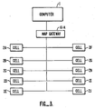
- FIG 4 shows how the system interrelates to the various cells in a factory.
- Cells are the basic units of autonomous operation in a factory.
- each of the cells 2A to 2J in the factory interrelate through a network using a MAP protocol.
- the cells 2A to 2J could each be robots or they could be other types of automated equipment.
- the nature of each of the cells is not important to an understanding of the invention, and they will not be described further.
- the computer 1 can be connected to the various cells through a LAN interface 1G and a MAP Gateway 1G-A. Thus, the computer 1 can communicate with each of the cells using the MAP protocol. As shown in Figure 3, the computer 1 interrelates with the cells 2A to 2J in an operational environment, and the invention can be used in its monitoring capacity.
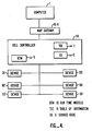
- the computer 1 can be connected to a single cell as shown in Figure 4.
- the invention can simulate the rest of the factory, and it can exercise the cell 2A as if the cell 2A were connected to the other machines in the network.
- the same tool used to design the system is thus used to test the individual components of the system and to monitor the system when it is finally operational.
- the engineering cycle of the system begins with initial concept, moves through the development and construction phases, becomes a diagnostic and maintenance activity when the system is finally operational, and eventually re-cycles when modification and upgrades are required.
- the cycle can be described as follows:
- this cycle is a sequential process, with early stages being completed before later stages are possible.
- Key to the invention is the ability to move freely through this cycle at will, maximizing the utilization of the engineer's creative insight.
- One aspect of the invention is the use of a captured representation of the system (RS) that is equivalent to the actual system (AS) - rather than a simulation of the actual system. This allows tests and modification on RS instead of AS, yet get accurate results.
- RS captured representation of the system
- AS actual system
- RS is the representation of the system, that is, the design specification of a system expressed in a form suitable for visual presentation on a work station terminal display.
- AS is the equivalent automatically rewritten in source code at the work station, which can be compiled or interpreted for direct use by the autonomous remote cells with a runtime module.
- AS is executable code and associated tables of values which can operate with a generic runtime module.
- AS and RS are equivalent, because AS is generated directly from RS by an automated process.
- pressing a button in the RS environment can "create” the AS version or any selected portion of it, by “downloading” a translation of the RS version that can be executed by a programmable processor in the AS environment.
- FIG 4 shows how a representative cell is organized.
- the cell includes a cell controller CC and a number of devices D1 to D7 which are controlled by the cell controller.
- the cell controller includes a Run Time Module (RTM) cc-3.
- RTM Run Time Module
- This RTM manages the execution of the system description that can be sent to it, and it interprets the Grafcet structural information in order to control the sequencing of the programs that actually send commands to the devices D1 to D7.
- the RTM also acts as the interface with computer 1 to upload a state of the controller and the devices.
- the computer 1 sends controller CC a Table of Information (TOI) cc-1 that represents the Grafcet structural information and other information such as breakpoint information and variable values.
- TOI Table of Information
- the computer 1 also sends cell controller CC programming source code cc-2. This code is compiled under control of the Run Time Module cc-3 to generate the control programs for the devices D1 to D7.
- Figure 5 shows a representative screen which appears on display 1A.
- the screen has the following areas which facilitate communication with the operator.
- Area 21 is a basic system interface for accessing computer files and processes.
- Area 22 is the interface to the MAP network.
- Area 23 is a the menu of items for interacting with the map network.
- Area 24 is a communication diagram drawn by the system to show how individual functional elements relate to each other.
- Area 25 is a trace window that displays message traffic between functional elements during operation or simulation.
- Area 26 is a window that displays the values of selected variables in simulated or operational mode.
- Area 27 is an animated depiction of the system's functional characteristics.
- Area 28 is a hierarchical diagram of a selected functional element.
- Area 29 is a window that displays a C language function within a functional element.
- Area 30 is the menu of high level activities that the user may select.
- Area 31 is a user interface to the underlying operating system that runs on the work station.
- Area 32 is a Grafcet program representing one
- the programming in computer 1 is an object-type of programming. Such programming, while different from conventional programming, is well known and is described in various textbooks. Object-oriented programming is not described by usual flow diagrams. Rather, it is described by diagrams such as Figure 6. The objects and their interrelationship are shown in Figure 6. The following is a description of the principal objects that comprise the embodiment of the invention shown herein. Item names are the objects found on the hierarchical diagram.
- Program 102 A program for executable specification of a program. Programs may be written by the user. Certain programs are provided in libraries as part of the system. Programs may contain other programs as subparts.
- Grafcetprogram 109 A specification of control flow written in the Grafcet language. It is made up of GrafcetObjects.
- Otherprogram 110 A language-independent program or fragment (expression) used to specify low-level actions, Boolean conditions, etc. It is primarily used with GrafcetPrograms, but it is also used in other places where it is appropriate for the user to specify custom behavior (e.g., MMI).
- MMI custom behavior
- the two languages supported in the specific embodiment are C and LISP. (These subclasses are completely interchangeable: the user can choose whichever is best suited to a particular situation.)
- GrafcetObject 103 The pieces from which Grafcet "flowcharts" are assembled.
- GrafcetStep 111 A "node” is a Grafcet “flowchart” that is activated when control passes to it and is deactivated when control passes out. Control passes as a result of a change in value of a GrafcetTransition 112. A GrafcetStep that is displayed on the screen while a simulation is running will be highlighted when it is activated.
- GrafcetRegularStep 145 A GrafcetStep that contains up to three OtherPrograms that specify the actions taken i) when the step is activated, ii) continuously while the step is active, and iii) when the step is deactivated, respectively.
- GrafcetMacroStep 146 A GrafcetStep that contains another Grafcet "flowchart" (a GrafcetMacroProgram).
- GrafcetMMFSStep 147 A library GrafcetStep for specifying MMFS message templates and send and receive behavior.
- GrafcetReceiptStep A GrafcetStep that contains MMFSReceiveTemplates for MMFSMessages to be received on some specified connection(s). When a message is received and a matching template is found, parameters are stored and actions taken according to specifications in the template.
- GrafcetSendStep 164 A GrafcetStep that contains MMFSSendTemplates and specifications for building and sending MMFSMessages.
- GrafcetTransition An object which connects two or more GrafcetSteps and specifies a boolean condition (an OtherProgram expression). The value of the boolean condition determines when control can pass from the preceding GrafcetStep(s) through the transition to the succeeding GrafcetStep(s) in the Grafcet "flowchart".
- GrafcetLink 113 A connector between GrafcetSteps and GrafcetTransitions.
- Various types of links indicate one-to-one connections, or synchronous or asynchronous parallel splits or joins.
- Folder 104 A collection of objects of a similar type. Some are permanent parts of the user's program (e.g., MMFSTemplateeFolder), while others are temporarily created by the system to display various information (e.g., MessageTraceFolder, AnalysisFolder). Folders are displayed and their contents manipulated by FolderBrowsers.
- MMFSTemplateeFolder Some are permanent parts of the user's program (e.g., MMFSTemplateeFolder), while others are temporarily created by the system to display various information (e.g., MessageTraceFolder, AnalysisFolder). Folders are displayed and their contents manipulated by FolderBrowsers.
- ModuleFolder 114 The top level user interface for manipulating modules ("main programs ⁇ created on the system) as a whole. Provides the capability to create, delete, copy, rename, compile, load and save modules, and to invoke various other types of Browsers on them.
- MMFSTemplateFolder 115 Contains user-specified templates for sending or receiving MMFSMessages.
- MessageTraceFolder 116 Contains network messages sent and/or received on specified connections or groups of connections.
- StateVariableFolder 117 Contains lists of user variables and their current values.
- NetworkConnectionFolder 118 Contains user specified parameters describing network connections.
- AnalysisFolder 166 Contains lists of objects derived from analysis of the user's program in response to queries regarding the location of reference to variables, calls to functions, etc.
- TransmissionMessage 119 A message to be sent on, or received from, a communications network or device.
- MAP Manufacturing Automation Protocol
- IMS Maxitron
- a TransmissionMessage contains information pertinent to transmission on a particular type of network (e.g., source and destination addresses), and an ApplicationMessage.
- ApplicationMessage 110 An application-level message with data (contents) formatted according to some application protocol (e.g., MMFS, MMS). Any application level protocol can be used with any type of network by using the appropriate combination of TransmissionMessage and ApplicationMessage.
- application protocol e.g., MMFS, MMS.
- Browser 106 A screen window that provides the user with an interface to an object and some Context operating on that object.
- the same type of Browser may apply to multiple types of Contexts of objects (e.g. SimulationBrowser).
- FormEditor 121 General purpose editor for viewing and editing fields of structured objects such as message templates, connection parameters, profile information.
- GrafcetProgramEditor 124 Graphical editor for Grafcet "flowcharts”. Allows GrafcetSteps, GrafcetTransitions and GrafcetLinks to be added, deleted, copied, renamed, zoomed, etc.
- GrafcetStructureBrowser 125 Displays the hierarchical structure of one or more Grafcet Programs.
- SimulationBrowser 126 Monitoring and control interface to the (local) simulation or (remote) execution of a Grafcetprogram. Allows the user to start, stop or single step the program, set breakpoints, display variable values, etc.
- AnimationBrowser 127 Displays a running animation of factory devices.
- AnimationEditor 124 Allows the user to create and edit animations of factory devices.
- MMIBrowser 129 Man-Machine Interface "Control console" interface to programs.
- MMIScreenEditor 130 Allows the user to create and edit MMI screens and establish their interaction with a Program.
- ManualMessageBrowser 131 Allows the user to manually establish and break network connections, and send, receive and trace messages to and from remote devices and processes.
- Context 107 A set of related operations that can be performed on an object, such as editing, simulation and analysis. The capabilities of a Context are presented to the user via a Browser.
- LocalGrafcetSimulationContext 156 The "execution engine” for running programs locally. Consists of a Grafcet interpreter and facilities for handling breakpoints, starting, stopping, stepping and displaying real time status of programs.
- RemoteGrafcetExecutionContext 157 The "execution engine” for running programs remotely. Exchanges command and monitoring information between a SimulationBrowser and an execution engine running on a remote machine. (In Figure 5 this is shown as cc-3.)
- Network 108 Provides a consistent interface to a physical communication network, or simulates such a network for internal connections.
Landscapes
- Engineering & Computer Science (AREA)
- Physics & Mathematics (AREA)
- Theoretical Computer Science (AREA)
- General Physics & Mathematics (AREA)
- Geometry (AREA)
- General Engineering & Computer Science (AREA)
- Computer Hardware Design (AREA)
- Evolutionary Computation (AREA)
- Mathematical Optimization (AREA)
- Data Mining & Analysis (AREA)
- Computational Mathematics (AREA)
- Pure & Applied Mathematics (AREA)
- Structural Engineering (AREA)
- Civil Engineering (AREA)
- Architecture (AREA)
- Mathematical Analysis (AREA)
- Databases & Information Systems (AREA)
- Mathematical Physics (AREA)
- Software Systems (AREA)
- Stored Programmes (AREA)
- Debugging And Monitoring (AREA)
- Testing And Monitoring For Control Systems (AREA)
- Management, Administration, Business Operations System, And Electronic Commerce (AREA)
Applications Claiming Priority (2)
| Application Number | Priority Date | Filing Date | Title |
|---|---|---|---|
| US11547387A | 1987-11-02 | 1987-11-02 | |
| US115473 | 1987-11-02 |
Publications (2)
| Publication Number | Publication Date |
|---|---|
| EP0315002A2 true EP0315002A2 (de) | 1989-05-10 |
| EP0315002A3 EP0315002A3 (de) | 1991-05-29 |
Family
ID=22361636
Family Applications (1)
| Application Number | Title | Priority Date | Filing Date |
|---|---|---|---|
| EP19880117647 Withdrawn EP0315002A3 (de) | 1987-11-02 | 1988-10-23 | Entwurfsystem unter Verwendung von visueller Sprache |
Country Status (4)
| Country | Link |
|---|---|
| EP (1) | EP0315002A3 (de) |
| JP (1) | JPH0214371A (de) |
| KR (1) | KR890008714A (de) |
| CA (1) | CA1298915C (de) |
Cited By (5)
| Publication number | Priority date | Publication date | Assignee | Title |
|---|---|---|---|---|
| GB2244360A (en) * | 1990-05-25 | 1991-11-27 | Microsys Consultants Limited | Security systems |
| GB2247597A (en) * | 1990-08-31 | 1992-03-04 | Canon Res Ct Europe Ltd | Image processing sequences |
| EP0415637A3 (en) * | 1989-08-30 | 1992-11-19 | Industrial Technology Institute | Method and apparatus for simulating a factory system |
| WO1997003389A1 (de) * | 1995-07-11 | 1997-01-30 | Elin Energieanwendung Gmbh | Verfahren zur erstellung eines anwenderspezifischen funktionsplanes für speicherprogrammierbare steuerungen (sps) |
| EP0718727A3 (de) * | 1994-12-21 | 1997-04-09 | Allen Bradley Co | Industrielle Steuerungen mit hochverteilter Verarbeitung und Verfahren zu deren Programmierung |
Family Cites Families (1)
| Publication number | Priority date | Publication date | Assignee | Title |
|---|---|---|---|---|
| EP0162670B1 (de) * | 1984-05-19 | 1991-01-02 | British Aerospace Public Limited Company | Industrielle Verarbeitungs- und Herstellungsverfahren |
-
1988
- 1988-10-23 EP EP19880117647 patent/EP0315002A3/de not_active Withdrawn
- 1988-10-28 KR KR1019880014090A patent/KR890008714A/ko not_active Withdrawn
- 1988-11-01 CA CA000581913A patent/CA1298915C/en not_active Expired - Lifetime
- 1988-11-02 JP JP63276352A patent/JPH0214371A/ja active Pending
Cited By (7)
| Publication number | Priority date | Publication date | Assignee | Title |
|---|---|---|---|---|
| EP0415637A3 (en) * | 1989-08-30 | 1992-11-19 | Industrial Technology Institute | Method and apparatus for simulating a factory system |
| GB2244360A (en) * | 1990-05-25 | 1991-11-27 | Microsys Consultants Limited | Security systems |
| GB2247597A (en) * | 1990-08-31 | 1992-03-04 | Canon Res Ct Europe Ltd | Image processing sequences |
| GB2247597B (en) * | 1990-08-31 | 1995-03-08 | Canon Res Ct Europe Ltd | Image processing |
| US5631974A (en) * | 1990-08-31 | 1997-05-20 | Canon Research Centre Europe, Ltd. | Image processing |
| EP0718727A3 (de) * | 1994-12-21 | 1997-04-09 | Allen Bradley Co | Industrielle Steuerungen mit hochverteilter Verarbeitung und Verfahren zu deren Programmierung |
| WO1997003389A1 (de) * | 1995-07-11 | 1997-01-30 | Elin Energieanwendung Gmbh | Verfahren zur erstellung eines anwenderspezifischen funktionsplanes für speicherprogrammierbare steuerungen (sps) |
Also Published As
| Publication number | Publication date |
|---|---|
| KR890008714A (ko) | 1989-07-12 |
| EP0315002A3 (de) | 1991-05-29 |
| JPH0214371A (ja) | 1990-01-18 |
| CA1298915C (en) | 1992-04-14 |
Similar Documents
| Publication | Publication Date | Title |
|---|---|---|
| KR100735949B1 (ko) | 설비, 특히 역사설비에 명령을 하는 철도의 논리소프트웨어 엔진들을 점검하는 장치와 방법 | |
| CN109814478B (zh) | 基于iOpenWorks的虚拟调试系统 | |
| US6643555B1 (en) | Method and apparatus for generating an application for an automation control system | |
| EP0869433A2 (de) | Ein Prüfungsentwicklungssystem und -verfahren für Software mit einer grafischen Benutzerschnittstelle | |
| US4914567A (en) | Design system using visual language | |
| CN101872280A (zh) | 在过程控制系统中为操作员界面显示配置动画和事件 | |
| US20120117537A1 (en) | Flow Chart Programming Platform for Testers and Simulators | |
| Bee | PLC and HMI development with Siemens TIA portal | |
| CN113885426A (zh) | 一种挖掘机控制程序plc代码自动生成方法、测试方法及可视化测试系统 | |
| CN114925516A (zh) | 一种自动建模并仿真的方法和装置 | |
| CA1298915C (en) | Design system using visual language | |
| JP2000112737A (ja) | プログラム作成装置 | |
| EP4455869A1 (de) | Arbeitsflusskonstruktionsverfahren und -system, medium und programmprodukt | |
| Fält et al. | Emulation of a production cell-Developing a virtual commissioning model in a concurrent environment | |
| CN112764858A (zh) | 一种机器视觉交互系统及其运行方法 | |
| Edan et al. | Transfer of software engineering tools from information systems to production systems | |
| Didic et al. | McCIM: execution of CIMOSA Models | |
| Flanagan | Using VR to Validate and Visualize MBSE‐Designed Interfaces | |
| Sorvala | ASSESSMENT AND IMPLEMENTATION OF AN AUTOMATIC DEPLOYMENT TOOL FOR INDUSTRIAL AUTOMATION APPLICATIONS | |
| Giménez et al. | Realizing real-time digital twins for industrial cobots | |
| Harrington et al. | A Portable Process-Oriented Compiler for Event Driven Simulation | |
| Jarque Pérez | Set up and control of a UR3 Robot using ROS2 Humble | |
| Bührer | Subject-Oriented Reference Model for Virtual Factory Operations Commissioning | |
| Kanev et al. | A framework for graphically-oriented human computer interactions in intelligent operator support systems | |
| Alexopoulos et al. | A Model-Based Approach to Automated Digital Twin Generation in Manufacturing |
Legal Events
| Date | Code | Title | Description |
|---|---|---|---|
| PUAI | Public reference made under article 153(3) epc to a published international application that has entered the european phase |
Free format text: ORIGINAL CODE: 0009012 |
|
| AK | Designated contracting states |
Kind code of ref document: A2 Designated state(s): CH DE FR GB IT LI SE |
|
| PUAL | Search report despatched |
Free format text: ORIGINAL CODE: 0009013 |
|
| AK | Designated contracting states |
Kind code of ref document: A3 Designated state(s): CH DE FR GB IT LI SE |
|
| 17P | Request for examination filed |
Effective date: 19910720 |
|
| RAP3 | Party data changed (applicant data changed or rights of an application transferred) |
Owner name: FLEXIS CONTROL INCORPORATED |
|
| STAA | Information on the status of an ep patent application or granted ep patent |
Free format text: STATUS: THE APPLICATION IS DEEMED TO BE WITHDRAWN |
|
| 18D | Application deemed to be withdrawn |
Effective date: 19940503 |