EP0315047A2 - Support de catalyseur monolithique - Google Patents
Support de catalyseur monolithique Download PDFInfo
- Publication number
- EP0315047A2 EP0315047A2 EP88117891A EP88117891A EP0315047A2 EP 0315047 A2 EP0315047 A2 EP 0315047A2 EP 88117891 A EP88117891 A EP 88117891A EP 88117891 A EP88117891 A EP 88117891A EP 0315047 A2 EP0315047 A2 EP 0315047A2
- Authority
- EP
- European Patent Office
- Prior art keywords
- channel
- channels
- monolithic catalyst
- openings
- another
- Prior art date
- Legal status (The legal status is an assumption and is not a legal conclusion. Google has not performed a legal analysis and makes no representation as to the accuracy of the status listed.)
- Granted
Links
Images
Classifications
-
- F—MECHANICAL ENGINEERING; LIGHTING; HEATING; WEAPONS; BLASTING
- F01—MACHINES OR ENGINES IN GENERAL; ENGINE PLANTS IN GENERAL; STEAM ENGINES
- F01N—GAS-FLOW SILENCERS OR EXHAUST APPARATUS FOR MACHINES OR ENGINES IN GENERAL; GAS-FLOW SILENCERS OR EXHAUST APPARATUS FOR INTERNAL-COMBUSTION ENGINES
- F01N3/00—Exhaust or silencing apparatus having means for purifying, rendering innocuous, or otherwise treating exhaust
- F01N3/08—Exhaust or silencing apparatus having means for purifying, rendering innocuous, or otherwise treating exhaust for rendering innocuous
- F01N3/10—Exhaust or silencing apparatus having means for purifying, rendering innocuous, or otherwise treating exhaust for rendering innocuous by thermal or catalytic conversion of noxious components of exhaust
- F01N3/24—Exhaust or silencing apparatus having means for purifying, rendering innocuous, or otherwise treating exhaust for rendering innocuous by thermal or catalytic conversion of noxious components of exhaust characterised by constructional aspects of converting apparatus
- F01N3/28—Construction of catalytic reactors
- F01N3/2803—Construction of catalytic reactors characterised by structure, by material or by manufacturing of catalyst support
- F01N3/2807—Metal other than sintered metal
- F01N3/281—Metallic honeycomb monoliths made of stacked or rolled sheets, foils or plates
- F01N3/2817—Metallic honeycomb monoliths made of stacked or rolled sheets, foils or plates only with non-corrugated sheets, plates or foils
-
- B—PERFORMING OPERATIONS; TRANSPORTING
- B01—PHYSICAL OR CHEMICAL PROCESSES OR APPARATUS IN GENERAL
- B01J—CHEMICAL OR PHYSICAL PROCESSES, e.g. CATALYSIS OR COLLOID CHEMISTRY; THEIR RELEVANT APPARATUS
- B01J35/00—Catalysts, in general, characterised by their form or physical properties
- B01J35/50—Catalysts, in general, characterised by their form or physical properties characterised by their shape or configuration
- B01J35/56—Foraminous structures having flow-through passages or channels, e.g. grids or three-dimensional [3D] monoliths
- B01J35/57—Honeycombs
-
- F—MECHANICAL ENGINEERING; LIGHTING; HEATING; WEAPONS; BLASTING
- F01—MACHINES OR ENGINES IN GENERAL; ENGINE PLANTS IN GENERAL; STEAM ENGINES
- F01N—GAS-FLOW SILENCERS OR EXHAUST APPARATUS FOR MACHINES OR ENGINES IN GENERAL; GAS-FLOW SILENCERS OR EXHAUST APPARATUS FOR INTERNAL-COMBUSTION ENGINES
- F01N3/00—Exhaust or silencing apparatus having means for purifying, rendering innocuous, or otherwise treating exhaust
- F01N3/08—Exhaust or silencing apparatus having means for purifying, rendering innocuous, or otherwise treating exhaust for rendering innocuous
- F01N3/10—Exhaust or silencing apparatus having means for purifying, rendering innocuous, or otherwise treating exhaust for rendering innocuous by thermal or catalytic conversion of noxious components of exhaust
- F01N3/24—Exhaust or silencing apparatus having means for purifying, rendering innocuous, or otherwise treating exhaust for rendering innocuous by thermal or catalytic conversion of noxious components of exhaust characterised by constructional aspects of converting apparatus
- F01N3/28—Construction of catalytic reactors
- F01N3/2803—Construction of catalytic reactors characterised by structure, by material or by manufacturing of catalyst support
- F01N3/2807—Metal other than sintered metal
- F01N3/281—Metallic honeycomb monoliths made of stacked or rolled sheets, foils or plates
-
- F—MECHANICAL ENGINEERING; LIGHTING; HEATING; WEAPONS; BLASTING
- F01—MACHINES OR ENGINES IN GENERAL; ENGINE PLANTS IN GENERAL; STEAM ENGINES
- F01N—GAS-FLOW SILENCERS OR EXHAUST APPARATUS FOR MACHINES OR ENGINES IN GENERAL; GAS-FLOW SILENCERS OR EXHAUST APPARATUS FOR INTERNAL-COMBUSTION ENGINES
- F01N3/00—Exhaust or silencing apparatus having means for purifying, rendering innocuous, or otherwise treating exhaust
- F01N3/08—Exhaust or silencing apparatus having means for purifying, rendering innocuous, or otherwise treating exhaust for rendering innocuous
- F01N3/10—Exhaust or silencing apparatus having means for purifying, rendering innocuous, or otherwise treating exhaust for rendering innocuous by thermal or catalytic conversion of noxious components of exhaust
- F01N3/24—Exhaust or silencing apparatus having means for purifying, rendering innocuous, or otherwise treating exhaust for rendering innocuous by thermal or catalytic conversion of noxious components of exhaust characterised by constructional aspects of converting apparatus
- F01N3/28—Construction of catalytic reactors
- F01N3/2803—Construction of catalytic reactors characterised by structure, by material or by manufacturing of catalyst support
- F01N3/2825—Ceramics
- F01N3/2828—Ceramic multi-channel monoliths, e.g. honeycombs
-
- F—MECHANICAL ENGINEERING; LIGHTING; HEATING; WEAPONS; BLASTING
- F01—MACHINES OR ENGINES IN GENERAL; ENGINE PLANTS IN GENERAL; STEAM ENGINES
- F01N—GAS-FLOW SILENCERS OR EXHAUST APPARATUS FOR MACHINES OR ENGINES IN GENERAL; GAS-FLOW SILENCERS OR EXHAUST APPARATUS FOR INTERNAL-COMBUSTION ENGINES
- F01N2330/00—Structure of catalyst support or particle filter
- F01N2330/02—Metallic plates or honeycombs, e.g. superposed or rolled-up corrugated or otherwise deformed sheet metal
-
- F—MECHANICAL ENGINEERING; LIGHTING; HEATING; WEAPONS; BLASTING
- F01—MACHINES OR ENGINES IN GENERAL; ENGINE PLANTS IN GENERAL; STEAM ENGINES
- F01N—GAS-FLOW SILENCERS OR EXHAUST APPARATUS FOR MACHINES OR ENGINES IN GENERAL; GAS-FLOW SILENCERS OR EXHAUST APPARATUS FOR INTERNAL-COMBUSTION ENGINES
- F01N2330/00—Structure of catalyst support or particle filter
- F01N2330/06—Ceramic, e.g. monoliths
-
- F—MECHANICAL ENGINEERING; LIGHTING; HEATING; WEAPONS; BLASTING
- F01—MACHINES OR ENGINES IN GENERAL; ENGINE PLANTS IN GENERAL; STEAM ENGINES
- F01N—GAS-FLOW SILENCERS OR EXHAUST APPARATUS FOR MACHINES OR ENGINES IN GENERAL; GAS-FLOW SILENCERS OR EXHAUST APPARATUS FOR INTERNAL-COMBUSTION ENGINES
- F01N2330/00—Structure of catalyst support or particle filter
- F01N2330/30—Honeycomb supports characterised by their structural details
- F01N2330/34—Honeycomb supports characterised by their structural details with flow channels of polygonal cross section
-
- F—MECHANICAL ENGINEERING; LIGHTING; HEATING; WEAPONS; BLASTING
- F01—MACHINES OR ENGINES IN GENERAL; ENGINE PLANTS IN GENERAL; STEAM ENGINES
- F01N—GAS-FLOW SILENCERS OR EXHAUST APPARATUS FOR MACHINES OR ENGINES IN GENERAL; GAS-FLOW SILENCERS OR EXHAUST APPARATUS FOR INTERNAL-COMBUSTION ENGINES
- F01N2330/00—Structure of catalyst support or particle filter
- F01N2330/30—Honeycomb supports characterised by their structural details
- F01N2330/36—Honeycomb supports characterised by their structural details with flow channels formed by tubes
Definitions
- the present invention relates to catalysts in the form of monolithic bodies which are penetrated by a multiplicity of channels which are parallel to one another and which are separated from one another by wall webs.
- Such catalysts which have also become known as honeycomb catalysts, are used primarily where a low pressure drop is important. This low pressure drop is particularly important for the conversion of substances that are present in small proportions, for example in the conversion of pollutants contained in exhaust gases such as nitrogen oxides, carbon monoxide and unburned hydrocarbons.
- exhaust gases are under only a slight excess pressure and it is therefore not possible to use catalyst beds in the treatment of such gases, since they oppose the passage of gas with too great a resistance.
- the use of catalyst beds is also forbidden in the treatment of dust-containing gases, since the gas passages are more or less quickly blocked by dust deposits in the bed and oppose increasing resistance to the gas passage.
- the catalytically active mass e.g., on a prefabricated honeycomb carrier made of metal or ceramic material, can be used. by impregnation or coating, apply or full catalysts are produced directly, i.e. Catalysts that consist exclusively of the catalytically active mass.
- Honeycomb carriers made of ceramic or of full catalysts are usually produced by extrusion (cf. Advanced Materials in Catalysis, Academic Press, 1977, pages 293 to 322).
- a powdery mixture of the ceramic oxides and / or catalytically active oxides is processed in the presence of plasticizers and liquid by kneading to a plastic mass and this is extruded into a honeycomb body.
- the latter is dried, calcined and, if not previously done, coated with catalytically active material.
- honeycomb bodies produced in this way usually have lengths of 0.1 to 1.5 m and cross-sectional widths of 0.03 to 1 m (in the case of honeycomb bodies with a circular cross section: diameter).
- DE-AS-26 58 539 describes a process for the selective removal of nitrogen oxides by reduction with ammonia in the presence of honeycomb-shaped catalysts.
- the hydraulic diameter of the channels of the honeycomb catalysts should be 2.0 to 30 mm, the open frontal area 50 to 80%, and the exhaust gas velocity - in the channels - 0.5 to 60 m / sec. This is to prevent the catalyst passages from becoming blocked by dust deposits, while at the same time the mechanical stability of the catalyst bodies meets the requirements set in practice.
- DE-OS 34 42 929 and DE-OS 34 44 439 which are in an additional relationship to this, propose catalysts which are arranged in a housing, are flowed around on all sides and have longitudinal and transverse channels in the direction of flow. This arrangement is intended to achieve intimate contacting and cleaning. How these transverse and longitudinal channels are arranged and how they are connected to one another, however, cannot be found in these published documents.
- the present invention was based on the object of providing monolithic catalyst bodies which, in the direction of their main axis, are interspersed with a plurality of channels which are parallel to one another and are separated from one another by wall webs and which ensure an increased conversion compared to known monolithic catalyst bodies under otherwise comparable conditions.
- the present invention is based on the surprising finding that the effectiveness of a monolithic catalyst interspersed with channels can be increased under given conditions if the channels are not separated from one another from the inflow surface to the outflow surface with continuous wall webs, but that at certain intervals the depend on the hydraulic diameter of a channel, there are communication options between at least two adjacent channels, ie that the wall webs have openings at certain intervals through which a gas exchange can take place between the individual channels.
- the hydraulic diameter D is defined as The hydraulic diameter of a channel is usually from 0.1 to 1.2 cm.
- the openings can be made on the finished catalyst body, for example by piercing and drilling.
- the holes are placed in such a way that as few holes as possible can be used.
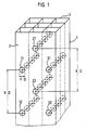
- FIG. 1 shows a monolithic catalyst body with 3 ⁇ 3 honeycomb channels with a square cross section.
- the catalyst body has through-holes 11 and 12, 21 and 22 and 31 and 32, which are placed so that they extend from one lateral surface 2 to the opposite lateral surface 3, so that the channels lying one behind the other at the same height through openings communicate with each other in the wall bridges.
- the bore groups 11 and 12, 21 and 22 as well as 31 and 32 are expediently not at a height, but are, as illustrated in the figure, offset from one another, for example at a gap, around in this way impair the mechanical stability of the catalyst body as little as possible.
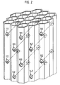
- FIG. 2 shows a monolithic catalyst body with through channels with the cross-sectional area of an equilateral hexagon.
- the honeycomb body is provided with 5 groups (111/112, 121/122, 131/132, 141/142 and 151/152) of bores which extend from one boundary surface to the other boundary surface.
- honeycomb bodies made of aluminum oxide, which are interspersed with 3 x 3 channels (hydraulic diameter of a channel 6 mm, wall thickness of the webs separating the channels from each other 1.4 mm), are drilled.
- holes are made at a distance of 30 mm between the holes of a group of tube holes with hole diameters of 3 mm, the first hole 11 or 31 of the hole groups 11 and 12 and 31 and 32 being at a distance of 10 mm each from the inflow surface and the first bore 21 of the borehole group 21 and 22 are at a distance of 25 mm from the inflow surface.
- bores are provided at a distance of 15 mm between the bores of a group of boreholes, the distance of the first boreholes 11 and 31 from the inflow surface likewise being 10 mm, and that of the first borehole 21 being 17.5 mm from the inflow surface .
- honeycomb bodies are charged with 10% by weight of V2O5- as a catalytically active component.
- a gas consisting of 200 vol.ppm NO, 4 vol.% Oxygen, 10 vol.% Water vapor, the rest nitrogen is applied to the honeycomb-shaped catalysts. Ammonia is added to this gas stream in such an amount that the molar ratio NH 3: NO is 1.2.
- the activity of the monolithic catalyst is increased by 10 to 20%, depending on the number of holes, compared to a monolithic comparison catalyst without holes.
Landscapes
- Chemical & Material Sciences (AREA)
- Engineering & Computer Science (AREA)
- Chemical Kinetics & Catalysis (AREA)
- Health & Medical Sciences (AREA)
- Toxicology (AREA)
- Combustion & Propulsion (AREA)
- Mechanical Engineering (AREA)
- General Engineering & Computer Science (AREA)
- Materials Engineering (AREA)
- Organic Chemistry (AREA)
- Ceramic Engineering (AREA)
- Catalysts (AREA)
Applications Claiming Priority (2)
| Application Number | Priority Date | Filing Date | Title |
|---|---|---|---|
| DE19873737248 DE3737248A1 (de) | 1987-11-03 | 1987-11-03 | Monolithischer katalysatorkoerper |
| DE3737248 | 1987-11-03 |
Publications (3)
| Publication Number | Publication Date |
|---|---|
| EP0315047A2 true EP0315047A2 (fr) | 1989-05-10 |
| EP0315047A3 EP0315047A3 (en) | 1989-09-20 |
| EP0315047B1 EP0315047B1 (fr) | 1991-06-05 |
Family
ID=6339671
Family Applications (1)
| Application Number | Title | Priority Date | Filing Date |
|---|---|---|---|
| EP88117891A Expired - Lifetime EP0315047B1 (fr) | 1987-11-03 | 1988-10-27 | Support de catalyseur monolithique |
Country Status (2)
| Country | Link |
|---|---|
| EP (1) | EP0315047B1 (fr) |
| DE (2) | DE3737248A1 (fr) |
Cited By (5)
| Publication number | Priority date | Publication date | Assignee | Title |
|---|---|---|---|---|
| US5118868A (en) * | 1989-10-16 | 1992-06-02 | Haldor Topsoe A/S | Catalyst for preparing aldehyde |
| WO1999029425A1 (fr) * | 1997-12-05 | 1999-06-17 | Valeriy Ivanovich Chernishev | Element catalytique servant a la transformation de l'ammoniac |
| WO2000073046A1 (fr) * | 1999-05-31 | 2000-12-07 | Emitec Gesellschaft Für Emissionstechnologie Mbh | Corps alveolaire ceramique a insert |
| FR2823139A1 (fr) * | 2001-04-05 | 2002-10-11 | Inst Francais Du Petrole | Support de catalyseur avec des reseaux de canaux secants, reacteur de catalyse comprenant un tel support et procede pour realiser un tel support de catalyseur |
| WO2014071424A1 (fr) * | 2012-11-08 | 2014-05-15 | Ibiden Porzellanfabrik Frauenthal Gmbh | Corps alvéolaire en matériau céramique |
Families Citing this family (1)
| Publication number | Priority date | Publication date | Assignee | Title |
|---|---|---|---|---|
| SE470546B (sv) * | 1992-12-15 | 1994-08-01 | Sandvik Ab | Katalysatorenhet för behandling av avgaser från förbränningsmotor samt sätt för tillverkning av katalysatorenheten |
Family Cites Families (2)
| Publication number | Priority date | Publication date | Assignee | Title |
|---|---|---|---|---|
| JPS59186621A (ja) * | 1983-04-05 | 1984-10-23 | Ngk Insulators Ltd | 多孔体 |
| DE3341868A1 (de) * | 1983-11-19 | 1985-05-30 | Süddeutsche Kühlerfabrik Julius Fr. Behr GmbH & Co KG, 7000 Stuttgart | Matrix fuer einen katalytischen reaktor |
-
1987
- 1987-11-03 DE DE19873737248 patent/DE3737248A1/de not_active Withdrawn
-
1988
- 1988-10-27 EP EP88117891A patent/EP0315047B1/fr not_active Expired - Lifetime
- 1988-10-27 DE DE8888117891T patent/DE3863165D1/de not_active Expired - Lifetime
Cited By (10)
| Publication number | Priority date | Publication date | Assignee | Title |
|---|---|---|---|---|
| US5118868A (en) * | 1989-10-16 | 1992-06-02 | Haldor Topsoe A/S | Catalyst for preparing aldehyde |
| WO1999029425A1 (fr) * | 1997-12-05 | 1999-06-17 | Valeriy Ivanovich Chernishev | Element catalytique servant a la transformation de l'ammoniac |
| WO2000073046A1 (fr) * | 1999-05-31 | 2000-12-07 | Emitec Gesellschaft Für Emissionstechnologie Mbh | Corps alveolaire ceramique a insert |
| JP2003500256A (ja) * | 1999-05-31 | 2003-01-07 | エミテク・ゲゼルシャフト・フュール・エミシオーンテクノロギー・ミット・ベシュレンクテル・ハフツング | 挿入物を備えるセラミックハニカム体 |
| RU2238186C2 (ru) * | 1999-05-31 | 2004-10-20 | Эмитек Гезельшафт Фюр Эмиссионстехнологи Мбх | Керамический сотовый элемент со вставками |
| FR2823139A1 (fr) * | 2001-04-05 | 2002-10-11 | Inst Francais Du Petrole | Support de catalyseur avec des reseaux de canaux secants, reacteur de catalyse comprenant un tel support et procede pour realiser un tel support de catalyseur |
| WO2002081083A1 (fr) * | 2001-04-05 | 2002-10-17 | Institut Francais Du Petrole | Support de catalyseur avec des reseaux de canaux scants, reacteur de catalyse comprenant un tel support et procede pour realiser un tel support de catalyseur |
| US7141530B2 (en) | 2001-04-05 | 2006-11-28 | Institut Francais Du Petrole | Catalyst support with intersecting channel network, catalysis reactor comprising same and method for making same |
| WO2014071424A1 (fr) * | 2012-11-08 | 2014-05-15 | Ibiden Porzellanfabrik Frauenthal Gmbh | Corps alvéolaire en matériau céramique |
| US9630135B2 (en) | 2012-11-08 | 2017-04-25 | Ibiden Porzellanfabrik Frauenthal Gmbh | Honeycomb body made of ceramic material |
Also Published As
| Publication number | Publication date |
|---|---|
| DE3863165D1 (de) | 1991-07-11 |
| DE3737248A1 (de) | 1989-05-18 |
| EP0315047B1 (fr) | 1991-06-05 |
| EP0315047A3 (en) | 1989-09-20 |
Similar Documents
| Publication | Publication Date | Title |
|---|---|---|
| EP0482145B1 (fr) | Dispositif catalyseur dans une colonne | |
| DE4042079C2 (de) | Abgasreinigungs-Katalysator zur Verwendung bei Verbrennungsmotoren und Verfahren zu seiner Herstellung | |
| EP0611594A1 (fr) | Catalyseur pour la conversion de réactants dans un mélange gazeux | |
| DE69534984T3 (de) | Katalytische Einheit und Abgasreinigungsvorrichtung | |
| EP0186801A2 (fr) | Matrice porteuse en particulier pour un réacteur catalytique pour la purification des gaz d'échappement | |
| DE3740289A1 (de) | Katalysator zur selektiven reduktion von stickoxiden mit ammoniak | |
| EP0542805B1 (fr) | Corps en nid d'abeilles ayant des canaux a sections transversales diverses, notamment corps de support de catalyseur | |
| EP0587074B1 (fr) | Dispositif pour mélanger et tourbillonner des gaz et des liquides, en particulier pour des supports des catalyseurs d'automobiles | |
| DE69515773T2 (de) | Monolitischer, poröser Träger für Filtrationsmembrane | |
| EP0315047B1 (fr) | Support de catalyseur monolithique | |
| DE3614347C2 (fr) | ||
| DE69701525T2 (de) | Katalysator für verbrennungsmotor mit verbrennung eines mageren gemisches | |
| DE2834358C3 (de) | Katalytischer Reaktor | |
| DE3430886C2 (fr) | ||
| DE19816482C2 (de) | Plattenkatalysator | |
| EP1636469B1 (fr) | Collecteur destine a un dispositif d'epuration de gaz d'echappement | |
| EP0577117A2 (fr) | Procédé pour la fabrication d'un catalyseur | |
| DE2649825C3 (de) | Vorrichtung zur katalytischen Reinigung von Verbrennungsmotorabgasen | |
| EP1032470B1 (fr) | Corps catalyseur | |
| DE10003090A1 (de) | Durchströmbare Katalysatoranordnung sowie Verwendung der Katalysatoranordnung | |
| DE69419911T2 (de) | Katalysatorsystem und ihre anwendung | |
| DE3501941A1 (de) | Steg-katalysator vorrichtung zur entfernung von stickoxiden | |
| EP0501138A1 (fr) | Filtre pour gaz à haute température, plus particulièrement filtre de suie d'un diesel | |
| EP1082172B1 (fr) | Module catalyseur | |
| DE8901773U1 (de) | Katalysator-Formkörper mit Abstandshaltern |
Legal Events
| Date | Code | Title | Description |
|---|---|---|---|
| PUAI | Public reference made under article 153(3) epc to a published international application that has entered the european phase |
Free format text: ORIGINAL CODE: 0009012 |
|
| AK | Designated contracting states |
Kind code of ref document: A2 Designated state(s): BE DE FR GB NL SE |
|
| PUAL | Search report despatched |
Free format text: ORIGINAL CODE: 0009013 |
|
| AK | Designated contracting states |
Kind code of ref document: A3 Designated state(s): BE DE FR GB NL SE |
|
| 17P | Request for examination filed |
Effective date: 19900113 |
|
| 17Q | First examination report despatched |
Effective date: 19900723 |
|
| GRAA | (expected) grant |
Free format text: ORIGINAL CODE: 0009210 |
|
| AK | Designated contracting states |
Kind code of ref document: B1 Designated state(s): BE DE FR GB NL SE |
|
| PG25 | Lapsed in a contracting state [announced via postgrant information from national office to epo] |
Ref country code: SE Effective date: 19910605 Ref country code: NL Effective date: 19910605 Ref country code: GB Effective date: 19910605 Ref country code: FR Effective date: 19910605 Ref country code: BE Effective date: 19910605 |
|
| REF | Corresponds to: |
Ref document number: 3863165 Country of ref document: DE Date of ref document: 19910711 |
|
| PGFP | Annual fee paid to national office [announced via postgrant information from national office to epo] |
Ref country code: DE Payment date: 19911018 Year of fee payment: 4 |
|
| EN | Fr: translation not filed | ||
| NLV1 | Nl: lapsed or annulled due to failure to fulfill the requirements of art. 29p and 29m of the patents act | ||
| GBV | Gb: ep patent (uk) treated as always having been void in accordance with gb section 77(7)/1977 [no translation filed] | ||
| PLBI | Opposition filed |
Free format text: ORIGINAL CODE: 0009260 |
|
| 26 | Opposition filed |
Effective date: 19920226 |
|
| RDAG | Patent revoked |
Free format text: ORIGINAL CODE: 0009271 |
|
| STAA | Information on the status of an ep patent application or granted ep patent |
Free format text: STATUS: PATENT REVOKED |
|
| 27W | Patent revoked |
Effective date: 19920905 |