EP0542805B1 - Corps en nid d'abeilles ayant des canaux a sections transversales diverses, notamment corps de support de catalyseur - Google Patents
Corps en nid d'abeilles ayant des canaux a sections transversales diverses, notamment corps de support de catalyseur Download PDFInfo
- Publication number
- EP0542805B1 EP0542805B1 EP91914048A EP91914048A EP0542805B1 EP 0542805 B1 EP0542805 B1 EP 0542805B1 EP 91914048 A EP91914048 A EP 91914048A EP 91914048 A EP91914048 A EP 91914048A EP 0542805 B1 EP0542805 B1 EP 0542805B1
- Authority
- EP
- European Patent Office
- Prior art keywords
- metal sheets
- channels
- honeycombed body
- body according
- cross
- Prior art date
- Legal status (The legal status is an assumption and is not a legal conclusion. Google has not performed a legal analysis and makes no representation as to the accuracy of the status listed.)
- Expired - Lifetime
Links
Images


Classifications
-
- F—MECHANICAL ENGINEERING; LIGHTING; HEATING; WEAPONS; BLASTING
- F01—MACHINES OR ENGINES IN GENERAL; ENGINE PLANTS IN GENERAL; STEAM ENGINES
- F01N—GAS-FLOW SILENCERS OR EXHAUST APPARATUS FOR MACHINES OR ENGINES IN GENERAL; GAS-FLOW SILENCERS OR EXHAUST APPARATUS FOR INTERNAL-COMBUSTION ENGINES
- F01N3/00—Exhaust or silencing apparatus having means for purifying, rendering innocuous, or otherwise treating exhaust
- F01N3/08—Exhaust or silencing apparatus having means for purifying, rendering innocuous, or otherwise treating exhaust for rendering innocuous
- F01N3/10—Exhaust or silencing apparatus having means for purifying, rendering innocuous, or otherwise treating exhaust for rendering innocuous by thermal or catalytic conversion of noxious components of exhaust
- F01N3/24—Exhaust or silencing apparatus having means for purifying, rendering innocuous, or otherwise treating exhaust for rendering innocuous by thermal or catalytic conversion of noxious components of exhaust characterised by constructional aspects of converting apparatus
- F01N3/28—Construction of catalytic reactors
- F01N3/2803—Construction of catalytic reactors characterised by structure, by material or by manufacturing of catalyst support
- F01N3/2807—Metal other than sintered metal
- F01N3/281—Metallic honeycomb monoliths made of stacked or rolled sheets, foils or plates
-
- B—PERFORMING OPERATIONS; TRANSPORTING
- B01—PHYSICAL OR CHEMICAL PROCESSES OR APPARATUS IN GENERAL
- B01J—CHEMICAL OR PHYSICAL PROCESSES, e.g. CATALYSIS OR COLLOID CHEMISTRY; THEIR RELEVANT APPARATUS
- B01J35/00—Catalysts, in general, characterised by their form or physical properties
- B01J35/50—Catalysts, in general, characterised by their form or physical properties characterised by their shape or configuration
- B01J35/56—Foraminous structures having flow-through passages or channels, e.g. grids or three-dimensional [3D] monoliths
- B01J35/57—Honeycombs
-
- F—MECHANICAL ENGINEERING; LIGHTING; HEATING; WEAPONS; BLASTING
- F01—MACHINES OR ENGINES IN GENERAL; ENGINE PLANTS IN GENERAL; STEAM ENGINES
- F01N—GAS-FLOW SILENCERS OR EXHAUST APPARATUS FOR MACHINES OR ENGINES IN GENERAL; GAS-FLOW SILENCERS OR EXHAUST APPARATUS FOR INTERNAL-COMBUSTION ENGINES
- F01N2330/00—Structure of catalyst support or particle filter
- F01N2330/02—Metallic plates or honeycombs, e.g. superposed or rolled-up corrugated or otherwise deformed sheet metal
-
- F—MECHANICAL ENGINEERING; LIGHTING; HEATING; WEAPONS; BLASTING
- F01—MACHINES OR ENGINES IN GENERAL; ENGINE PLANTS IN GENERAL; STEAM ENGINES
- F01N—GAS-FLOW SILENCERS OR EXHAUST APPARATUS FOR MACHINES OR ENGINES IN GENERAL; GAS-FLOW SILENCERS OR EXHAUST APPARATUS FOR INTERNAL-COMBUSTION ENGINES
- F01N2330/00—Structure of catalyst support or particle filter
- F01N2330/30—Honeycomb supports characterised by their structural details
- F01N2330/32—Honeycomb supports characterised by their structural details characterised by the shape, form or number of corrugations of plates, sheets or foils
- F01N2330/321—Honeycomb supports characterised by their structural details characterised by the shape, form or number of corrugations of plates, sheets or foils with two or more different kinds of corrugations in the same substrate
-
- Y—GENERAL TAGGING OF NEW TECHNOLOGICAL DEVELOPMENTS; GENERAL TAGGING OF CROSS-SECTIONAL TECHNOLOGIES SPANNING OVER SEVERAL SECTIONS OF THE IPC; TECHNICAL SUBJECTS COVERED BY FORMER USPC CROSS-REFERENCE ART COLLECTIONS [XRACs] AND DIGESTS
- Y02—TECHNOLOGIES OR APPLICATIONS FOR MITIGATION OR ADAPTATION AGAINST CLIMATE CHANGE
- Y02A—TECHNOLOGIES FOR ADAPTATION TO CLIMATE CHANGE
- Y02A50/00—TECHNOLOGIES FOR ADAPTATION TO CLIMATE CHANGE in human health protection, e.g. against extreme weather
- Y02A50/20—Air quality improvement or preservation, e.g. vehicle emission control or emission reduction by using catalytic converters
Definitions
- the present invention relates to a honeycomb body, in particular a catalyst carrier body for exhaust systems of internal combustion engines, with channels through which a fluid can flow in a flow direction and which is constructed from a multiplicity of individual sheets, at least some of which run approximately parallel to the flow direction to form the channels Has structures.
- honeycomb bodies are e.g. B. from EP-C-0 245 737 or from EP-C-0 245 738 known.
- a honeycomb body is also known from WO-90/03220, which is made up of at least three intertwined stacks of sheets.
- honeycomb body When using such a honeycomb body in a flowing fluid, it cannot always be ensured due to the geometry of a pipeline system that such a honeycomb body is flowed over uniformly over the entire cross-sectional area. This is a problem in particular in exhaust systems of motor vehicles, since there are no lengths and internals to equalize the flow.
- a honeycomb body may have a higher flow velocity in its central area than in its outer areas, resulting in a uneven use of its volume, for example for catalytic reactions.
- Applications are also known in which the inflow takes place via a helical or spiral inlet with a swirl. Here it can happen that the outer areas are flowed at at a higher speed than the inner area of a honeycomb body.
- EP-A-0 336 106 already suggests that the honeycomb body be designed so that the fluid flow is evened out so that the cross-sections of the channels become larger with increasing radial distance from the central axis. This is carried out using a body spirally wound from a smooth and a corrugated sheet, in which the corrugation height and division of the corrugated sheet increase gradually or continuously.
- a corrugation height that continuously increases over a strip length of, for example, 5 m is extremely difficult to reproduce and a stepwise increasing corrugation height requires the changing of corrugation rollers and can cause discontinuities in the body to be wound up.
- the object of the present invention is therefore to provide a honeycomb body which is easier to produce with high quality and reproducible and in which different channel cross sections prevail at the outside and inside.
- the honeycomb body should be stable against mechanical loads and allow the distribution of the channel sizes over the cross-sectional area to be adapted according to a wide variety of requirements.
- a honeycomb body with channels through which a fluid can flow in a flow direction is used to achieve this object, constructed from a multiplicity of individual sheets, of which has at least some structures running approximately parallel to the direction of flow, the structures according to the invention at least in some of these structured sheets having continuously or step-wise changing structural heights and / or structural widths to form channels with different cross-sectional areas.
- the body consists of a plurality of individual sheets, which at least partially do not run in the circumferential direction and which in turn do not have to be particularly long as a result. In this way, the sheets can be manufactured more easily with continuously or step-wise changing structural heights and / or structural widths, for example by corrugated rolling with changing structural heights.
- the rest of the manufacturing process changes almost nothing compared to the prior art.
- the sheets can be layered into one or more stacks and then, as described in more detail in the documents cited above, intertwined to form a honeycomb body and, if appropriate, connected to one another and / or to a jacket tube by means of a suitable joining technique, in particular brazing.
- a suitable joining technique in particular brazing.
- bodies with a round, oval, elliptical or irregular cross section can be produced quite analogously to the prior art, only with the difference that different channel cross sections can additionally be distributed over the cross sectional area as desired.
- the individual sheets have a maximum length that is twice that Corresponds to the cross-sectional circumference of the honeycomb body. It is even cheaper if the sheets are even shorter than the cross-sectional circumference. In concrete dimensions, this means for typical sizes of honeycomb bodies that the individual sheets are shorter than 50 cm, preferably shorter than 30 cm. (With the length of a structured sheet, its length is the Structuring meant).
- the present invention allows any distributions, in particular also non-concentric, of the different channel cross sections over the cross-sectional area of the honeycomb body.
- bodies can be formed in which smaller channels predominate in an outer region of the honeycomb body and larger channels in an inner region. This arrangement is particularly advantageous for honeycomb bodies against which a swirl flows to compensate for the different flow velocities.
- Another preferred option is that in which larger channels predominate in an outer region of the honeycomb body and smaller channels in an inner region.
- a form known from the prior art consisting of three or more stacks of sheet metal intertwined with one another, at least three of which are each bent by folding lines, is also particularly flexible and suitable for an application of the present invention. Details of this are described in WO-90/03220, which is why further explanations do not appear to be necessary.
- the structured sheets are related their central region generally, if not necessarily symmetrically, so that they either have smaller structural heights and / or structural widths at the end regions than in the central region or vice versa, depending on the desired type of honeycomb body.
- any other distribution of the structure heights and / or structure widths over the length of the metal sheets is possible, since a honeycomb body according to the invention does not have to require that all channels have the same size in a certain cross-sectional area.
- the word "prevail” should also be understood in this sense. It does not mean that all channels in this area should be the same size, just that one size should be more common than another.
- some of the corrugated sheet metal layers can consistently have the same structural height, as long as the desired effect is achieved by a sufficient number of sheet metal layers with different structural heights.
- alternating smooth and corrugated sheets are used for honeycomb bodies, which is also favorable for the present invention.
- Other embodiments in which all the sheets have corrugations or which are in themselves smooth sheet metal layers are provided with an additional microstructure running parallel or transverse to the direction of flow can also be used.
- honeycomb bodies as described in principle, for example, in EP-C-0 245 736, can also be modified by using corrugated sheets with changing structural height and / or structural width. This creates honeycomb bodies whose sheet metal layers no longer ideally follow the shape of a circular involute, but at least in places where the wave heights change, deviate from this shape. However, the basic advantages of this arrangement are retained.
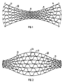
- Figure 1 shows a stack 10 of alternately arranged smooth 11 and corrugated 12 sheets.
- the length of the stack, the size and the number of sheets are not to scale, but are only intended to explain the principle.
- the corrugated sheets 12 have a smaller corrugation height and corrugation width in their central region than in their outer regions, so that channels 13 with a smaller cross-sectional area result in the central region than in the outer region, where the channels 14 have a larger cross-sectional area.
- the ends of such a stack 10 can be devoured in opposite directions, so that all the sheets follow approximately the course of an S, as a result of which honeycomb bodies of different cross sections can be produced.
- FIG. 2 shows the case of a sheet metal stack 20 which is positioned opposite to FIG. 1, in which channels 24 with a larger cross-sectional area occur in the central area and channels 23 with a smaller cross-sectional area in the outer areas.
- This stack is also constructed from smooth sheets 21 and from corrugated sheets 22, the corrugation heights and corrugation widths of the corrugated sheets 22 being greater in the central area than in the outer areas.
- the ends of such a stack can also be devoured in opposite directions, for example to fill a honeycomb body, as shown in FIG. 6. It is also possible to build honeycomb bodies from a plurality of such stacks analogously to the prior art.
- a stack of sheets for honeycomb bodies according to the invention can also contain corrugated sheets with the same corrugation height and corrugation width throughout, in particular on the top and bottom of the stack. It is also possible to construct honeycomb bodies from sheet metal stacks which are asymmetrical with respect to their central area, so that different channel cross sections are present in one end area of the stack than in the other end area. In this way, honeycomb bodies can be produced with almost any distribution of the mean channel cross-sections over the cross-sectional area, which can be advantageous for honeycomb bodies with an asymmetrical flow.
- FIGS. 3 and 4 Sheets which are suitable in principle for the construction of honeycomb bodies according to the invention are shown schematically in FIGS. 3 and 4.
- the corrugated sheet 32 shown between two smooth sheet-metal layers 31 has a small corrugation height h1 in area A and changes to a larger corrugation height h2 in transition area B, which continues in area C.
- the corrugated sheet 42 shown between two smooth sheet layers 41 has a corrugation height that increases continuously from left to right.
- FIGS. 3 and 4 can be extended symmetrically at one of their ends to form metal sheets as shown in FIGS. 1 and 2. They can also be continued asymmetrically or with a constant wave height at their ends, depending on the requirements of the honeycomb body to be formed.
- the difference between the small and large well heights and the number of areas with different well heights can also be selected within wide limits. For manufacturing reasons, however, a continuously increasing corrugation height or a sheet with only a few different corrugation heights will be considered.
- a ratio of the well heights h1: h2 from 1: 2 to 1:10, preferably about 1: 4, can be useful. With the preferred ratio, for example, honeycomb bodies can be built which have about 400 cpsi (channels per square inch) in the area of the small channel cross sections, while they have about 100 cpsi in the area of the large channel cross sections.
- corrugations were assumed which can be produced with involute teeth.
- an increase in the corrugation height is always accompanied by a corresponding increase in the mean corrugation width (corresponds to half the division).
- Such a relationship is advantageous for the present invention because of the favorable hydraulic cross sections of such channel shapes, but is not essential.
- the distribution of the channel cross sections according to the invention can also be achieved only by changing the corrugation widths (which results in parallel smooth sheet metal layers) or only by changing the corrugation heights (which can advantageously be produced by intermeshing corrugated rollers at different depths). Any interim solution is also possible.
- FIG. 5 shows a cross section through a honeycomb body, which is built up from three sheet metal stacks, the sheet metal stacks being bent by folding lines in a central region of the honeycomb body.
- the basic production method and the structure of such a honeycomb body are in the above. WO-90/03220.
- the lower part of the honeycomb body shown also corresponds exactly to the structure known there made of smooth 51 and corrugated metal sheets 52, which run approximately in an involute shape and form channels 53.
- the honeycomb body 50 shown shows an embodiment modified according to the invention (separated from the known structure by a broken line) with cross-sections of the channels 54 increasing outwards.
- the smooth 51 and corrugated 52 sheets can be fastened to a casing tube 55, preferably by joining technology by brazing.
- the metal sheets can also be connected to one another in a manner known per se, so that the honeycomb body 50 has the same stability as the honeycomb bodies known from the prior art and filled with metal sheets running in an involute shape.
- a honeycomb body 50 is formed from three or more sheet stacks according to FIG. 1, at least some of the corrugated sheets having different corrugation heights.
- Such honeycomb bodies can also be constructed from stacks according to FIG. It should also be pointed out that this is in no way a restriction to round cross sections, but oval, elliptical or irregular cross sections can also be filled with sheets of different corrugation heights.
- FIG. 6 shows, using the example of an elliptical cross-sectional shape, how a honeycomb body with approximately S-shaped sheet metal layers can be built up from a stack according to FIG.
- This honeycomb body 60 consists of approximately S-shaped smooth 61 and corrugated 62 sheets, which form channels 63 with small cross sections in the outer area and channels 64 with large cross sections in the inner area.
- To complete the honeycomb body 60 include other smooth and corrugated sheets, not shown, the corrugated sheets having the same corrugation height throughout. Round, oval, elliptical cross sections can also be filled well with approximately S-shaped, intertwined sheets, this being possible both with stacks according to FIG. 1 and with stacks according to FIG. 2, depending on whether the larger duct cross sections are desired inside or outside.
- the present invention is of particular importance for unevenly flowed catalyst carrier bodies in exhaust systems of motor vehicles, where a more uniform utilization of the catalytically active volume can be achieved through a corresponding distribution of the channel cross sections over the flowed cross-sectional area of the honeycomb body.
Landscapes
- Chemical & Material Sciences (AREA)
- Engineering & Computer Science (AREA)
- Chemical Kinetics & Catalysis (AREA)
- Materials Engineering (AREA)
- Organic Chemistry (AREA)
- Toxicology (AREA)
- Health & Medical Sciences (AREA)
- Combustion & Propulsion (AREA)
- Mechanical Engineering (AREA)
- General Engineering & Computer Science (AREA)
- Exhaust Gas After Treatment (AREA)
- Catalysts (AREA)
- Apparatus For Radiation Diagnosis (AREA)
- Transforming Light Signals Into Electric Signals (AREA)
- Measurement Of Radiation (AREA)
Abstract
Claims (10)
- Corps alvéolaire, en particulier corps support de catalyseur pour systèmes d'échappement de moteurs à combustion interne, avec des canaux (13, 14 ; 23, 24 ; 53, 54; 63, 64) traversables par un fluide dans une direction d'écoulement, construit à partir d'une pluralité de tôles distinctes (11, 12 ; 21, 22 ; 31, 32 ; 41, 42 ; 51, 52 ; 61, 62) configurées en un ou plusieurs empilements et imbriquées entre elles, dont au moins une partie (12 ; 22 ; 32 ; 42 ; 52; 62) desquelles comporte des structures s'étendant approximativement parallèlement à la direction d'écoulement pour former les canaux (13, 14 ; 23, 24; 53, 54; 63, 64), caractérisé en ce que les structures présentent au moins sur une partie de ces tôles structurées (12 ; 22 32; 42 ; 52 ; 62) des hauteurs de structure (hl, h2) et/ou des largeurs de structure qui se modifient de façon continue ou par paliers pour former des canaux (13, 14 ; 23, 24 ; 53, 54; 63, 64) avec des surfaces en section droite différentes.
- Corps alvéolaire selon la revendication 1, caractérisé en ce que que les tôles (11, 12 ; 21, 22 ; 31, 32 ; 41, 42 ; 51, 52 ; 61, 62) on au maximum une longueur qui correspond à deux fois l'étendue en section droite du corps alvéolaire, de préférence une longueur plus faible que celle de l'étendue en section droite.
- Corps alvéolaire selon la revendication 1, caractérisé en ce que les tôles distinctes (11, 12 ; 21, 22 ; 31, 32 ; 41, 42 ; 51, 52 ; 61, 62) sont plus courtes que 50 cm, de préférence plus courtes que 30 cm.
- Corps alvéolaire selon la revendication 1, 2 ou 3, caractérisé en ce qu'au moins une partie des tôles structurées (22 ; 62) présente en région d'extrémité une hauteur de structure (h1) et/ou une largeur de structure plus faible qu'en région médiane.
- Corps alvéolaire selon la revendication 1, 2 ou 3, caracté risé en ce qu'au moins une partie des tôles structurées (12 ; 52) présente en région d'extrémité une hauteur de structure (h2) et/ou une largeur de structure plus élevée qu'en région médiane.
- Corps alvéolaire selon la revendication 1, 2 ou 3, caracté risé en ce que les tôles (22, 32 ; 42, 62) sont configurées de telle manière que des petits canaux (23 ; 63) soient prédominants dans une région extérieure du corps alvéolaire et des gros canaux (24; 64) dans une région intérieure.
- Corps alvéolaire selon la revendication 1, 2 ou 3, caracté risé en ce que les tôles structurées (12, 32 ; 42, 52) sont configurées de telle manière que des gros canaux (14 ; 54) soient prédominants dans une région extérieure du corps alvéolaire et des petits canaux (13; 53) dans une région intérieure, la région intérieure pouvant aussi s'étendre de façon excentrée.
- Corps alvéolaire selon l'une des revendications précédentes, caractérisé en ce que les tôles (61, 62) sont courbées en une forme générale approximative de S.
- Corps alvéolaire selon l'une des revendications 1 à 8, ca ractérisé en ce que les tôles (51, 52) sont configurées à l'intérieur du corps alvéolaire en trois empilements ou plus imbriqués entre eux, au moins trois des empilements étant pliés chacun autour de ligne de pliage.
- Corps alvéolaire selon l'une des revendications précédentes, caractérisé en ce que les tôles (11, 12 ; 21, 22 ; 31, 32 ; 41, 42 ; 51, 52 ; 61, 62) sont des tôles approximativement lisses (11 ; 21 31 ; 41 ; 51 ; 61) et ondulées (12 ; 22 ; 32 ; 42 ; 52 ; 62) configurées de façon alternée, une partie des tôles ondulées (12 ; 22 ; 32 ; 42 ; 52 ; 62) présentant au moins deux hauteurs d'ondulation (h1, h2) différentes.
Applications Claiming Priority (2)
| Application Number | Priority Date | Filing Date | Title |
|---|---|---|---|
| DE4025434 | 1990-08-10 | ||
| DE4025434A DE4025434A1 (de) | 1990-08-10 | 1990-08-10 | Wabenkoerper mit querschnittsbereichen unterschiedlicher kanalgroessen, insbesondere katalysator-traegerkoerper |
Publications (2)
| Publication Number | Publication Date |
|---|---|
| EP0542805A1 EP0542805A1 (fr) | 1993-05-26 |
| EP0542805B1 true EP0542805B1 (fr) | 1994-01-19 |
Family
ID=6412044
Family Applications (1)
| Application Number | Title | Priority Date | Filing Date |
|---|---|---|---|
| EP91914048A Expired - Lifetime EP0542805B1 (fr) | 1990-08-10 | 1991-07-29 | Corps en nid d'abeilles ayant des canaux a sections transversales diverses, notamment corps de support de catalyseur |
Country Status (5)
| Country | Link |
|---|---|
| EP (1) | EP0542805B1 (fr) |
| JP (1) | JPH05509032A (fr) |
| DE (2) | DE4025434A1 (fr) |
| ES (1) | ES2048016T3 (fr) |
| WO (1) | WO1992002717A1 (fr) |
Cited By (2)
| Publication number | Priority date | Publication date | Assignee | Title |
|---|---|---|---|---|
| US5865864A (en) * | 1995-02-20 | 1999-02-02 | Emitec Gesellschaft Fuer Emissionstechnologie Mbh | Honeycomb body having channels of different flow resistance through which a fluid can flow and apparatus having the honeycomb body for cleaning exhaust gas |
| US6497130B2 (en) | 2000-02-11 | 2002-12-24 | Kemira Metalkat Oy | Method for corrugating a metal foil and packages of such foil |
Families Citing this family (19)
| Publication number | Priority date | Publication date | Assignee | Title |
|---|---|---|---|---|
| FI94455C (fi) * | 1992-08-28 | 1995-09-11 | Kemira Oy | Katalysaattori ja sen valmistusmenetelmä |
| DE4233404C2 (de) * | 1992-10-05 | 1994-08-18 | Degussa | Monolithischer Metallträgerkatalysator mit einem katalytisch beschichteten Wabenkörper |
| US5866230A (en) * | 1993-01-11 | 1999-02-02 | Emitec Gesellschaft Fuer Emissionstechnologie Gmbh | Extruded honeycomb body of ceramic and/or metallic material with increased flexibility |
| PL174466B1 (pl) * | 1994-09-12 | 1998-07-31 | Huta Baildon | Urządzenie do katalitycznego oczyszczania gazów z silników spalinowych oraz sposób wytwarzania urządzenia do katalitycznego oczyszczania gazów z silników spalinowych |
| FR2728303A1 (fr) * | 1994-12-16 | 1996-06-21 | Rosi Ets | Support de pot catalytique a enroulement spirale de feuillard ondule, et son procede de fabrication |
| DE19514986A1 (de) * | 1995-04-24 | 1996-10-31 | Audi Ag | Katalysator |
| JP3610720B2 (ja) * | 1997-03-03 | 2005-01-19 | 日産自動車株式会社 | メタル触媒担体の構造 |
| DE19740966C2 (de) * | 1997-09-17 | 1999-09-09 | Emitec Emissionstechnologie | Verfahren zum Herstellen eines metallischen Trägerkörpers sowie ein metallischer Trägerkörper für ein Abgassystem einer Verbrennungsmaschine |
| DE19824428B4 (de) * | 1998-05-30 | 2004-07-01 | Daimlerchrysler Ag | Abgaskatalysatorkörper mit unterschiedlichen, parallelen Zellstrukturbereichen |
| DE19959612A1 (de) * | 1999-12-10 | 2001-06-13 | Volkswagen Ag | Katalysatorkörper für eine Abgasreinigugnseinrichtung einer Verbrennungskraftmaschine |
| DE10057420A1 (de) * | 2000-11-20 | 2002-06-06 | Emitec Emissionstechnologie | Mehrstufiger Shiftreaktor und Reformeranlage |
| DE10057418A1 (de) * | 2000-11-20 | 2002-06-20 | Emitec Emissionstechnologie | Reaktoreinheit und Reformeranlage |
| DE10329002A1 (de) * | 2003-06-27 | 2005-01-20 | Emitec Gesellschaft Für Emissionstechnologie Mbh | Aufbau einer metallischen Wabenstruktur und Verfahren zu dessen Herstellung |
| DE102005028044A1 (de) * | 2005-06-17 | 2006-12-28 | Emitec Gesellschaft Für Emissionstechnologie Mbh | Herstellung von, insbesondere großen, Wabenkörpern für die mobile Abgasnachbehandlung |
| JP2007196156A (ja) * | 2006-01-27 | 2007-08-09 | Calsonic Kansei Corp | メタル担体及びメタル担体の製造方法 |
| CN104879196A (zh) * | 2014-02-28 | 2015-09-02 | 重庆江赛环保科技有限公司 | 变目数催化剂 |
| DE102014105770A1 (de) | 2014-04-24 | 2015-11-12 | Emitec Gesellschaft Für Emissionstechnologie Mbh | Verfahren zur Beeinflussung einer Fluidströmung |
| CN110006071B (zh) * | 2018-01-04 | 2024-05-17 | 华帝股份有限公司 | 红外线金属蜂窝体及其制作方法及红外线金属燃烧器 |
| CN113982724B (zh) * | 2021-10-12 | 2022-12-23 | 台州三元车辆净化器有限公司 | 新型金属蜂窝载体 |
Family Cites Families (13)
| Publication number | Priority date | Publication date | Assignee | Title |
|---|---|---|---|---|
| US3100140A (en) * | 1960-05-31 | 1963-08-06 | Calumet & Hecla | Catalytic automotive exhaust converter |
| DE2514129C3 (de) * | 1975-03-29 | 1979-03-01 | Basf Ag, 6700 Ludwigshafen | Vorrichtung zur Erzielung eines gleichmäßigen Strömungsprofils |
| JPS62174525A (ja) * | 1986-01-25 | 1987-07-31 | Toyota Motor Corp | 触媒コンバ−タ |
| DE3766263D1 (de) * | 1986-01-30 | 1991-01-03 | Nippon Steel Corp | Rostfreies band als katalysatortraeger fuer kraftfahrzeugabgase und verfahren zu seiner herstellung. |
| DE3760479D1 (en) * | 1986-05-12 | 1989-09-28 | Interatom | Honeycomb body, particularly a catalyst carrier, provided with opposedly folded metal sheet layers, and its manufacturing process |
| DE8801738U1 (de) * | 1988-02-11 | 1988-03-31 | kabelmetal electro GmbH, 3000 Hannover | Ein- oder mehradriges beheizbares elektrisches Kabel |
| DE8801788U1 (de) * | 1988-02-11 | 1989-06-15 | Emitec Gesellschaft für Emissionstechnologie mbH, 53797 Lohmar | Katalysator-Trägerkörper mit S-förmigen, teilweise verstärkten Blechlagen |
| DE3809105A1 (de) * | 1988-03-18 | 1989-09-28 | Eberspaecher J | Vorrichtung zur katalytischen reinigung der abgase einer brennkraftmachine und verfahren zu deren herstellung |
| DE3809490C1 (fr) * | 1988-03-22 | 1989-05-11 | Sueddeutsche Kuehlerfabrik Julius Fr. Behr Gmbh & Co Kg, 7000 Stuttgart, De | |
| KR940005668B1 (ko) * | 1988-08-13 | 1994-06-22 | 우스이 고꾸사이 산교 가부시끼가이샤 | 배기가스 정화용 촉매를 담지하기 위한 금속제 담지모체(擔持母體) |
| JPH03502660A (ja) * | 1988-09-22 | 1991-06-20 | エミテツク ゲゼルシヤフト フユア エミツシオンステクノロギー ミツト ベシユレンクテル ハフツング | 複数の絡み合った金属板積層体から成るハニカム体、特に触媒担体 |
| JP2745222B2 (ja) * | 1988-12-13 | 1998-04-28 | 臼井国際産業株式会社 | 排気ガス浄化用触媒の金属製担時母体 |
| DE8908738U1 (de) * | 1989-07-18 | 1989-09-07 | Emitec Gesellschaft für Emissionstechnologie mbH, 5204 Lohmar | Wabenkörper mit internen Strömungsleitflächen, insbesondere Katalysatorkörper für Kraftfahrzeuge |
-
1990
- 1990-08-10 DE DE4025434A patent/DE4025434A1/de not_active Withdrawn
-
1991
- 1991-07-29 ES ES91914048T patent/ES2048016T3/es not_active Expired - Lifetime
- 1991-07-29 EP EP91914048A patent/EP0542805B1/fr not_active Expired - Lifetime
- 1991-07-29 WO PCT/EP1991/001423 patent/WO1992002717A1/fr not_active Ceased
- 1991-07-29 DE DE91914048T patent/DE59100919D1/de not_active Expired - Fee Related
- 1991-07-29 JP JP3512761A patent/JPH05509032A/ja active Pending
Cited By (3)
| Publication number | Priority date | Publication date | Assignee | Title |
|---|---|---|---|---|
| US5865864A (en) * | 1995-02-20 | 1999-02-02 | Emitec Gesellschaft Fuer Emissionstechnologie Mbh | Honeycomb body having channels of different flow resistance through which a fluid can flow and apparatus having the honeycomb body for cleaning exhaust gas |
| DE19680093B4 (de) * | 1995-02-20 | 2006-08-24 | Emitec Gesellschaft Für Emissionstechnologie Mbh | Wabenkörper mit von einem Fluid durchströmbaren Kanälen von unterschiedlichem Strömungswiderstand |
| US6497130B2 (en) | 2000-02-11 | 2002-12-24 | Kemira Metalkat Oy | Method for corrugating a metal foil and packages of such foil |
Also Published As
| Publication number | Publication date |
|---|---|
| DE4025434A1 (de) | 1992-02-13 |
| WO1992002717A1 (fr) | 1992-02-20 |
| JPH05509032A (ja) | 1993-12-16 |
| ES2048016T3 (es) | 1994-03-01 |
| EP0542805A1 (fr) | 1993-05-26 |
| DE59100919D1 (de) | 1994-03-03 |
Similar Documents
| Publication | Publication Date | Title |
|---|---|---|
| EP0542805B1 (fr) | Corps en nid d'abeilles ayant des canaux a sections transversales diverses, notamment corps de support de catalyseur | |
| EP0542775B1 (fr) | Corps metallique monolithique en nid d'abeilles a nombre variable de canaux | |
| EP0484364B1 (fr) | Corps en nid d'abeilles, a aretes internes d'entree, notamment support de catalyseur pour vehicule automobile | |
| EP0386013B1 (fr) | Agencement catalyseur avec corps de guidage de l'ecoulement | |
| EP0454712B1 (fr) | Structure alveolaire metallique | |
| DE19680093B4 (de) | Wabenkörper mit von einem Fluid durchströmbaren Kanälen von unterschiedlichem Strömungswiderstand | |
| DE2902779C2 (de) | Matrix für einen katalytischen Reaktor zur Abgasreinigung bei Brennkraftmaschinen | |
| EP0784507B1 (fr) | Microstructures croisees | |
| EP1089819B1 (fr) | Corps en nids d'abeilles metallique monolithique avec un nombre de canaux variable | |
| EP0186801A2 (fr) | Matrice porteuse en particulier pour un réacteur catalytique pour la purification des gaz d'échappement | |
| WO1990003220A1 (fr) | Corps alveolaire, en particulier support de catalyseur, consistant en une pluralite de fardeaux de tole superposes | |
| DE29723721U1 (de) | Konischer Wabenkörper mit Longitudinalstrukturen | |
| EP0336106B1 (fr) | Procédé de fabrication d'un support pour réacteur catalytique | |
| EP1848534B1 (fr) | Corps en nid d'abeilles a cavites internes | |
| EP0577117A2 (fr) | Procédé pour la fabrication d'un catalyseur | |
| DE10356997A1 (de) | Partikelfilter | |
| EP2864604B1 (fr) | Corps en nid d'abeilles conique avec des canaux en orientation radiale et oblique | |
| EP0762934B1 (fr) | Nid d'abeilles compose de couches de toles d'epaisseurs differentes | |
| DE3844350A1 (de) | Traegerkoerper fuer einen katalytischen reaktor zur abgasreinigung | |
| EP0969929A1 (fr) | Corps en nid d'abeilles, notamment corps de support de catalyseur, avec une paroi a structure renforcee | |
| WO1994015712A1 (fr) | Element alveole extrude en matiere ceramique et/ou metallique, ayant une flexibilite renforcee | |
| EP3797220B1 (fr) | Nid d'abeille et procédé de fabrication du nid d'abeille | |
| EP3615778B1 (fr) | Corps en nid d'abeilles métallique avec des microstructures favorisant l'adhésion | |
| DE8705723U1 (de) | Wabenkörper zur Reinigung der Abgase von Verbrennungskraftmaschinen | |
| DE9422242U1 (de) | Wabenkörper aus Blechlagen unterschiedlicher Vormaterialien |
Legal Events
| Date | Code | Title | Description |
|---|---|---|---|
| PUAI | Public reference made under article 153(3) epc to a published international application that has entered the european phase |
Free format text: ORIGINAL CODE: 0009012 |
|
| 17P | Request for examination filed |
Effective date: 19921126 |
|
| AK | Designated contracting states |
Kind code of ref document: A1 Designated state(s): DE ES FR GB IT SE |
|
| 17Q | First examination report despatched |
Effective date: 19930701 |
|
| GRAA | (expected) grant |
Free format text: ORIGINAL CODE: 0009210 |
|
| AK | Designated contracting states |
Kind code of ref document: B1 Designated state(s): DE ES FR GB IT SE |
|
| REG | Reference to a national code |
Ref country code: ES Ref legal event code: FG2A Ref document number: 2048016 Country of ref document: ES Kind code of ref document: T3 |
|
| REF | Corresponds to: |
Ref document number: 59100919 Country of ref document: DE Date of ref document: 19940303 |
|
| ITF | It: translation for a ep patent filed | ||
| GBT | Gb: translation of ep patent filed (gb section 77(6)(a)/1977) |
Effective date: 19940323 |
|
| ET | Fr: translation filed | ||
| PLBE | No opposition filed within time limit |
Free format text: ORIGINAL CODE: 0009261 |
|
| STAA | Information on the status of an ep patent application or granted ep patent |
Free format text: STATUS: NO OPPOSITION FILED WITHIN TIME LIMIT |
|
| 26N | No opposition filed | ||
| EAL | Se: european patent in force in sweden |
Ref document number: 91914048.3 |
|
| PGFP | Annual fee paid to national office [announced via postgrant information from national office to epo] |
Ref country code: SE Payment date: 19960719 Year of fee payment: 6 |
|
| PGFP | Annual fee paid to national office [announced via postgrant information from national office to epo] |
Ref country code: ES Payment date: 19960729 Year of fee payment: 6 |
|
| PG25 | Lapsed in a contracting state [announced via postgrant information from national office to epo] |
Ref country code: SE Effective date: 19970730 Ref country code: ES Free format text: LAPSE BECAUSE OF THE APPLICANT RENOUNCES Effective date: 19970730 |
|
| EUG | Se: european patent has lapsed |
Ref document number: 91914048.3 |
|
| REG | Reference to a national code |
Ref country code: ES Ref legal event code: FD2A Effective date: 20001009 |
|
| REG | Reference to a national code |
Ref country code: GB Ref legal event code: IF02 |
|
| PGFP | Annual fee paid to national office [announced via postgrant information from national office to epo] |
Ref country code: DE Payment date: 20080729 Year of fee payment: 18 |
|
| PGFP | Annual fee paid to national office [announced via postgrant information from national office to epo] |
Ref country code: FR Payment date: 20080722 Year of fee payment: 18 Ref country code: IT Payment date: 20080728 Year of fee payment: 18 |
|
| PGFP | Annual fee paid to national office [announced via postgrant information from national office to epo] |
Ref country code: GB Payment date: 20080723 Year of fee payment: 18 |
|
| GBPC | Gb: european patent ceased through non-payment of renewal fee |
Effective date: 20090729 |
|
| REG | Reference to a national code |
Ref country code: FR Ref legal event code: ST Effective date: 20100331 |
|
| PG25 | Lapsed in a contracting state [announced via postgrant information from national office to epo] |
Ref country code: FR Free format text: LAPSE BECAUSE OF NON-PAYMENT OF DUE FEES Effective date: 20090731 |
|
| PG25 | Lapsed in a contracting state [announced via postgrant information from national office to epo] |
Ref country code: GB Free format text: LAPSE BECAUSE OF NON-PAYMENT OF DUE FEES Effective date: 20090729 |
|
| PG25 | Lapsed in a contracting state [announced via postgrant information from national office to epo] |
Ref country code: DE Free format text: LAPSE BECAUSE OF NON-PAYMENT OF DUE FEES Effective date: 20100202 |
|
| PG25 | Lapsed in a contracting state [announced via postgrant information from national office to epo] |
Ref country code: IT Free format text: LAPSE BECAUSE OF NON-PAYMENT OF DUE FEES Effective date: 20090729 |