EP0315052A1 - Echangeur de chaleur à courants croisés fait de plastique - Google Patents
Echangeur de chaleur à courants croisés fait de plastique Download PDFInfo
- Publication number
- EP0315052A1 EP0315052A1 EP88117901A EP88117901A EP0315052A1 EP 0315052 A1 EP0315052 A1 EP 0315052A1 EP 88117901 A EP88117901 A EP 88117901A EP 88117901 A EP88117901 A EP 88117901A EP 0315052 A1 EP0315052 A1 EP 0315052A1
- Authority
- EP
- European Patent Office
- Prior art keywords
- cross
- heat exchanger
- exchanger body
- hollow chambers
- cover layers
- Prior art date
- Legal status (The legal status is an assumption and is not a legal conclusion. Google has not performed a legal analysis and makes no representation as to the accuracy of the status listed.)
- Ceased
Links
- 239000004033 plastic Substances 0.000 title claims description 17
- 229920003023 plastic Polymers 0.000 title claims description 17
- 125000006850 spacer group Chemical group 0.000 claims description 15
- 238000000576 coating method Methods 0.000 abstract 1
- 238000003466 welding Methods 0.000 description 9
- 238000004519 manufacturing process Methods 0.000 description 6
- 238000001125 extrusion Methods 0.000 description 4
- 239000000463 material Substances 0.000 description 3
- 239000000853 adhesive Substances 0.000 description 2
- 230000001070 adhesive effect Effects 0.000 description 2
- 230000002349 favourable effect Effects 0.000 description 2
- 239000002184 metal Substances 0.000 description 2
- 229910052751 metal Inorganic materials 0.000 description 2
- 238000000034 method Methods 0.000 description 2
- -1 polyethylene Polymers 0.000 description 2
- 239000004698 Polyethylene Substances 0.000 description 1
- 239000004721 Polyphenylene oxide Substances 0.000 description 1
- 239000004743 Polypropylene Substances 0.000 description 1
- 239000004793 Polystyrene Substances 0.000 description 1
- 238000004026 adhesive bonding Methods 0.000 description 1
- 230000015572 biosynthetic process Effects 0.000 description 1
- 239000004020 conductor Substances 0.000 description 1
- 238000010276 construction Methods 0.000 description 1
- 238000001816 cooling Methods 0.000 description 1
- 238000006477 desulfuration reaction Methods 0.000 description 1
- 230000023556 desulfurization Effects 0.000 description 1
- 230000009969 flowable effect Effects 0.000 description 1
- 238000010438 heat treatment Methods 0.000 description 1
- 238000002844 melting Methods 0.000 description 1
- 230000008018 melting Effects 0.000 description 1
- 150000002739 metals Chemical class 0.000 description 1
- 229920003229 poly(methyl methacrylate) Polymers 0.000 description 1
- 229920002492 poly(sulfone) Polymers 0.000 description 1
- 239000004417 polycarbonate Substances 0.000 description 1
- 229920000515 polycarbonate Polymers 0.000 description 1
- 229920006393 polyether sulfone Polymers 0.000 description 1
- 229920001601 polyetherimide Polymers 0.000 description 1
- 229920000573 polyethylene Polymers 0.000 description 1
- 239000004926 polymethyl methacrylate Substances 0.000 description 1
- 229920006380 polyphenylene oxide Polymers 0.000 description 1
- 229920001155 polypropylene Polymers 0.000 description 1
- 229920005553 polystyrene-acrylate Polymers 0.000 description 1
- 229920000915 polyvinyl chloride Polymers 0.000 description 1
- 239000004800 polyvinyl chloride Substances 0.000 description 1
- 230000003068 static effect Effects 0.000 description 1
- 239000012815 thermoplastic material Substances 0.000 description 1
Images
Classifications
-
- F—MECHANICAL ENGINEERING; LIGHTING; HEATING; WEAPONS; BLASTING
- F28—HEAT EXCHANGE IN GENERAL
- F28D—HEAT-EXCHANGE APPARATUS, NOT PROVIDED FOR IN ANOTHER SUBCLASS, IN WHICH THE HEAT-EXCHANGE MEDIA DO NOT COME INTO DIRECT CONTACT
- F28D9/00—Heat-exchange apparatus having stationary plate-like or laminated conduit assemblies for both heat-exchange media, the media being in contact with different sides of a conduit wall
- F28D9/0062—Heat-exchange apparatus having stationary plate-like or laminated conduit assemblies for both heat-exchange media, the media being in contact with different sides of a conduit wall the conduits for one heat-exchange medium being formed by spaced plates with inserted elements
-
- B—PERFORMING OPERATIONS; TRANSPORTING
- B27—WORKING OR PRESERVING WOOD OR SIMILAR MATERIAL; NAILING OR STAPLING MACHINES IN GENERAL
- B27N—MANUFACTURE BY DRY PROCESSES OF ARTICLES, WITH OR WITHOUT ORGANIC BINDING AGENTS, MADE FROM PARTICLES OR FIBRES CONSISTING OF WOOD OR OTHER LIGNOCELLULOSIC OR LIKE ORGANIC MATERIAL
- B27N5/00—Manufacture of non-flat articles
- B27N5/02—Hollow articles
-
- F—MECHANICAL ENGINEERING; LIGHTING; HEATING; WEAPONS; BLASTING
- F28—HEAT EXCHANGE IN GENERAL
- F28F—DETAILS OF HEAT-EXCHANGE AND HEAT-TRANSFER APPARATUS, OF GENERAL APPLICATION
- F28F21/00—Constructions of heat-exchange apparatus characterised by the selection of particular materials
- F28F21/06—Constructions of heat-exchange apparatus characterised by the selection of particular materials of plastics material
- F28F21/065—Constructions of heat-exchange apparatus characterised by the selection of particular materials of plastics material the heat-exchange apparatus employing plate-like or laminated conduits
-
- Y—GENERAL TAGGING OF NEW TECHNOLOGICAL DEVELOPMENTS; GENERAL TAGGING OF CROSS-SECTIONAL TECHNOLOGIES SPANNING OVER SEVERAL SECTIONS OF THE IPC; TECHNICAL SUBJECTS COVERED BY FORMER USPC CROSS-REFERENCE ART COLLECTIONS [XRACs] AND DIGESTS
- Y10—TECHNICAL SUBJECTS COVERED BY FORMER USPC
- Y10S—TECHNICAL SUBJECTS COVERED BY FORMER USPC CROSS-REFERENCE ART COLLECTIONS [XRACs] AND DIGESTS
- Y10S165/00—Heat exchange
- Y10S165/355—Heat exchange having separate flow passage for two distinct fluids
- Y10S165/356—Plural plates forming a stack providing flow passages therein
- Y10S165/373—Adjacent heat exchange plates having joined bent edge flanges for forming flow channels therebetween
- Y10S165/384—Thermally bonded side edges
Definitions
- the invention relates to a cross-flow heat exchanger body made of plastic, which is composed of a stack of extruded multi-wall sheets and is used for heat exchange between flowing media.
- a complete heat exchanger which also includes the supply and discharge lines for the flowing media along with the necessary header boxes, the term "heat exchanger body" is intended only to refer to the arrangement of flowable channels between which heat is transferred.
- plastics are generally poorer heat conductors than metals, plastic heat exchangers have become of considerable importance for applications where simple and cheap production methods and low material costs are important, which would not be achievable with metal heat exchangers.
- the lower weight can also be decisive for the choice of plastic as the material for heat exchangers.
- Extruded multi-wall sheets made of plastic consisting of two flat, parallel cover layers and interposed webs that are co-extruded in one piece with the cover layers and enclose hollow chambers that can be flowed through in parallel, are excellent structural elements for heat exchanger bodies because of their low manufacturing costs.
- multi-wall sheets made of plastic are glued to a stack by means of an adhesive applied to the cover layers.
- EP-B 167 938 in such an arrangement, in order to simplify the production process, the stacked multi-wall sheets are connected to one another only in the region of their end faces, for example by means of an interposed heating wire which is heated above the melting temperature of the plastic by applying an electrical voltage and for welding the superimposed ones Plastic surfaces leads.
- Cross-flow heat exchanger bodies which are composed of extruded multi-wall sheets made of plastic and contain a cross-flowable hollow chamber between two parallel through-flow multi-wall sheets, are also known from FR-A 2 469 684 and DE-A 31 37 296. In both cases, the multi-skin sheets have a constant profile up to the end faces.
- a connection technique that allows a quick and easy construction of a heat exchanger body from a plurality of multi-wall sheets is not described in any of these publications.
- a disadvantage of the known heat exchanger bodies is the unfavorable inflow profile of the open end faces.
- the aim of the invention was to create a cross-flow heat exchanger body from a stack of extruded multi-wall sheets made of plastic, which has an advantageous inflow profile and can be produced simply and reliably.
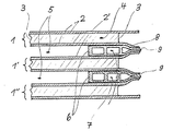
- the hollow chambers 4 in all multi-wall sheets 1 are aligned in parallel and open at the front ends and can therefore be flowed through in the extrusion direction of the multi-wall sheets.
- the hollow chambers 5 enclosed by the multi-wall sheets 1 are closed on the end faces of the multi-wall sheets and open on the sides of the heat exchanger body on which the multi-wall sheets are closed by their edge webs and can therefore be flowed through transversely to the hollow chambers 4.
- the multi-wall sheets used to build up the heat exchanger body are produced by extrusion from thermoplastic material.
- the plastic must be resistant to the media flowing through and have a softening temperature above the highest operating temperature. If these requirements are met, all extrudable plastics can be used, such as polyethylene, polypropylene, polyvinyl chloride, polystyrene or polymethyl methacrylate.
- Polycarbonate and polysulfone plastics can be used for operating temperatures above 100 to approximately 120 ° C. For operating temperatures up to 150 ° C e.g. Polyphenylene oxides, polyetherimides or polyether sulfones can be used.
- Appropriate dimensions of the multi-wall sheets are a length of 500 to 3000 mm, a width of 300 to 2000 mm and a thickness of 3 to 30 mm, but these dimensions are not critical.
- the cover layers 2 and the webs 3 can have a - usually approximately the same - thickness in accordance with the static requirements at the operating temperature from 0.5 to 5 mm.
- the hollow chambers 4 are delimited by the webs 3 and the intermediate sections of the cover layers 2.
- the webs can be perpendicular to the cover layers or at an angle to it.
- the heat transfer between the flowing medium and the multi-wall sheet is improved if a suitable geometry of the hollow chamber cross section ensures a turbulent flow. This can also be promoted by corrugating the webs in the longitudinal direction.
- the heat exchanger body usually consists of more than 2, preferably from 5 to 100 web plates 1 connected to one another to form a stack.
- Their cover layers 2, 2 ', at least insofar as they delimit hollow chambers 5, are inclined towards one another at the front ends over the intermediate hollow chambers and tightly connected to each other across the entire width of the multi-skin sheets.
- the area in which the cover layers are inclined can, for example, extend over a length of one to two times the thickness of the multi-wall sheet.
- the webs 3 are preferably cut out to this depth, in particular milled out.
- the inclination of two a hollow chamber 5 delimiting cover layers 2, 2 ' is generally the same size, so that they are in the central plane of the Meet hollow chamber 5 and are tightly connected there.
- the thickness of the hollow chambers 5 is determined by the strength of the inclination of the cover layers. This thickness is expediently approximately the same size as that of the hollow chambers 4 within the multi-wall sheets 1, but the ratio of these thicknesses can be in a wider range from approximately 1: 3 to 3: 1.
- connection of the mutually inclined ends of the cover layers 2.2 ' should be so tight that a passage of the media flowing through the hollow chambers is largely or completely prevented in both directions.
- a tight connection is achieved by clamping U-profiles, by gluing or preferably by welding to a weld 9.
- the heat exchanger body has a strength which is not sufficient for all purposes.
- spacers 6 are preferably arranged in the hollow chambers of the thickness of the hollow chambers and support the adjacent cover layers 2, 2 '.
- the spacers 6 are preferably arranged continuously parallel to the end faces of the web plates close to the inclined ends. They can contain hollow chambers 7 which, like the hollow chambers 5, can be flowed through transversely to the extrusion direction of the multi-wall sheets. It is advantageous if the spacers 6 have lateral extensions 8 with which they protrude into the connection of the cover layers and also with these are connected.
- the inclined ends of the cover layers 2, 2 'and the extensions 8 of the spacers together form the weld seam 9.
- the spacers can basically consist of any suitable material of sufficient pressure resistance, they are preferably made of the same plastic as the multi-wall sheets 1. You can including the lateral extensions 8 have been produced by extrusion. If the heat exchanger body has a considerable length, it may be expedient to increase its rigidity and compressive strength by arranging further spacers at one or more locations between the end faces of the web plates. It is also possible to use web plates as spacers, which essentially fill the hollow chambers 5. They can be connected to one another at the ends protruding from the heat exchanger body in the same way as the multi-wall sheets 1 and are then distinguished by equally good flow properties.
- the new heat exchanger bodies are easy to manufacture. For this purpose, all web plates 1 are cut to the same desired length and their webs are cut out to the depth of the necessary deformation.
- the multi-wall sheets, the cover layers of which are not yet inclined on their end faces, are stacked at a distance which corresponds to the desired thickness of the hollow chambers 5, so that their end faces lie in one plane. This is preferably done by inserting a spacer 6 on each end face of a multi-wall sheet.
- the front ends of the cover layers 2, 2 ' warmed up to the softening temperature of the plastic by placing continuously heated welding jaws and then pressed together in pairs by bringing the welding jaws closer together.
- spacers 6 with extensions 8 are also used, these are heated at the same time and - if necessary - also deformed. If a connection by plug-on profiles or by adhesive is intended, the deformed ends of the multi-wall sheets can be allowed to cool in this position and then connected. The deformed ends of the cover layers and, if appropriate, the extensions of the spacers 6 are preferably heated in the contact region until they melt and a weld seam 9 is formed.
- the profile of the welding jaws should be such that it forms the ends of the cover layers 2 and 2 'and promotes the formation of funnel-shaped entrances into the hollow chambers 4 with a favorable inflow profile.
- the welding jaws preferably have a semi-circular or semi-oval profile. If multi-wall sheets are used in which the webs are not cut out to the depth of the desired deformation, comb-like welding jaws are used which engage in the ends of the hollow chambers 4 and likewise heat the webs 3 to the softening temperature.
- the welding jaws can be removed. As a rule, it is not necessary to allow the weld seam to cool down together with the welding jaws. This results in a high working speed.
Landscapes
- Engineering & Computer Science (AREA)
- Physics & Mathematics (AREA)
- Thermal Sciences (AREA)
- Mechanical Engineering (AREA)
- General Engineering & Computer Science (AREA)
- Life Sciences & Earth Sciences (AREA)
- Manufacturing & Machinery (AREA)
- Wood Science & Technology (AREA)
- Forests & Forestry (AREA)
- Heat-Exchange Devices With Radiators And Conduit Assemblies (AREA)
Applications Claiming Priority (2)
| Application Number | Priority Date | Filing Date | Title |
|---|---|---|---|
| DE8714559U DE8714559U1 (de) | 1987-11-02 | 1987-11-02 | Kreuzstromwärmetauscher aus Kunststoff |
| DE8714559U | 1987-11-02 |
Publications (1)
| Publication Number | Publication Date |
|---|---|
| EP0315052A1 true EP0315052A1 (fr) | 1989-05-10 |
Family
ID=6813660
Family Applications (1)
| Application Number | Title | Priority Date | Filing Date |
|---|---|---|---|
| EP88117901A Ceased EP0315052A1 (fr) | 1987-11-02 | 1988-10-27 | Echangeur de chaleur à courants croisés fait de plastique |
Country Status (4)
| Country | Link |
|---|---|
| US (1) | US4907648A (fr) |
| EP (1) | EP0315052A1 (fr) |
| JP (1) | JPH01150794A (fr) |
| DE (1) | DE8714559U1 (fr) |
Cited By (6)
| Publication number | Priority date | Publication date | Assignee | Title |
|---|---|---|---|---|
| DE3926283A1 (de) * | 1989-08-09 | 1991-02-14 | Menerga Apparatebau Gmbh | Rekuperativ-hohlkammerplatten-waermetauscher mit aerodynamischen an- und abstroemflaechen |
| WO1993016346A1 (fr) * | 1992-02-06 | 1993-08-19 | Aalander Johan | Procede de fabrication d'echangeurs de chaleur |
| EP0840084A2 (fr) | 1996-10-30 | 1998-05-06 | REHAU AG + Co | Echangeur de chaleur |
| US6983788B2 (en) * | 1998-11-09 | 2006-01-10 | Building Performance Equipment, Inc. | Ventilating system, heat exchanger and methods |
| WO2008025359A3 (fr) * | 2006-08-28 | 2009-02-05 | Dantherm Air Handling As | Procédé de fabrication d'un échangeur de chaleur |
| DE102013015939A1 (de) * | 2013-09-26 | 2015-03-26 | Inventer Gmbh | Dezentrales Lüftungsgerät mit Rekuperator für den Wandeinbau |
Families Citing this family (17)
| Publication number | Priority date | Publication date | Assignee | Title |
|---|---|---|---|---|
| US5178124A (en) * | 1991-08-12 | 1993-01-12 | Rheem Manufacturing Company | Plastic secondary heat exchanger apparatus for a high efficiency condensing furnace |
| US5271376A (en) * | 1991-08-12 | 1993-12-21 | Rheem Manufacturing Company | Serpentined tubular heat exchanger apparatus for a fuel-fired forced air heating furnace |
| DE4237117A1 (de) * | 1992-11-03 | 1994-05-05 | Bosch Siemens Hausgeraete | Verfahren zum Herstellen eines Pakets von Wärmetauscher-Platten für einen Haushalt-Wäschetrockner, Werkzeug für ein solches Herstellungsverfahren und nach diesem Verfahren hergestelltes Plattenpaket |
| JPH09184692A (ja) * | 1995-12-28 | 1997-07-15 | Ebara Corp | 熱交換エレメント |
| GB2311845B (en) * | 1996-02-09 | 1998-03-11 | Roy George Barton | Gas-to-gas heat exchanger units |
| US6378604B1 (en) | 1999-06-28 | 2002-04-30 | Jon Charles Feind | To heat exchanger |
| US20060260790A1 (en) * | 2005-05-18 | 2006-11-23 | Mark Theno | Heat exchanger core |
| GB2459480B8 (en) * | 2008-04-23 | 2013-07-24 | Denso Corp | A heat exchanger, a method of making a heat exchanger and a kit of parts for making a heat exchanger |
| DE102009033157A1 (de) * | 2009-07-13 | 2011-01-27 | Menerga Gmbh | Plattenwärmeübertrager |
| KR101440723B1 (ko) * | 2013-03-14 | 2014-09-17 | 정인숙 | 현열교환기, 이를 포함하는 열회수 환기장치, 및 그 해빙운전과 점검운전 방법 |
| DE102014001575A1 (de) * | 2013-03-27 | 2014-10-02 | Modine Manufacturing Co. | Luft-Luft-Wärmetauscher |
| DE102015104959B4 (de) | 2015-03-31 | 2019-01-10 | Carsten Falley | Gegenstromplattenwärmeübertrager |
| WO2016187598A1 (fr) | 2015-05-20 | 2016-11-24 | Other Lab, Llc | Système d'échangeur de chaleur à membrane et procédé |
| WO2019075121A1 (fr) | 2017-10-10 | 2019-04-18 | Other Lab, Llc | Procédé et système d'échangeur de chaleur conformable |
| US11253958B2 (en) * | 2019-01-29 | 2022-02-22 | Treau, Inc. | Polymer film heat exchanger sealing system and method |
| US20200400377A1 (en) * | 2019-06-18 | 2020-12-24 | Hamilton Sundstrand Corporation | Heat exchanger closure bar |
| US12467693B1 (en) * | 2024-11-25 | 2025-11-11 | Alexander Levin | Dry cooling tower |
Citations (7)
| Publication number | Priority date | Publication date | Assignee | Title |
|---|---|---|---|---|
| US1409967A (en) * | 1920-10-29 | 1922-03-21 | Prat Emile | Heat exchanger |
| US2959401A (en) * | 1957-11-27 | 1960-11-08 | Modine Mfg Co | Plate-fin type heat exchanger and method of making the same |
| US3274672A (en) * | 1963-06-04 | 1966-09-27 | Air Preheater | Method of making a heat exchanger |
| FR2318398A1 (fr) * | 1975-07-18 | 1977-02-11 | Munters Ab Carl | Procede de realisation d'un corps d'echange de chaleur pour des echangeurs a recuperation |
| FR2449261A1 (fr) * | 1979-02-15 | 1980-09-12 | Hoval Interliz Ag | Echangeur de chaleur du type comportant un bloc echangeur a plaques |
| EP0044561A2 (fr) * | 1980-07-21 | 1982-01-27 | MüANYAGIPARI KUTATO INTEZET | Echangeur de chaleur, particulièrement pour échange de chaleur entre fluides gazeux |
| DE3137296A1 (de) * | 1981-09-18 | 1983-04-14 | Karl-Heinz Ing.(Grad.) 4715 Ascheberg Beckmann | Platten-waermetauscher |
Family Cites Families (4)
| Publication number | Priority date | Publication date | Assignee | Title |
|---|---|---|---|---|
| US2310121A (en) * | 1939-12-04 | 1943-02-02 | Paul A Scherer | Apparatus for the transfer of sensible and latent heat |
| US2953110A (en) * | 1954-01-22 | 1960-09-20 | W J Fraser & Co Ltd | Reciprocally folded sheet metal structures |
| DE2751115A1 (de) * | 1977-11-16 | 1979-05-23 | Klaus Ing Grad Rennebeck | Formkoerper mit etwa wabenaehnlicher struktur fuer waermetauscher, wascher o.dgl. |
| EP0167938B1 (fr) * | 1984-07-04 | 1987-09-30 | Röhm Gmbh | Corps échangeur de chaleur en matière plastique |
-
1987
- 1987-11-02 DE DE8714559U patent/DE8714559U1/de not_active Expired
-
1988
- 1988-10-27 EP EP88117901A patent/EP0315052A1/fr not_active Ceased
- 1988-10-31 US US07/264,849 patent/US4907648A/en not_active Expired - Fee Related
- 1988-11-02 JP JP63276356A patent/JPH01150794A/ja active Pending
Patent Citations (7)
| Publication number | Priority date | Publication date | Assignee | Title |
|---|---|---|---|---|
| US1409967A (en) * | 1920-10-29 | 1922-03-21 | Prat Emile | Heat exchanger |
| US2959401A (en) * | 1957-11-27 | 1960-11-08 | Modine Mfg Co | Plate-fin type heat exchanger and method of making the same |
| US3274672A (en) * | 1963-06-04 | 1966-09-27 | Air Preheater | Method of making a heat exchanger |
| FR2318398A1 (fr) * | 1975-07-18 | 1977-02-11 | Munters Ab Carl | Procede de realisation d'un corps d'echange de chaleur pour des echangeurs a recuperation |
| FR2449261A1 (fr) * | 1979-02-15 | 1980-09-12 | Hoval Interliz Ag | Echangeur de chaleur du type comportant un bloc echangeur a plaques |
| EP0044561A2 (fr) * | 1980-07-21 | 1982-01-27 | MüANYAGIPARI KUTATO INTEZET | Echangeur de chaleur, particulièrement pour échange de chaleur entre fluides gazeux |
| DE3137296A1 (de) * | 1981-09-18 | 1983-04-14 | Karl-Heinz Ing.(Grad.) 4715 Ascheberg Beckmann | Platten-waermetauscher |
Cited By (8)
| Publication number | Priority date | Publication date | Assignee | Title |
|---|---|---|---|---|
| DE3926283A1 (de) * | 1989-08-09 | 1991-02-14 | Menerga Apparatebau Gmbh | Rekuperativ-hohlkammerplatten-waermetauscher mit aerodynamischen an- und abstroemflaechen |
| WO1993016346A1 (fr) * | 1992-02-06 | 1993-08-19 | Aalander Johan | Procede de fabrication d'echangeurs de chaleur |
| US5474639A (en) * | 1992-02-06 | 1995-12-12 | Alander; Johan | Method for manufacturing heat exchangers |
| EP0840084A2 (fr) | 1996-10-30 | 1998-05-06 | REHAU AG + Co | Echangeur de chaleur |
| US6983788B2 (en) * | 1998-11-09 | 2006-01-10 | Building Performance Equipment, Inc. | Ventilating system, heat exchanger and methods |
| US7640662B2 (en) | 1998-11-09 | 2010-01-05 | Building Performance Equipment, Inc. | Method of making heat exchangers |
| WO2008025359A3 (fr) * | 2006-08-28 | 2009-02-05 | Dantherm Air Handling As | Procédé de fabrication d'un échangeur de chaleur |
| DE102013015939A1 (de) * | 2013-09-26 | 2015-03-26 | Inventer Gmbh | Dezentrales Lüftungsgerät mit Rekuperator für den Wandeinbau |
Also Published As
| Publication number | Publication date |
|---|---|
| US4907648A (en) | 1990-03-13 |
| DE8714559U1 (de) | 1987-12-10 |
| JPH01150794A (ja) | 1989-06-13 |
Similar Documents
| Publication | Publication Date | Title |
|---|---|---|
| EP0315052A1 (fr) | Echangeur de chaleur à courants croisés fait de plastique | |
| EP0167938B1 (fr) | Corps échangeur de chaleur en matière plastique | |
| DE3107010C2 (de) | Metallkühler zum Kühlen eines unter hohem Druck durchströmenden Fluids durch Luft | |
| DE2725239A1 (de) | Waermeaustauschsystem und metalltafel fuer ein waermeaustauschsystem | |
| DE2801076B2 (de) | Wärmeaustauscher bestehend aus Schichten von paarweise einander zugeordneten Wänden | |
| DE1776042A1 (de) | Waermeaustauscher | |
| DE2505015C2 (de) | Wärmetauscher aus Kunststoff | |
| DE10220532A1 (de) | Wärmetauscher | |
| EP3106823B1 (fr) | Échangeur de chaleur | |
| DE69007709T2 (de) | Stapelverdampfer. | |
| EP0065679A1 (fr) | Elément plate et flexible pour échangeurs de chaleur | |
| CH646512A5 (de) | Ringwaermetauscher. | |
| EP0444595B1 (fr) | Echangeur de chaleur, en particulier refroidisseur d'huile pour véhicule automobile | |
| DE2916116A1 (de) | Waermeaustauscher | |
| EP2310756B1 (fr) | Élément intégrable à intégrer dans un dispositif d'humidification, de nettoyage et/ou de refroidissement d'un fluide, en particulier d'un gaz comme l'air par exemple, et procédé de fabrication d'un corps intégrable avec un tel élément intégrable | |
| DE3225764A1 (de) | Mehrschaliger leichtbaukoerper, insbesondere flaechenwaermetauscher sowie verfahren und spritzkopf zu seiner herstellung aus kunststoff | |
| DE8607689U1 (de) | Zu einem Plattenstapel verschweißbare Kunststoffplatte und daraus gefertigter Plattenstapel | |
| DE3924581A1 (de) | Plattenwaermetauscher-modul | |
| EP1662223A1 (fr) | Echangeur de chaleur et son procédé de fabrication | |
| DE2910005A1 (de) | Waermetauscher | |
| DE69811452T2 (de) | Kreuzstromwärmetauscher | |
| DE19846347A1 (de) | Wärmeaustauscher aus Aluminium oder einer Aluminium-Legierung | |
| CH675019A5 (fr) | ||
| DE2611399A1 (de) | Waermetauscher | |
| DE3321456A1 (de) | Durchwirbeleinrichtung fuer einen ein rohrbuendel aufweisenden waermetauscher und waermetauscher mit solchen durchwirbeleinrichtungen |
Legal Events
| Date | Code | Title | Description |
|---|---|---|---|
| PUAI | Public reference made under article 153(3) epc to a published international application that has entered the european phase |
Free format text: ORIGINAL CODE: 0009012 |
|
| AK | Designated contracting states |
Kind code of ref document: A1 Designated state(s): AT BE CH DE ES FR GB IT LI NL SE |
|
| 17P | Request for examination filed |
Effective date: 19890803 |
|
| 17Q | First examination report despatched |
Effective date: 19890927 |
|
| STAA | Information on the status of an ep patent application or granted ep patent |
Free format text: STATUS: THE APPLICATION HAS BEEN REFUSED |
|
| 18R | Application refused |
Effective date: 19900316 |