EP0315123A2 - Outil de perçage - Google Patents
Outil de perçage Download PDFInfo
- Publication number
- EP0315123A2 EP0315123A2 EP88118178A EP88118178A EP0315123A2 EP 0315123 A2 EP0315123 A2 EP 0315123A2 EP 88118178 A EP88118178 A EP 88118178A EP 88118178 A EP88118178 A EP 88118178A EP 0315123 A2 EP0315123 A2 EP 0315123A2
- Authority
- EP
- European Patent Office
- Prior art keywords
- pressure piece
- drill shaft
- inclined surface
- undercut
- cutting edge
- Prior art date
- Legal status (The legal status is an assumption and is not a legal conclusion. Google has not performed a legal analysis and makes no representation as to the accuracy of the status listed.)
- Granted
Links
- 238000005553 drilling Methods 0.000 title claims abstract description 44
- 230000008878 coupling Effects 0.000 claims abstract description 32
- 238000010168 coupling process Methods 0.000 claims abstract description 32
- 238000005859 coupling reaction Methods 0.000 claims abstract description 32
- 238000005520 cutting process Methods 0.000 claims abstract description 30
- 239000000428 dust Substances 0.000 description 9
- 230000000875 corresponding effect Effects 0.000 description 6
- 230000000694 effects Effects 0.000 description 2
- 238000000605 extraction Methods 0.000 description 2
- 238000005495 investment casting Methods 0.000 description 2
- 239000000463 material Substances 0.000 description 2
- 230000035515 penetration Effects 0.000 description 2
- 230000002411 adverse Effects 0.000 description 1
- 238000006073 displacement reaction Methods 0.000 description 1
- 238000009826 distribution Methods 0.000 description 1
- 238000005516 engineering process Methods 0.000 description 1
- 230000002349 favourable effect Effects 0.000 description 1
- 230000001771 impaired effect Effects 0.000 description 1
- 238000004519 manufacturing process Methods 0.000 description 1
- 239000002184 metal Substances 0.000 description 1
- 238000000034 method Methods 0.000 description 1
- 238000010422 painting Methods 0.000 description 1
- 230000002093 peripheral effect Effects 0.000 description 1
- 238000003825 pressing Methods 0.000 description 1
- 230000003313 weakening effect Effects 0.000 description 1
Images
Classifications
-
- F—MECHANICAL ENGINEERING; LIGHTING; HEATING; WEAPONS; BLASTING
- F16—ENGINEERING ELEMENTS AND UNITS; GENERAL MEASURES FOR PRODUCING AND MAINTAINING EFFECTIVE FUNCTIONING OF MACHINES OR INSTALLATIONS; THERMAL INSULATION IN GENERAL
- F16D—COUPLINGS FOR TRANSMITTING ROTATION; CLUTCHES; BRAKES
- F16D3/00—Yielding couplings, i.e. with means permitting movement between the connected parts during the drive
- F16D3/02—Yielding couplings, i.e. with means permitting movement between the connected parts during the drive adapted to specific functions
-
- B—PERFORMING OPERATIONS; TRANSPORTING
- B23—MACHINE TOOLS; METAL-WORKING NOT OTHERWISE PROVIDED FOR
- B23B—TURNING; BORING
- B23B51/00—Tools for drilling machines
- B23B51/0018—Drills for enlarging a hole
- B23B51/0045—Drills for enlarging a hole by expanding or tilting the toolhead
-
- B—PERFORMING OPERATIONS; TRANSPORTING
- B25—HAND TOOLS; PORTABLE POWER-DRIVEN TOOLS; MANIPULATORS
- B25G—HANDLES FOR HAND IMPLEMENTS
- B25G3/00—Attaching handles to the implements
- B25G3/38—Hinged, pivoted, swivelling, or folding joints
Definitions
- the invention relates to a drilling tool for producing undercuts in non-continuous cylindrical pilot bores, with a drill shaft approximately corresponding in diameter to the diameter of the pilot bore, which is connected at its tip to a pressure piece and can be supported via an inclined surface on the former and one radially above it
- Such a drilling tool is known from EP-A1-0 242 638.
- the pressure piece is fastened radially movably directly on the inclined surface of the drill shaft tip.
- Such a pressure piece can be pulled out of the bore and can be used in many ways.
- the radially movable attachment ensures that the desired radial advance of one or more side cutting edges is generated in a simple manner, as in the case of a loose pressure piece.
- the guide groove is arranged at the tip of the drill shaft and the coupling projection on the pressure piece.
- the invention has for its object to improve a drilling tool of the type mentioned so that the connection strength between the drill shaft tip and the pressure piece is sufficient even in rough operation, so the connection is sufficiently stable.
- the coupling projection is located at the tip of the drill shaft, so that there is no recess for receiving a coupling projection in the interior of the drill shaft.
- the coupling engagement between the undercut guide groove of the drill shaft tip and the coupling projection has limited movement play axially and / or transversely to the guide groove.
- the limited range of motion is present so that drilling dust cannot adversely affect the radial mobility between the pressure piece and the drill shaft tip.
- a pressure piece In order to be able to connect the pressure piece to the drill shaft in a non-detachable manner in a simple manner, a pressure piece has such a guide groove which has at least one integrally formed transverse projection on one groove end and at least one deformation region on the other groove end.
- the drilling shank in the area between the side cutting edge and its upper, connection-side end has a friction at the outer bore wall that at least reduces the outer radius.
- Warped or curved pre-bores deviate to a small extent from the cylinder shape desired per se and offer the mechanical drive of the boring tool an increased resistance with a corresponding overload of the boring tool itself and the parts driving it.
- the reduction in the outer radius avoids such an oversize load in the majority of cases, where the delay of the pilot hole is limited and it is guaranteed that the undercut is fully pronounced.
- the weakening of the diameter is possible without impairing the stability of the drilling tool, so that the mechanical connection between the two parts that takes place via the coupling projection of the drilling shaft and the guide groove of the pressure piece is also correspondingly stable.
- the drill shaft has a bore running longitudinally up to the connection-side end, it is advantageous if the bore opens radially in the direction of rotation in front of the side cutting edge and, if necessary, also diagonally opposite.
- Such an arrangement of the bore ensures that the resulting drilling dust can be sucked off directly at the point at which it is formed and also avoids the disadvantage that exists only with an axial dust extraction hole that the dust is sucked off between the curved sliding surface of the pressure piece and the correspondingly curved inclined surface of the drill shaft tip should be what would have the risk of impairing the suction and the sliding effect.
- wear on the coupling elements due to the effect of the dust on painting is avoided.
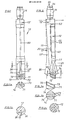
- the drilling tool 10 shown in FIGS. 1, 2 consists essentially of a drilling shaft 12 and a pressure piece 14.
- the drilling shaft 12 has a tip 11 and a drive connection 18, which can be designed, for example, as a thread.
- the outermost drive-side end of the drill shaft 12 is designed as an axial pressurizing surface 54, with which the drill shaft 12 is subjected to axial pressurization in the direction of arrow 35, e.g. B. is supported by a hammer drill on this or its receptacle.
- the cylindrical pilot hole 17 is shown in dash-dot lines. It can be seen that the drill shaft 12 has at its upper end a diameter 62 corresponding approximately to the diameter of the pilot hole 17. Otherwise, the detailed design of the drill shaft 12 can be seen from FIGS. 3 a to 3 d of EP-A1-0 242 638.
- the drill shaft 12 On the pressure piece 14 facing tip 11 of the drill shaft 12 has a side cutting edge 15 which protrudes radially beyond its outer circumference and is arranged such that in the coaxial position shown in FIG. 2 between the pilot hole 17 and the drill shaft 12 can produce undercut 36 shown in dash-dotted lines.
- the side cutting edge 15 is provided with a cutting edge 26 inclined to the drill shaft tip 11. Since the drilling tool 10 rotates clockwise, the drill shaft tip 11 is cut out in the area 38 in front of the side cutting edge 15 and is supported in the area 39 for driving it by the material of the drill shaft 12.
- the drill shaft 12 is provided with a flattened circumference 16 which extends from the drill shaft tip 11 to the drive connection 18. From Fig. 2 it can be seen that this flattening takes place evenly or at the same angle to the drill shaft axis 25. The angle is illustrated in FIG. 2 by reference number 60. The flattening results in side edges 40.
- the inclined surface 13 is inclined at approximately 40 ° to 70 °, preferably 65 °, to the drill shaft axis 25 in the axial direction of the arrow 35, that is to say inclined towards the pressure piece 14.
- the inclined surface 13 is approximately parallel to the diagonally opposite surface section of the sole. Axial loading of the drill shaft 12 results in a radial propulsion of the side cutting edge 15 via the inclined surface 13 to produce the undercut 36.
- the inclined surface 13 of the adjacent pressure piece surface is spatially adapted, which results from FIG. 1.
- the side cutting edge 15 is arranged without overlap with respect to the inclined surface 13, that is to say it is arranged horizontally higher than the uppermost region of the inclined surface 13, which results in particular from FIG. 2.
- This design of the drilling tool 10 serves in particular for stability in the area of the drill shaft tip 11, which is heavily stressed by the striking advance of the drilling tool 10.
- the attachment of the side cutting edge 15, for example a hard metal plate soldered into the drill shaft 12, is also less stressed by the above-described design of the drilling tool 10.
- a pressure piece 14 is fastened so that there is permanent cohesion in the axial direction.
- the drill shaft 12 can be axially inserted into and pulled out of the pilot hole 17 without any manipulations having to be carried out beforehand and / or afterwards with regard to the introduction of the pressure piece or its whereabouts in or in the pilot hole 17.
- the pressure piece 14 is intended for permanent use in connection with the drill shaft 12 due to its permanent attachment to the drill shaft tip 11 and must therefore be particularly resistant.
- it is preferably designed as a tempered forged part. An investment casting with corresponding properties can also be used.
- the assembly of the pressure piece 14 with the inclined surface 13 is such that both can move relative to one another in the radial direction.
- the pressure piece 14 has an undercut guide groove 71 which, according to the figures, is parallel to the inclined surface, that is to say has the same inclination towards the drill shaft axis as the inclined surface 13.
- This guide groove 71 engages Coupling projection 72 of the drill shaft tip 11, preferably axially positively.
- This coupling projection 72 is formed like a strip and at the same time undercut, so that the two coupling parts 71, 72 have to be pushed together for assembly in the plane of FIG. 2.
- the coupling piece 14 has a sliding surface 73.
- This sliding surface 73 extends in the radial direction of movement in which the relative displacements between the pressure piece 14 and the drill shaft tip 11 take place.
- the sliding surface 73 is curved transversely thereto and the figures show that the inclined surface 13 is curved accordingly.
- the coupling projection 72 has limited movement axially but also radially in the guide groove 71, accordingly the pressure piece 14 and the drill shaft tip 11 can move relative to one another. This movement play ensures that drilling dust arising on the sliding surface 73 during the drilling process does not lead to excessive stress on the coupling parts 71, 72 or to their jamming.
- the coupling parts 71, 72 are also relieved by the fact that the rotational driving forces occurring when the drill shaft 12 is driven in rotation are transmitted directly from the drill bit 11 via its inclined surface 13 to the curved sliding surface 73 of the pressure piece 14.
- the maximum outer diameter of the pressure piece 14 is somewhat smaller than the diameter of the pilot hole 17.
- the guide groove 71 is machined into the pressure piece 14, while the coupling projection 72 is fastened to the drill shaft tip 11 with a web 78 in such a way that its inclined surface 13 is divided into two equally large sections, each of which has an almost quarter-circular cross section. Accordingly, the coupling projection 72 is practically flush with the lowermost or outermost edges of the drill shaft tip 11. Accordingly, the sliding surface 73 of the coupling piece 14 is practically semicircular in cross section and provided with mutually parallel surface lines. In particular, from the comparison of FIG. 26 of EP-A1-0 242 638 and FIG. 2a it can be seen that the sliding surface 73 in the pressure piece 14 present here is considerably enlarged, which is due to the larger axial extent required to enclose the coupling projection 72 is conditional.
- the coupling projection 72 is inserted into the guide groove 71 until it bears against the transverse projections 75 thereof. The edges 76 are then deformed, thereby achieving the desired permanent assembly.
- the drill shaft 12 has a reduced outer radius in its circumferential region opposite the previously described flattening 16, which has an approximately semicircular cross section. This results from the recess shown in FIGS. 1, 2 of this peripheral drill shaft area between the diameter 62 at the upper, connection-side end 12 'of the drill shaft 12 and its projection 77 in the vicinity of the side cutting edge 15 because these two, i.e. the diameter 62 and the projection 77 have approximately a pre-bore radius.
- the projection 77 is dimensioned so that it comes to rest on the inner wall 17 ⁇ when the undercut 36 is completed by the side cutting edge 15.
- the projection 77 serves to maintain the exact central position of the drill shaft 12 after completion of the undercut 36, if the drill shaft has the above-described reduced outer radius or a free space to the inner wall 17 ⁇ of the pilot hole 17.
- the drill shaft 12 also has a bore 33 through which the drilling dust can be suctioned off.
- the bore 33 has two outlet channels 79, 80 which each slope from the pressure piece 14 to the connection-side end 12 'of the drill shaft 12 to facilitate the extraction of drilling dust.
- the opening channel 79 opens radially in the direction of rotation in front of the side cutting edge 15, see FIG. 1.
- the opening channel 80 is only present as required and is arranged diagonally opposite the side cutting edge 15 in such a way that it sucks off dust originating from a higher area of the side cutting edge 15.
- the drilling tool 10 is operated by first inserting the pressure piece 14 into the cylindrical pilot hole 17 and pressing it against the base of the pilot hole 17 by the drilling shaft 12.
- the inserted into the pilot hole 17 drill shaft lies with its flattened outer circumference 16 on the inner wall 17 ⁇ of the pilot hole 17 because the radially projecting side cutting edge 15 projects over the outer circumference of the drilling shaft 12 because of the depth of the undercut 36. If the inclined surface 13 of the drill shaft 12 is seated on the pressure piece 14, the drilling tool 10 can be axially loaded, whereby a radial force component is generated, namely in the direction of the projection of the side cutting edge 15.
- the cutting edge 26 digs with its cutting edge 26 in the the inner wall 17 ⁇ forming material and produces the ring groove-like undercut 36 shown in FIG. 2 when the drilling shaft 12 rotates.
- the drilling shaft 12 shifts axially inward into the pilot hole 17, its inclined surface 13 on the pressure piece 14 slipped.
- the drill shaft 12 performs circular wobbling movements when the machine is driven. He is supported in the beginning of the pilot hole 17 with the end 12 '. In this area, the drill shaft 12 can be tapered crowned.
Landscapes
- Engineering & Computer Science (AREA)
- Mechanical Engineering (AREA)
- General Engineering & Computer Science (AREA)
- Processing Of Stones Or Stones Resemblance Materials (AREA)
- Drilling Tools (AREA)
- Cutting Tools, Boring Holders, And Turrets (AREA)
- Drilling And Boring (AREA)
Applications Claiming Priority (2)
| Application Number | Priority Date | Filing Date | Title |
|---|---|---|---|
| DE3737746 | 1987-11-06 | ||
| DE19873737746 DE3737746A1 (de) | 1986-12-03 | 1987-11-06 | Bohrwerkzeug |
Publications (3)
| Publication Number | Publication Date |
|---|---|
| EP0315123A2 true EP0315123A2 (fr) | 1989-05-10 |
| EP0315123A3 EP0315123A3 (en) | 1990-07-04 |
| EP0315123B1 EP0315123B1 (fr) | 1992-08-12 |
Family
ID=6339964
Family Applications (1)
| Application Number | Title | Priority Date | Filing Date |
|---|---|---|---|
| EP88118178A Expired - Lifetime EP0315123B1 (fr) | 1987-11-06 | 1988-11-01 | Outil de perçage |
Country Status (4)
| Country | Link |
|---|---|
| EP (1) | EP0315123B1 (fr) |
| AT (1) | ATE79316T1 (fr) |
| DE (1) | DE3873691D1 (fr) |
| ES (1) | ES2034107T3 (fr) |
Cited By (1)
| Publication number | Priority date | Publication date | Assignee | Title |
|---|---|---|---|---|
| CN108788238A (zh) * | 2018-08-02 | 2018-11-13 | 中北大学 | 一种带有径向可倾瓦块的深孔加工智能钻杆系统 |
Family Cites Families (3)
| Publication number | Priority date | Publication date | Assignee | Title |
|---|---|---|---|---|
| DE8610234U1 (de) * | 1986-04-15 | 1987-08-20 | Eischeid, Karl, 5250 Engelskirchen | Bohrwerkzeug |
| ES2012067B3 (es) * | 1986-04-15 | 1990-03-01 | Karl Eischeid | Herramienta para taladrar |
| DE8632363U1 (de) * | 1986-12-03 | 1988-05-11 | Eischeid, Karl, 5250 Engelskirchen | Bohrwerkzeug |
-
1988
- 1988-11-01 DE DE8888118178T patent/DE3873691D1/de not_active Expired - Lifetime
- 1988-11-01 AT AT88118178T patent/ATE79316T1/de not_active IP Right Cessation
- 1988-11-01 ES ES198888118178T patent/ES2034107T3/es not_active Expired - Lifetime
- 1988-11-01 EP EP88118178A patent/EP0315123B1/fr not_active Expired - Lifetime
Cited By (2)
| Publication number | Priority date | Publication date | Assignee | Title |
|---|---|---|---|---|
| CN108788238A (zh) * | 2018-08-02 | 2018-11-13 | 中北大学 | 一种带有径向可倾瓦块的深孔加工智能钻杆系统 |
| CN108788238B (zh) * | 2018-08-02 | 2023-09-15 | 中北大学 | 一种带有径向可倾瓦块的深孔加工智能钻杆系统 |
Also Published As
| Publication number | Publication date |
|---|---|
| DE3873691D1 (de) | 1992-09-17 |
| ATE79316T1 (de) | 1992-08-15 |
| EP0315123B1 (fr) | 1992-08-12 |
| EP0315123A3 (en) | 1990-07-04 |
| ES2034107T3 (es) | 1993-04-01 |
Similar Documents
| Publication | Publication Date | Title |
|---|---|---|
| DE2945766C2 (de) | Bohrkrone und Bohrwerkzeug mit einer solchen Bohrkrone | |
| DE102010025653B4 (de) | Rotations-Schneidwerkzeug | |
| DE2709830C3 (de) | Zentrumsbohrer zur Bearbeitung von Holz, Kunststoff u.dgl. | |
| WO1990000957A1 (fr) | Dispositif de transmission de couple sur les machines-outils | |
| EP0043000A1 (fr) | Outil de forage à organes coupants expansibles | |
| DE19526686B4 (de) | Mehrstufenbohrer | |
| DE3507817A1 (de) | Bohrer zur erzeugung einer hinterschneidung in einer bohrung | |
| EP0551795B1 (fr) | Outil pour forage à percussion et ciselage et mandrin pour cet outil | |
| EP0242638B1 (fr) | Outillage pour foret | |
| DE2331467B2 (de) | Vorrichtung zum Ausbohren einer Bohrung mit einem zylindrischen und einem konischen Bereich | |
| DE9104326U1 (de) | Bohrvorrichtung zum Herstellen von Bohrungen mit Hinterschneidungen | |
| DE102007038254A1 (de) | Bauteil mit Verbindungseinrichtung und Herstellungsverfahren | |
| DE10359854A1 (de) | Zylinderkopfbohrer mit Hartmetallschneiden und Kunststoffschaft | |
| EP3656494A1 (fr) | Foret étagé | |
| DE3118691C2 (fr) | ||
| DE3025890A1 (de) | Bohrer fuer bohrhaemmer, insbes. zum bohren in gestein, beton o.dgl. | |
| DE4441820B4 (de) | Bohr- und/oder Schlaghammer | |
| EP0315123B1 (fr) | Outil de perçage | |
| DE3528173A1 (de) | Werkzeug und verfahren zum bohren eines hinterstochenen loches | |
| EP0791423B1 (fr) | Dispositif porte-foret avec un foret | |
| EP0170877A1 (fr) | Rotor pour métier à filer à fibres libérées et son procédé de fabrication | |
| DE3620389C2 (fr) | ||
| DE3530296A1 (de) | Vorrichtung zum herstellen von wandausnehmungen | |
| DD236487A5 (de) | Werkzeug und verfahren zum bohren eines hinterstochenen loches | |
| DE10213024B4 (de) | Handwerkzeug und Messer zum Entgraten |
Legal Events
| Date | Code | Title | Description |
|---|---|---|---|
| PUAI | Public reference made under article 153(3) epc to a published international application that has entered the european phase |
Free format text: ORIGINAL CODE: 0009012 |
|
| AK | Designated contracting states |
Kind code of ref document: A2 Designated state(s): AT BE CH DE ES FR GB GR IT LI LU NL SE |
|
| PUAL | Search report despatched |
Free format text: ORIGINAL CODE: 0009013 |
|
| AK | Designated contracting states |
Kind code of ref document: A3 Designated state(s): AT BE CH DE ES FR GB GR IT LI LU NL SE |
|
| 17P | Request for examination filed |
Effective date: 19901010 |
|
| 17Q | First examination report despatched |
Effective date: 19910708 |
|
| GRAA | (expected) grant |
Free format text: ORIGINAL CODE: 0009210 |
|
| AK | Designated contracting states |
Kind code of ref document: B1 Designated state(s): AT BE CH DE ES FR GB GR IT LI LU NL SE |
|
| PG25 | Lapsed in a contracting state [announced via postgrant information from national office to epo] |
Ref country code: SE Free format text: THE PATENT HAS BEEN ANNULLED BY A DECISION OF A NATIONAL AUTHORITY Effective date: 19920812 Ref country code: GR Free format text: LAPSE BECAUSE OF FAILURE TO SUBMIT A TRANSLATION OF THE DESCRIPTION OR TO PAY THE FEE WITHIN THE PRESCRIBED TIME-LIMIT Effective date: 19920812 |
|
| REF | Corresponds to: |
Ref document number: 79316 Country of ref document: AT Date of ref document: 19920815 Kind code of ref document: T |
|
| GBT | Gb: translation of ep patent filed (gb section 77(6)(a)/1977) | ||
| REF | Corresponds to: |
Ref document number: 3873691 Country of ref document: DE Date of ref document: 19920917 |
|
| ITF | It: translation for a ep patent filed | ||
| ET | Fr: translation filed | ||
| PG25 | Lapsed in a contracting state [announced via postgrant information from national office to epo] |
Ref country code: LU Free format text: LAPSE BECAUSE OF NON-PAYMENT OF DUE FEES Effective date: 19921130 |
|
| REG | Reference to a national code |
Ref country code: ES Ref legal event code: FG2A Ref document number: 2034107 Country of ref document: ES Kind code of ref document: T3 |
|
| PLBE | No opposition filed within time limit |
Free format text: ORIGINAL CODE: 0009261 |
|
| STAA | Information on the status of an ep patent application or granted ep patent |
Free format text: STATUS: NO OPPOSITION FILED WITHIN TIME LIMIT |
|
| 26N | No opposition filed | ||
| PGFP | Annual fee paid to national office [announced via postgrant information from national office to epo] |
Ref country code: GB Payment date: 19961023 Year of fee payment: 9 Ref country code: BE Payment date: 19961023 Year of fee payment: 9 |
|
| PGFP | Annual fee paid to national office [announced via postgrant information from national office to epo] |
Ref country code: CH Payment date: 19961029 Year of fee payment: 9 |
|
| PGFP | Annual fee paid to national office [announced via postgrant information from national office to epo] |
Ref country code: ES Payment date: 19961112 Year of fee payment: 9 |
|
| PGFP | Annual fee paid to national office [announced via postgrant information from national office to epo] |
Ref country code: AT Payment date: 19961114 Year of fee payment: 9 |
|
| PGFP | Annual fee paid to national office [announced via postgrant information from national office to epo] |
Ref country code: FR Payment date: 19961127 Year of fee payment: 9 |
|
| PGFP | Annual fee paid to national office [announced via postgrant information from national office to epo] |
Ref country code: NL Payment date: 19961130 Year of fee payment: 9 |
|
| PG25 | Lapsed in a contracting state [announced via postgrant information from national office to epo] |
Ref country code: GB Free format text: LAPSE BECAUSE OF NON-PAYMENT OF DUE FEES Effective date: 19971101 Ref country code: AT Free format text: LAPSE BECAUSE OF NON-PAYMENT OF DUE FEES Effective date: 19971101 |
|
| PG25 | Lapsed in a contracting state [announced via postgrant information from national office to epo] |
Ref country code: ES Free format text: LAPSE BECAUSE OF NON-PAYMENT OF DUE FEES Effective date: 19971102 |
|
| PG25 | Lapsed in a contracting state [announced via postgrant information from national office to epo] |
Ref country code: LI Free format text: LAPSE BECAUSE OF NON-PAYMENT OF DUE FEES Effective date: 19971130 Ref country code: FR Free format text: THE PATENT HAS BEEN ANNULLED BY A DECISION OF A NATIONAL AUTHORITY Effective date: 19971130 Ref country code: CH Free format text: LAPSE BECAUSE OF NON-PAYMENT OF DUE FEES Effective date: 19971130 Ref country code: BE Free format text: LAPSE BECAUSE OF NON-PAYMENT OF DUE FEES Effective date: 19971130 |
|
| BERE | Be: lapsed |
Owner name: EISCHEID KARL Effective date: 19971130 |
|
| PG25 | Lapsed in a contracting state [announced via postgrant information from national office to epo] |
Ref country code: NL Free format text: LAPSE BECAUSE OF NON-PAYMENT OF DUE FEES Effective date: 19980601 |
|
| GBPC | Gb: european patent ceased through non-payment of renewal fee |
Effective date: 19971101 |
|
| REG | Reference to a national code |
Ref country code: CH Ref legal event code: PL |
|
| NLV4 | Nl: lapsed or anulled due to non-payment of the annual fee |
Effective date: 19980601 |
|
| REG | Reference to a national code |
Ref country code: FR Ref legal event code: ST |
|
| PGFP | Annual fee paid to national office [announced via postgrant information from national office to epo] |
Ref country code: DE Payment date: 19991119 Year of fee payment: 12 |
|
| PG25 | Lapsed in a contracting state [announced via postgrant information from national office to epo] |
Ref country code: DE Free format text: LAPSE BECAUSE OF NON-PAYMENT OF DUE FEES Effective date: 20010801 |
|
| REG | Reference to a national code |
Ref country code: ES Ref legal event code: FD2A Effective date: 19981212 |
|
| PG25 | Lapsed in a contracting state [announced via postgrant information from national office to epo] |
Ref country code: IT Free format text: LAPSE BECAUSE OF NON-PAYMENT OF DUE FEES;WARNING: LAPSES OF ITALIAN PATENTS WITH EFFECTIVE DATE BEFORE 2007 MAY HAVE OCCURRED AT ANY TIME BEFORE 2007. THE CORRECT EFFECTIVE DATE MAY BE DIFFERENT FROM THE ONE RECORDED. Effective date: 20051101 |